|
|

Table Of Contents
Create Circuits and VT Tunnels
NTP-50 Verify System Acceptance
NTP-51 Create an Automatically Routed DS-1 Circuit
NTP-52 Create a Manually Routed DS-1 Circuit
NTP-53 Create a Unidirectional DS-1 Circuit with Multiple Drops
NTP-54 Create an Automatically Routed DS-3 Circuit
NTP-55 Create a Manually Routed DS-3 Circuit
NTP-56 Create a Unidirectional DS-3 Circuit with Multiple Drops
DLP-95 Provision a DS-1 or DS-3 Circuit Source and Destination
DLP-96 Provision a DS-1 or DS-3 Circuit Route
NTP-58 Test Electrical Circuits
NTP-59 Create an Automatically Routed Optical Circuit
NTP-60 Create a Manually Routed Optical Circuit
NTP-61 Create a Unidirectional Optical Circuit with Multiple Drops
DLP-97 Provision an Optical Circuit Source and Destination
DLP-98 Provision an Optical Circuit Route
NTP-63 Create E Series Ethernet Circuits
DLP-99 Determine Available VLANs
DLP-100 Provision an E Series EtherSwitch Circuit (Multicard or Single-Card)
DLP-101 Create an E Series Shared Packet Ring Ethernet Circuit
DLP-102 Create an E Series Hub and Spoke Ethernet Circuit
DLP-103 Provision an E Series Single-Card EtherSwitch Manual Cross-Connect
DLP-104 Provision an E Series Multicard EtherSwitch Manual Cross-Connect
DLP-105 Provision E Series Ethernet Ports
DLP-106 Provision E Series Ethernet Ports for VLAN Membership
NTP-64 Test E Series Ethernet Circuits
NTP-65 Create G Series Ethernet Circuits
DLP-107 Create a G1000-4 EtherSwitch Circuit
DLP-108 Provision a G1000-4 Manual Cross-Connect
DLP-109 Provision G1000-4 Ethernet Ports
NTP-66 Test G Series Ethernet Circuits
Create Circuits and VT Tunnels
This chapter explains how to create Cisco ONS 15454 electrical circuits and VT tunnels, optical circuits, and Ethernet circuits.
For additional information about ONS 15454 circuits, refer to the Circuits chapter and Circuit Routing appendix in the Cisco ONS 15454 Reference Guide.
Before You Begin
Before performing any of the following procedures, investigate all alarms and clear any trouble conditions. Refer to the Cisco ONS 15454 Troubleshooting Guide as necessary.
This section lists the chapter procedures (NTPs). Turn to a procedure for applicable tasks (DLPs).
1.
NTP-50 Verify System Acceptance—Complete this procedure before you create any circuits.
2.
3.
4.
5.
6.
7.
8.
9.
10.
11.
12.
13.
14.
15.
16.
17.
Table 6-1 defines ONS 15454 circuit creation terms and options.
ONS 15454 circuits are either a VT or a STS circuit. Table 6-2 shows the circuit source and destination options that display for VT circuits. Table 6-3 shows the options that display for STS circuits.
NTP-50 Verify System Acceptance
Purpose
This procedure verifies that the ONS 15454 network is ready for circuit provisioning.
Tools/Equipment
None
Prerequisite Procedures
Required/As Needed
Required
Onsite/Remote
Onsite or remote
Step 1
Step 2
Note
Step 3
If all network nodes do not display after a few minutes, or if a node icon is grey with an IP address under it, do not continue. Go to Chapter 5, "Turn Up Network," to review the network turn-up procedure appropriate for your network topology, or refer to the Cisco ONS 15454 Troubleshooting Guide for troubleshooting procedures.
Step 4
Step 5
Step 6
a.
b.
c.
d.
e.
–
–
–
–
–
If corrections need to be made, go to "NTP-40 Provision the BLSR Nodes" procedure on page 5-13 for instructions.
f.
g.
h.
i.
j.
Step 7
Step 8
NTP-51 Create an Automatically Routed DS-1 Circuit
Purpose
This procedure creates an automatically routed DS-1 circuit, meaning CTC chooses the circuit route based on the parameters you set at circuit creation and on the system load.
Tools/Equipment
None
Prerequisite Procedures
NTP-50 Verify System Acceptance
Required/As Needed
As needed
Onsite/Remote
Onsite or remote
Step 1
Step 2
Step 3
•
•
•
•
•
•
•
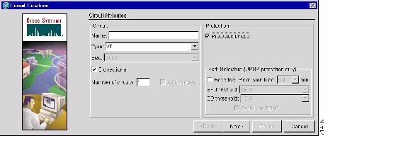
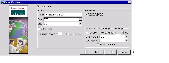
Figure 6-1 Setting circuit attributes for a DS-1 circuit
Step 4
•
•
•
•
•
Step 5
Step 6
Step 7
•
•
Select either, both, or none, based on your preferences.
Note
Step 8
•
•
•
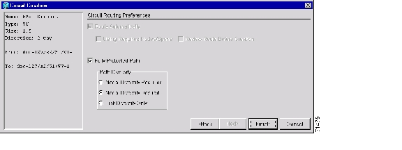
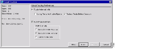
Figure 6-2 Setting circuit routing preferences for a DS-1 circuit
Step 9
a.
b.
c.
d.
e.
Step 10
a.
b.
c.
Step 11
•
•
•
Step 12
Step 13
NTP-52 Create a Manually Routed DS-1 Circuit
Step 1
Step 2
Step 3
•
•
•
•
•
•
•
Step 4
•
•
•
•
•
Step 5
Step 6
Step 7
Note
Step 8
•
•
•
Step 9
Step 10
When provisioning a protected circuit, you only need to select one of the BLSR or 1+1 span paths from the source to the drop. If you select unprotected spans as part of the path, you must provision both the working and protect paths.
Step 11
Step 12
Step 13
NTP-53 Create a Unidirectional DS-1 Circuit with Multiple Drops
Purpose
This procedure creates a unidirectional DS-1 circuit with multiple drops.
Tools/Equipment
None
Prerequisite Procedures
NTP-50 Verify System Acceptance
Required/As Needed
As needed
Onsite/Remote
Onsite or remote
Step 1
Step 2
Step 3
•
•
•
•
•
•
•
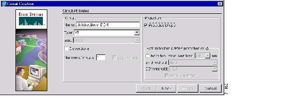
Figure 6-3 Setting circuit attributes for a DS-1 circuit
Step 4
•
•
•
•
•
Step 5
Step 6
Step 7
Note
Step 8
•
•
•
Step 9
Step 10
When provisioning a protected circuit, you only need to select one path of BLSR or 1+1 spans from the source to the drop. If you select unprotected spans as part of the path, you must provision both the working and protect paths.
Step 11
•
•
•
Step 12
Step 13
All nodes in the DCC network are displayed on the network. Circuit source and destination information appears under the source and destination nodes. To display a detailed view of the circuit, click Show Detailed Map. You can also rearrange a node icon by selecting the node with the left mouse button while simultaneously pressing Ctrl, then dragging the icon to the new location.
Step 14
Step 15
Step 16
a.
b.
c.
d.
Note
Step 17
Step 18
Step 19
Step 20
NTP-54 Create an Automatically Routed DS-3 Circuit
Purpose
Creates an automatically routed DS-3 circuit. CTC routes the circuit automatically based on circuit creation parameters and the system load.
Tools/Equipment
None
Prerequisite Procedures
NTP-50 Verify System Acceptance
Required/As Needed
As needed
Onsite/Remote
Onsite or remote
Step 1
Step 2
Step 3
•
•
•
•
•
•
•
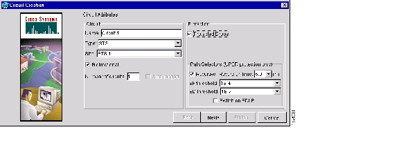
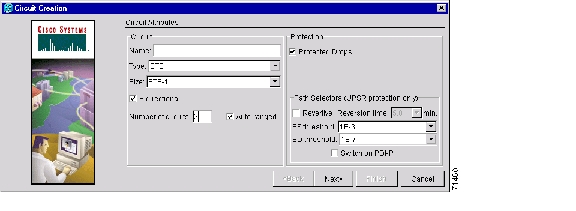
Figure 6-4 Setting circuit attributes for a DS-3 circuit
Step 4
•
•
•
•
•
•
Step 5
Step 6
•
•
Note
Step 7
•
•
•
Figure 6-5 Setting circuit routing preferences for a DS-3 circuit
Step 8
a.
b.
c.
d.
e.
Note
Step 9
a.
b.
c.
Step 10
•
•
•
Step 11
Step 12
NTP-55 Create a Manually Routed DS-3 Circuit
Purpose
This procedure creates a DS-3 circuit and allows you to choose the circuit route.
Tools/Equipment
None
Prerequisite Procedures
NTP-50 Verify System Acceptance
Required/As Needed
As needed
Onsite/Remote
Onsite or remote
Step 1
Step 2
Step 3
•
•
•
•
•
•
•
Step 4
•
•
•
•
•
Step 5
Step 6
Step 7
Note
Step 8
•
•
•
Step 9
Step 10
When provisioning a protected circuit, you only need to select one of the BLSR or 1+1 span paths from the source to the drop. If you are in a UPSR and PPMN, you must provision both the working and protect paths.
Step 11
Step 12
Step 13
NTP-56 Create a Unidirectional DS-3 Circuit with Multiple Drops
Purpose
This procedure creates a unidirectional DS-3 circuit with multiple drops.
Tools/Equipment
None
Prerequisite Procedures
NTP-50 Verify System Acceptance
Required/As Needed
As needed
Onsite/Remote
Onsite or remote
Step 1
Step 2
Step 3
•
•
•
•
•
•
•
Figure 6-6 Setting circuit attributes for a unidirectional DS-3 circuit
Step 4
•
•
•
•
•
Step 5
Step 6
Step 7
Note
Step 8
•
•
•
Step 9
Step 10
When provisioning a protected circuit, you only need to select one path of BLSR or 1+1 span paths from the source to the drop. If you select unprotected spans as part of the path, you must select both the working and protect paths.
Step 11
•
•
•
Step 12
Step 13
Step 14
Step 15
Step 16
a.
b.
c.
d.
Note
Step 17
Step 18
Step 19
Step 20
DLP-95 Provision a DS-1 or DS-3 Circuit Source and Destination
Note
Step 1
Step 2
Step 3
Step 4
Step 5
Step 6
Step 7
Step 8
Step 9
Step 10
Step 11
Step 12
DLP-96 Provision a DS-1 or DS-3 Circuit Route
Step 1
Step 2
Note
Step 3
Step 4
Step 5
When provisioning a protected circuit, you only need to select one of the BLSR or 1+1 span paths from the source to the drop. If you select unprotected spans as part of the path, you must provision both the working and protect paths.
Step 6
NTP-57 Create a VT Tunnel
Purpose
This procedure creates a VT tunnel from source to destination nodes.
Tools/Equipment
None
Prerequisite Procedures
Required/As Needed
As needed
Onsite/Remote
Onsite or remote
Step 1
Step 2
Step 3
•
•
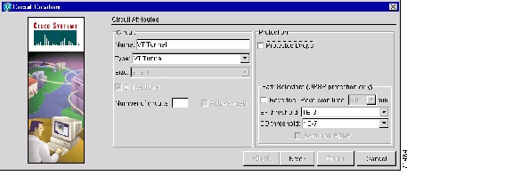
Figure 6-7 Setting attributes for a VT tunnel
Step 4
Step 5
Step 6
Step 7
Step 8
Step 9
•
•
Note
Step 10
a.
b.
c.
d.
e.
Step 11
a.
b.
c.
Step 12
Step 13
Step 14
NTP-58 Test Electrical Circuits
Note
Purpose
Use this procedure to test a DS-1 and DS-3 circuit.
Tools/Equipment
A test set and all appropriate cables
Prerequisite Procedures
One of the following:
NTP-51 Create an Automatically Routed DS-1 Circuit
NTP-52 Create a Manually Routed DS-1 Circuit
NTP-53 Create a Unidirectional DS-1 Circuit with Multiple Drops
NTP-54 Create an Automatically Routed DS-3 Circuit
NTP-55 Create a Manually Routed DS-3 Circuit
NTP-56 Create a Unidirectional DS-3 Circuit with Multiple DropsRequired/As Needed
Required
Onsite/Remote
Onsite
Step 1
Step 2
Step 3
Step 4
a.
b.
c.
Step 5
Step 6
Step 7
Step 8
a.
b.
Step 9
a.
b.
Step 10
•
•
•
•
Step 11
Step 12
Step 13
Step 14
•
•
Step 15
Step 16
Step 17
NTP-59 Create an Automatically Routed Optical Circuit
Step 1
Step 2
Step 3
•
•
•
•
•
•
•
Figure 6-8 Setting circuit attributes for an optical circuit
Step 4
•
•
•
•
•
Step 5
Step 6
Step 7
•
•
Step 8
•
•
•
Figure 6-9 Setting circuit routing preferences for an optical circuit
.
Step 9
a.
b.
c.
d.
e.
Step 10
a.
b.
c.
Step 11
•
•
•
Step 12
Step 13
NTP-60 Create a Manually Routed Optical Circuit
Step 1
Step 2
Step 3
•
•
•
•
•
•
•
Step 4
•
•
•
•
•
Step 5
Step 6
Step 7
Note
Step 8
•
•
•
Step 9
Step 10
When provisioning a protected circuit, you only need to select one path of BLSR or 1+1 spans from the source to the drop. If you select unprotected spans as part of the path, select two different paths for the unprotected segment of the path.
Step 11
Step 12
Step 13
NTP-61 Create a Unidirectional Optical Circuit with Multiple Drops
Step 1
Step 2
Step 3
•
•
•
•
•
•
•
Step 4
•
•
•
•
•
•
Step 5
Step 6
Note
Step 7
•
•
•
Note
Step 8
Step 9
Note
Step 10
•
•
•
Step 11
Step 12
Step 13
Step 14
Step 15
a.
b.
c.
d.
Step 16
Step 17
Step 18
Step 19
DLP-97 Provision an Optical Circuit Source and Destination
Purpose
This task provisions the source and destination cards for an optical circuit.
Tools/Equipment
None
Prerequisite Procedures
Required/As Needed
As needed
Onsite/Remote
Onsite or remote
Step 1
Step 2
Step 3
Note
Step 4
Step 5
Step 6
Step 7
Step 8
Step 9
Step 10
Step 11
DLP-98 Provision an Optical Circuit Route
Purpose
This task provisions an optical circuit route for manually-routed circuits.
Tools/Equipment
None
Prerequisite Procedures
Required/As Needed
As needed
Onsite/Remote
Onsite or remote
Step 1
Step 2
Step 3
Step 4
Step 5
NTP-62 Test Optical Circuits
Note
Purpose
Use this procedure to test an optical circuit.
Tools/Equipment
Test set capable of optical speeds, appropriate fibers and attenuators
Prerequisite Procedures
NTP-59 Create an Automatically Routed Optical Circuit
Required/As Needed
Required
Onsite/Remote
Onsite
Step 1
Step 2
Step 3
Step 4
Step 5
Step 6
Step 7
Step 8
Step 9
Step 10
a.
b.
Step 11
a.
b.
Step 12
•
•
•
•
Step 13
Step 14
Step 15
Step 16
•
•
Step 17
Step 18
Step 19
NTP-63 Create E Series Ethernet Circuits
Purpose
This procedure creates an EtherSwitch, shared packet ring, or hub and spoke Ethernet circuit.
Tools/Equipment
None
Prerequisite Procedures
Required/As Needed
As needed
Onsite/Remote
Onsite
Step 1
Step 2
Step 3
Step 4
Step 5
Step 6
Note
Step 7
•
•
Step 8
DLP-99 Determine Available VLANs
Purpose
This task verifies that the network has the capacity to support the additional new VLANs required for the creation E-Series circuits.
Tools/Equipment
E Series Ethernet cards (E100T-12/E100T-G, E1000-2/E1000-2-G) must be installed at each end of the Ethernet circuit.
Prerequisite Procedures
NTP-50 Verify System Acceptance
Required/As Needed
As needed
Onsite/Remote
Onsite or remote
Step 1
Step 2
Step 3
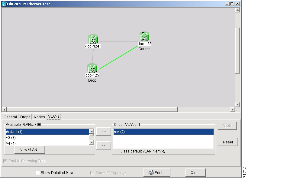
The Edit Circuit dialog displays the number of VLANs used by circuits and the total number of VLANs available for use.
Step 4
Caution
Figure 6-10 Edit Circuit dialog with VLANs tab selected
Step 5
DLP-100 Provision an E Series EtherSwitch Circuit (Multicard or Single-Card)
Purpose
This task creates a multicard or single-card EtherSwitch Circuit
Tools/Equipment
E Series Ethernet cards (E100T-12/E100T-G, E1000-2/E1000-2-G) must be installed at each end of the Ethernet circuit.
Prerequisite Procedures
NTP-50 Verify System Acceptance
Required/As Needed
As needed
Onsite/Remote
Onsite or remote
Step 1
Step 2
Step 3
•
•
Step 4
Step 5
Step 6
Step 7
Step 8
•
•
•
•
•
•
•
Step 9
•
•
•
•
•
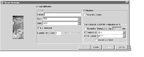
Figure 6-11 Provisioning an Ethernet circuit
Step 10
Step 11
a.
b.
–
–
Step 12
Step 13
a.
b.
–
–
Step 14
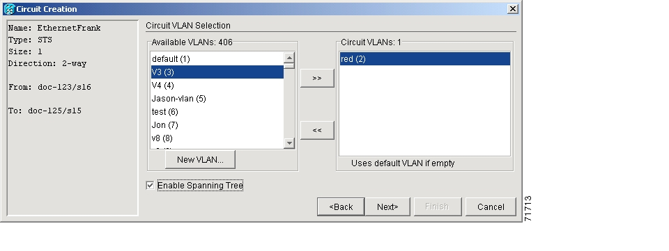
Figure 6-12 Circuit VLAN selection dialog with Enable Spanning Tree checkbox
Step 15
Step 16
•
•
Step 17
Step 18
Step 19
Caution
Caution
Caution
Note
Note
Step 20
Step 21
•
•
•
•
Step 22
Step 23
Step 24
DLP-101 Create an E Series Shared Packet Ring Ethernet Circuit
Purpose
This task creates a shared packet ring Ethernet circuit.
Tools/Equipment
E Series Ethernet cards (E100T-12/E100T-G, E1000-2/E1000-2-G) must be installed at both Ethernet circuit endpoint nodes.
Prerequisite Procedures
NTP-50 Verify System Acceptance
Required/As Needed
As needed
Onsite/Remote
Onsite or remote
Step 1
Step 2
Step 3
Step 4
Step 5
Step 6
Step 7
•
•
•
•
•
•
•
Step 8
•
•
•
•
•
Step 9
Step 10
a.
b.
Step 11
Step 12
a.
b.
Step 13
Step 14
a.
b.
•
•
c.
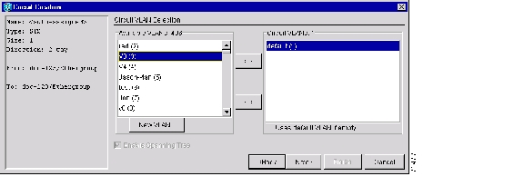
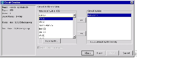
Figure 6-13 Selecting a VLAN
Step 15
Note
Step 16
Step 17
Step 18
The span turns white.
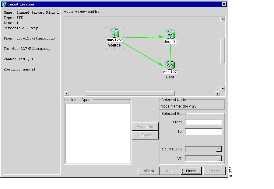
Figure 6-14 Adding a span
Step 19
The span turns blue and adds the span to the Included Spans field.
Step 20
Step 21
The span turns white.
Step 22
The span turns blue.
Step 23
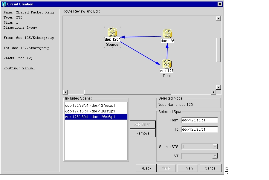
Figure 6-15 Viewing a span
Step 24
Note
Step 25
Step 26
Step 27
DLP-102 Create an E Series Hub and Spoke Ethernet Circuit
Purpose
This task creates a hub and spoke Ethernet circuit
Tools/Equipment
E Series Ethernet cards (E100T-12/E100T-G, E1000-2/E1000-2-G) must be installed at both Ethernet circuit end point nodes.
Prerequisite Procedures
NTP-50 Verify System Acceptance
Required/As Needed
As needed
Onsite/Remote
Onsite or remote
Step 1
Step 2
Step 3
Step 4
Step 5
Step 6
Step 7
•
•
•
•
•
•
•
Step 8
•
•
•
•
•
Step 9
Step 10
a.
b.
Step 11
Step 12
a.
b.
Step 13
Step 14
a.
b.
•
•
c.
Figure 6-16 Selecting a VLAN
Step 15
Note
Step 16
Step 17
•
•
•
•
•
If the circuit information is not correct, click the Back button and repeat the procedure with the correct information.
Note
Step 18
Step 19
Step 20
Step 21
Step 22
Step 23
Step 24
Step 25
Step 26
•
•
•
•
•
•
•
Step 27
•
•
•
•
•
Step 28
Step 29
a.
b.
Step 30
Step 31
a.
b.
Step 32
Step 33
Step 34
Step 35
•
•
•
•
•
If the circuit information is not correct, click the Back button and repeat the procedure with the correct information. You can also click Finish, delete the completed circuit, and start the procedure from the beginning.
Step 36
Step 37
Step 38
DLP-103 Provision an E Series Single-Card EtherSwitch Manual Cross-Connect
Purpose
This task manually creates a Multicard EtherSwitch cross-connect between E Series Ethernet cards and an OC-N cards connected to non-ONS equipment.
Tools/Equipment
E Series Ethernet cards (E100T-12/E100T-G, E1000-2/E1000-2-G) must be installed at the circuit source node.
Prerequisite Procedures
NTP-50 Verify System Acceptance
Required/As Needed
As needed
Onsite/Remote
Onsite or remote
Step 1
Note
Step 2
Step 3
Step 4
Step 5
•
•
•
•
•
•
•
Step 6
•
•
•
•
•
Step 7
Step 8
a.
b.
Step 9
Step 10
a.
b.
c.
Step 11
Step 12
a.
b.
•
•
c.
Figure 6-17 Selecting a VLAN
Step 13
Step 14
Step 15
•
•
•
•
•
If the information is not correct, click the Back button and repeat the procedure with the correct information.
Step 16
Step 17
Step 18
DLP-104 Provision an E Series Multicard EtherSwitch Manual Cross-Connect
Purpose
This task manually creates a Multicard EtherSwitch cross-connect between E Series Ethernet cards and an OC-N cards connected to non-ONS equipment.
Tools/Equipment
E Series Ethernet cards (E100T-12/E100T-G, E1000-2/E1000-2-G) must be installed at the circuit source node.
Prerequisite Procedures
NTP-50 Verify System Acceptance
Required/As Needed
As needed
Onsite/Remote
Onsite or remote
Step 1
Note
Step 2
Step 3
Step 4
Step 5
Step 6
Step 7
•
•
•
•
•
•
•
Step 8
•
•
•
•
•
Step 9
Step 10
a.
b.
Step 11
Step 12
The Slot field automatically is provisioned for Ethergroup.
Step 13
Step 14
a.
b.
•
•
c.
Figure 6-18 Selecting a VLAN
Step 15
Step 16
The Circuit Creation (Circuit Routing Preferences) dialog box opens.
Step 17
•
•
•
•
•
If the information is not correct, click the Back button and repeat the procedure with the correct information.
Step 18
Step 19
Step 20
Step 21
Step 22
Step 23
The Edit Circuit dialog box opens.
Step 24
The Define New Drop dialog box opens.
Step 25
Step 26
Step 27
Step 28
Step 29
Step 30
Note
Caution
Step 31
DLP-105 Provision E Series Ethernet Ports
Purpose
This task enables ports for the E100T-12, E100T-G, E1000-2, and E1000-2-G cards.
Tools/Equipment
None
Prerequisite Procedures
NTP-50 Verify System Acceptance
Required/As Needed
Required to enable Ethernet traffic
Onsite/Remote
Onsite or remote
Step 1
Step 2
Step 3
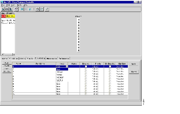
Figure 6-19 Provisioning E-100 Series Ethernet ports
Step 4
•
•
–
–
Note
•
•
•
Step 5
Step 6
Step 7
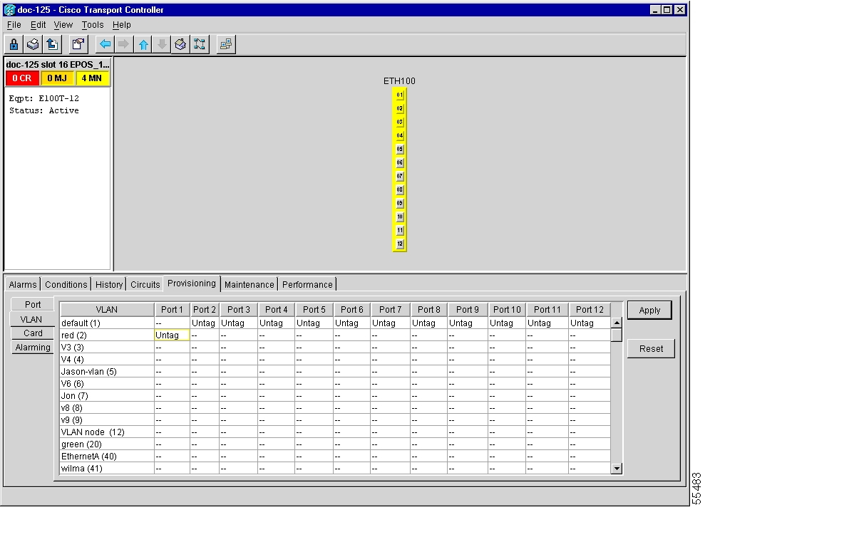
DLP-106 Provision E Series Ethernet Ports for VLAN Membership
Purpose
This task provisions E series Ethernet card ports for VLAN membership
Tools/Equipment
None
Prerequisite Procedures
NTP-50 Verify System Acceptance
Required/As Needed
Required to enable Ethernet traffic on E series Ethernet cards
Onsite/Remote
Onsite or remote
Step 1
Step 2
Step 3
Figure 6-20 Configuring VLAN membership for individual Ethernet ports
Step 4
a.
b.
Note
c.
Note
Step 5
.
Note
Note
Step 6
NTP-64 Test E Series Ethernet Circuits
Note
Step 1
Step 2
Step 3
Step 4
•
•
•
•
Step 5
Step 6
Step 7
Step 8
Note
Step 9
Step 10
Step 11
•
•
Configure your test set according to local site practice. For information about configuring your test set, see your test set user guide.
Step 12
Step 13
NTP-65 Create G Series Ethernet Circuits
Purpose
Use this procedure to create circuits with a source or destination G1000-4 card.
Tools/Equipment
A G1000-4 Ethernet card must be installed at each end of the Ethernet circuit.
Prerequisite Procedures
NTP-50 Verify System Acceptance
Required/As Needed
As needed
Onsite/Remote
Onsite or remote
Step 1
Step 2
Step 3
•
•
Step 4
Step 5
DLP-107 Create a G1000-4 EtherSwitch Circuit
Purpose
This task creates an EtherSwitch circuit on the G1000-4 card.
Tools/Equipment
A G1000-4 Ethernet card must be installed at each end of the Ethernet circuit.
Prerequisite Procedures
NTP-50 Verify System Acceptance
Required/As Needed
As needed
Onsite/Remote
Onsite or remote
Step 1
•
•
•
•
•
•
•
Step 2
•
•
•
•
•
Figure 6-21 Provisioning a G1000-4 Ethernet circuit
Step 3
Step 4
a.
b.
c.
Step 5
Step 6
a.
b.
c.
Step 7
Step 8
•
•
•
•
Step 9
Note
Step 10
DLP-108 Provision a G1000-4 Manual Cross-Connect
Purpose
This task manually creates a manual cross-connect between a G1000-4 Ethernet card and an OC-N cards connected to non-ONS equipment.
Tools/Equipment
A G1000-4 card must be installed at the circuit source node.
Prerequisite Procedures
NTP-50 Verify System Acceptance
Required/As Needed
As needed
Onsite/Remote
Onsite or remote
Note
Step 1
•
•
•
•
•
•
•
Step 2
•
•
•
•
•
Figure 6-22 Provisioning an Ethernet circuit
Step 3
Step 4
a.
b.
c.
Step 5
Step 6
a.
b.
c.
Step 7
Step 8
•
•
•
•
If the information is not correct, click the Back button and repeat the procedure with the correct information.
Step 9
Step 10
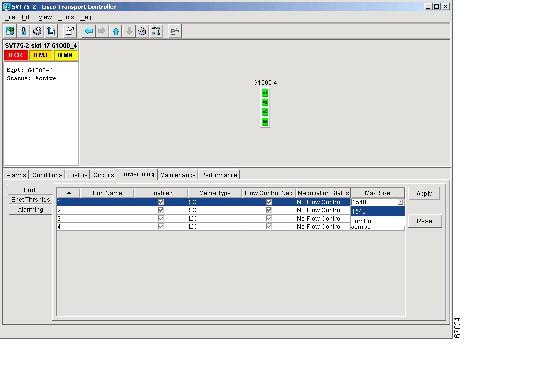
DLP-109 Provision G1000-4 Ethernet Ports
Purpose
This task provisions the G1000-4 ports for Ethernet circuits
Tools/Equipment
None
Prerequisite Procedures
NTP-50 Verify System Acceptance
Required/As Needed
Required to enable Ethernet traffic on the G1000-4
Onsite/Remote
Onsite or remote
Step 1
Step 2
Step 3
Figure 6-23 Provisioning G1000-4 Ethernet ports
Step 4
•
•
•
Note
•
Note
Step 5
Step 6
a.
b.
Note
Step 7
NTP-66 Test G Series Ethernet Circuits
Note
Step 1
Step 2
Step 3
Step 4
•
•
•
•
Step 5
Step 6
Note
Step 7
Step 8
Step 9
•
•
Configure your test set according to local site practice. For information about configuring your test set, see your test set user guide.
Step 10
Step 11
![]()
![]()
![]()
![]()
![]()
![]()
![]()
![]()
Posted: Fri Feb 22 13:47:55 PST 2008
All contents are Copyright © 1992--2008 Cisco Systems, Inc. All rights reserved.
Important Notices and Privacy Statement.