|
|

Table Of Contents
Using the Service Configuration Editor: Traffic Classification
Information About Adding and Defining Services
Installing the SurfControl CPA Server
Description of CPA Client CLI Commands
Managing Content Filtering Settings
Importing Content Filtering Categories
Importing Content Filtering Categories Using the HTTP Content Filtering Settings Dialog Box
Using the Service Configuration Editor: Traffic Classification
Traffic classification is the first step in creating a Cisco Service Control Application for Broadband (SCA BB) service configuration. Traffic is classified according to services.
For each commercial service that providers offer to their subscribers, a corresponding service is defined in the Cisco Service Control solution. You can use this service to classify and identify the traffic, report on its usage, and control it.
This module explains how to work with services and their elements and subelements.
Managing Services
Services are used to classify controlled traffic.
A service consists of one or more service elements; different network traffic transaction types are mapped to different service elements.
Traffic is classified on the basis of some or all of the following:
•
Protocol—The protocol used by the transaction, as identified by the Service Control Engine (SCE) platform
•
•
•
A service configuration can contain up to 500 services and 10,000 service elements. Every service element in a service configuration must be unique.
Service Parameters
A service is defined by the following parameters:
•
–
–
•
–
The default service, which is the base of the service hierarchy, does not have a parent.
Note
–
Each usage counter has:
–
Note
–
–
–
These parameters are defined when you add a new service (see Adding and Defining Services ). You can modify them at any time (see Editing Services ).
Information About Adding and Defining Services
•
•
Adding and Defining Services
A number of services are predefined in the Console installation. You can add additional services to a service configuration, subject to the limit of 500 services (including predefined services) per service configuration.
After you have added and defined a new service, you can add service elements to the service (see Adding Service Elements ).
Step 1
Step 2
( Add Service).
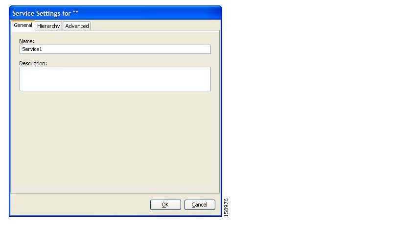
The Service Settings dialog box appears.
Figure 7-1
Step 3
Step 4
Step 5
Step 6
Note
Step 7
The Service Settings dialog box closes.
The service is added to the service tree as a child to the service you selected in the hierarchy.
Defining Hierarchical Settings for a Service
Step 1
The Hierarchy tab opens.
Figure 7-2
Step 2
Step 3
The name in the read-only Global counter of this service field changes to reflect your choice.
The Counter Index drop-down list is enabled.
(Optional) Select a value for the counter index from the Counter Index drop-down list.
Note
Step 4
The name in the read-only Subscriber counter of this service field changes to reflect your choice.
The Counter Index drop-down list is enabled.
(Optional) Select a value for the counter index from the Counter Index drop-down list.
Note
Step 5
Note
Step 6
The Service Settings dialog box closes.
The service is added to the service tree as a child to the service selected in the Parent Service drop-down list.
Setting the Service Index
Step 1
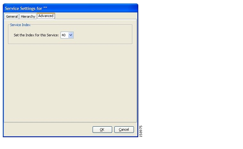
The Advanced tab opens.
Figure 7-3
Step 2
The service index must an integer in the range 1 to 499; zero is reserved for the default service.
Note
Step 3
The Service Settings dialog box closes.
The service is added to the service tree as a child to the service selected in the Parent Service drop-down list.
Viewing Services
You can view a hierarchy tree of all existing services and see their associated service elements.
Step 1
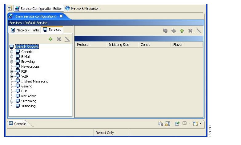
The Services tab appears.
Figure 7-4
A list of all services is displayed in the service tree (left pane).
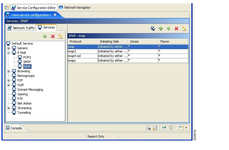
Step 2
A list of all service elements defined for this service is displayed in the right (Service Element) pane.
Figure 7-5
Step 3
( Edit Service).
The Service Settings dialog box appears.
Editing Services
You can modify the parameters of a service, even those included in the Console installation.
To add, modify, or delete service elements, see Managing Service Elements.
Step 1
Step 2
The Service Settings dialog box appears.
Step 3
Step 4
Step 5
The Hierarchy tab opens.
a.
b.
The name of the parent service's counter is displayed in the Global counter used by this service field.
c.
–
The name in the read-only Global counter of this service field changes to reflect your choice.
The Counter Index drop-down list is enabled.
Note
d.
The name of the parent service's counter is displayed in the Subscriber counter used by this service field.
e.
Check the Map this Service to an exclusive Subscriber usage counter check box.
The name in the read-only Subscriber counter of this service field changes to reflect your choice.
The Counter Index drop-down list is enabled.
f.
A default value of the counter index is provided by the system. Do not modify this value.
Step 6
a.
The Advanced tab opens.
b.
The service index must an integer in the range 1 to 499; zero is reserved for the default service.
Note
Step 7
The Service Settings dialog box closes.
The changes to the service are saved.
Deleting Services
You can delete all services, even those in the Console installation, with the exception of the default service.
Step 1
Step 2
( Delete Service).
Step 3
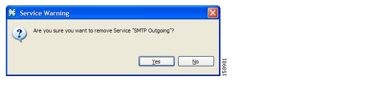
Figure 7-6
Step 4
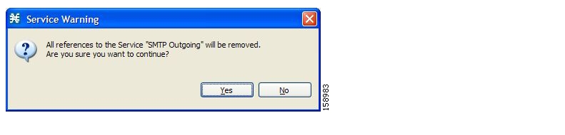
•
Figure 7-7
Click Yes.
The service is deleted and is no longer displayed in the service tree. Any rules for the service are also deleted.
Children of the deleted service are not deleted; they move up one level in the service tree.
Managing Service Elements
A service is a collection of service elements; to complete the definition of a service, you must define its service elements. A service element maps a specific protocol, initiating side, zone, and flavor to the selected service.
For more information, see Managing Protocols, Managing Zones, and Managing Flavors.
A service configuration can contain up to 10,000 service elements. Every service element must be unique.
A traffic flow is mapped by a service element to the service element's service if it meets all five of the following criteria:
•
•
•
•
•
Adding Service Elements
When necessary, you can add new service elements to a service. (The most useful service elements are included in the Console installation.) A service may have any number of service elements (subject to the limit of 10,000 service elements per service configuration).
Note
DETAILED STEPS
Step 1
Step 2
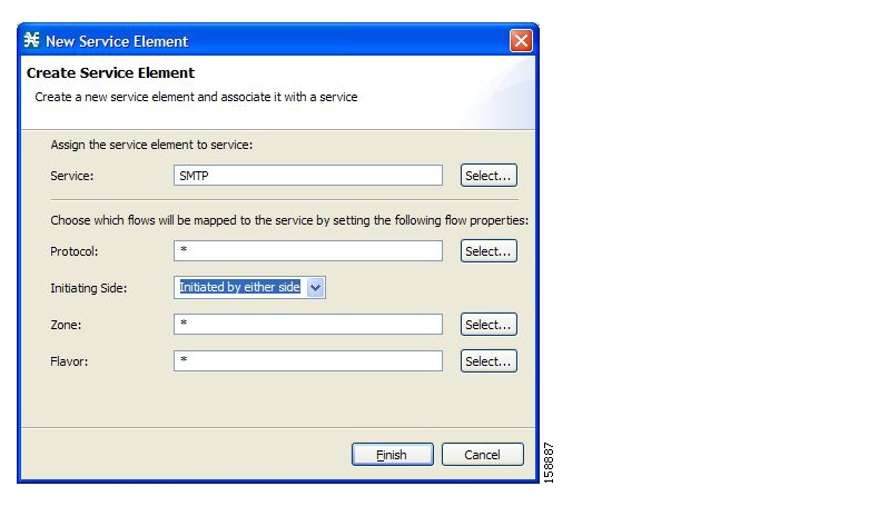
The New Service Element dialog box appears.
Figure 7-8
Step 3
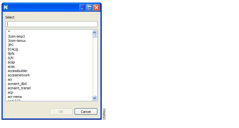
The Select a Service dialog box appears, displaying a list of all services.
Figure 7-9
Step 4
Step 5
The Select a Service dialog box closes.
The selected service is displayed in the Service field of the New Service Element dialog box.
Step 6
Note
The Select a Protocol dialog box appears, displaying a list of all protocols.
Figure 7-10
Step 7
Step 8
The Select a Protocol dialog box closes.
The selected protocol is displayed in the Protocol field of the New Service Element dialog box.
Step 9
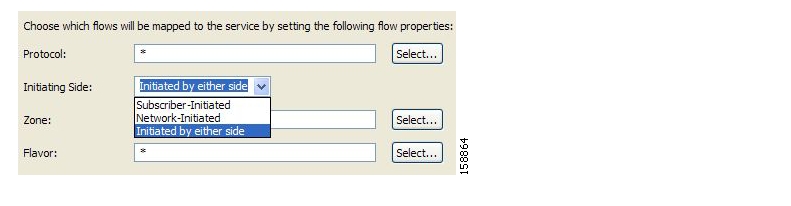
Figure 7-11
Step 10
•
•
•
Step 11
Note
The Select a Zone dialog box appears, displaying a list of all zones.
Figure 7-12
Step 12
Step 13
The Select a Zone dialog box closes.
The selected zone is displayed in the Zone field of the New Service Element dialog box.
Step 14
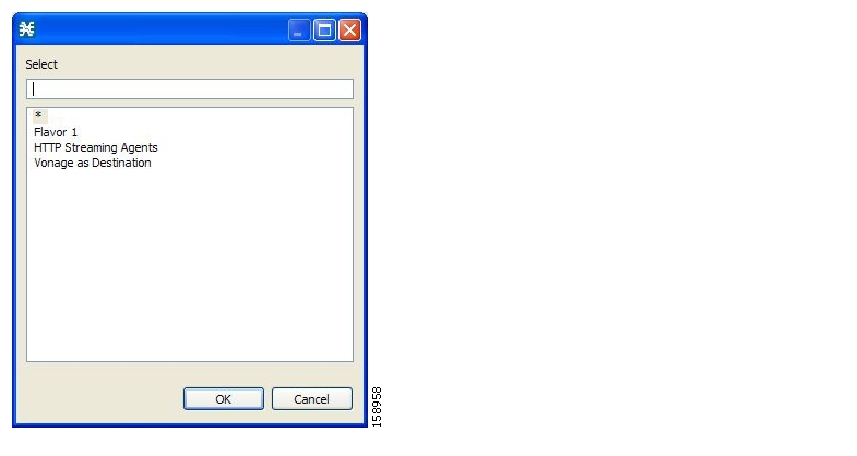
The default value (an asterisk, *) means that no flavor checking is performed when testing if a flow maps to this service element.
The Select a Flavor dialog box appears, displaying a list of all flavors.
Figure 7-13
Step 15
Step 16
The Select a Flavor dialog box closes.
The selected flavor is displayed in the Flavor field of the New Service Element dialog box.
Step 17
The New Service Element dialog box closes.
The new service element is added to the service.
A new row, representing the service element, is added to the service element list in the Service Elements pane.
Duplicating Service Elements
Duplicating an existing service element is a useful way to add a new service element similar to an existing service element. It is faster to duplicate a service element and then make changes than to define the service element from scratch.
Note
To duplicate a service element:
Step 1
A list of associated service elements is displayed in the Service Elements pane.
Step 2
Step 3
(Duplicate Service Element).
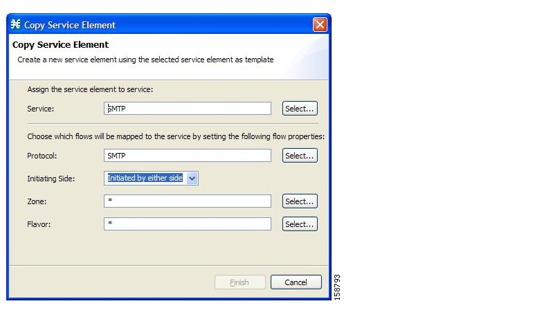
The Copy Service Element dialog box appears.
Figure 7-14
Step 4
Note
Editing Service Elements
You can modify all service elements, even those included in the Console installation.
Note
To edit a service element:
Step 1
A list of associated service elements is displayed in the Service Elements pane.
Step 2
Step 3
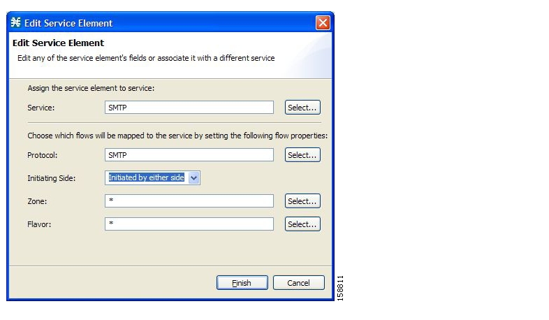
The Edit Service Element dialog box appears.
Figure 7-15
Step 4
The Select a Service dialog box appears, displaying a list of all services.
Step 5
Step 6
The Select a Service dialog box closes.
The selected service is displayed in the Service field of the Edit Service Element dialog box.
Step 7
Note
The Select a Protocol dialog box appears, displaying a list of all protocols.
Step 8
Step 9
The Select a Protocol dialog box closes.
The selected protocol is displayed in the Protocol field of the Edit Service Element dialog box.
Step 10
Step 11
•
•
•
Step 12
Note
The Select a Zone dialog box appears, displaying a list of all zones.
Step 13
Step 14
The Select a Zone dialog box closes.
The selected zone is displayed in the Zone field of the Edit Service Element dialog box.
Step 15
Note
The Select a Flavor dialog box appears, displaying a list of all flavors.
Step 16
Step 17
The Select a Flavor dialog box closes.
The selected flavor is displayed in the Flavor field of the Edit Service Element dialog box.
Step 18
The Edit Service Element dialog box closes.
The changes to the service element are saved.
The changes to the service element appear in the service element list in the Service Elements pane.
Deleting Service Element
You can delete all service elements, even those included in the Console installation.
To delete a service element:
Step 1
A list of associated service elements is displayed in the Service Elements pane.
Step 2
Step 3
A Service Warning message appears.
Figure 7-16
Step 4
The service element is deleted and is no longer part of the selected service.
Moving Service Elements
You can move an existing service element from one service to a different service.
To move a service element:
Step 1
A list of associated service elements is displayed in the Service Elements pane.
Step 2
Step 3
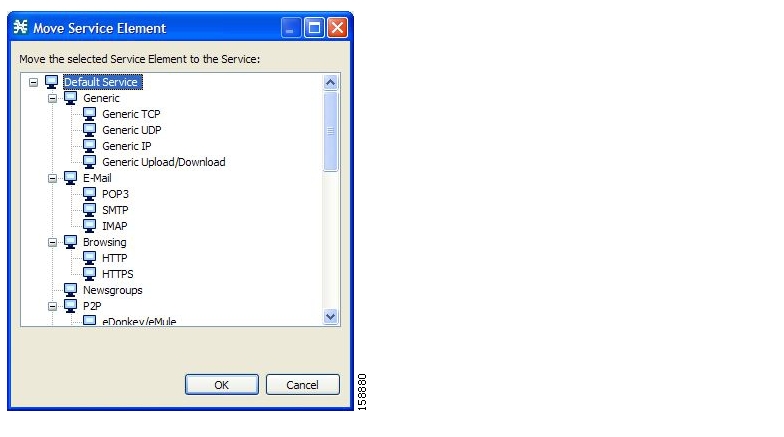
( Move Service Element to Another Service).
The Move Service Element dialog box appears, displaying the complete service tree.
Figure 7-17
Step 4
Step 5
The Move Service Element dialog box closes.
The service element is moved to the selected service.
Managing Protocols
A protocol is composed of an application protocol signature, the destination port or ports, a unique name, and an optional description.
Protocols are used to define service elements (see Managing Service Elements ).
You can add new protocols (for example, to classify a new gaming protocol that uses a specific port). You can also edit or delete existing ones.
A service configuration can contain up to 10,000 protocols.
SCA BB supports many commercial and common protocols. For a complete list of protocols included with the current release of SCA BB, see "Protocols" in the "Default Service Configuration Reference Tables" chapter of the Cisco Service Control Application for Broadband Reference Guide. As new protocols are released, Cisco provides files containing the new protocol signatures so that you can add the signatures to your service configuration. (See Adding Signatures to a Service Configuration.)
Viewing Protocols
•
How to View Protocols
You can view a list of all protocols and their associated protocol elements.
The protocols are listed in ASCII sort order (that is, 0 ... 9, A ... Z, a ... z).
The protocol elements are not sorted; they are listed in the order in which they were added to the protocol.
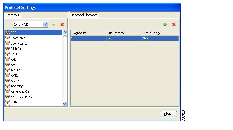
Step 1
The Protocol Settings dialog box appears.
Figure 7-18
The Protocols tab displays a list of existing protocols.
Step 2
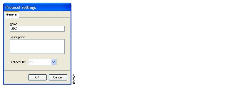
a.
The Protocol Settings dialog box appears, displaying the protocol name, description, and ID.
Figure 7-19
b.
The Protocol Settings dialog box closes.
Step 3
protocol elements are displayed in the Protocol Elements tab.
Step 4
The Protocol Settings dialog box closes.
Filtering the List in the Protocols View Tab
How to Filter the List in the Protocols View Tab
You can filter the protocols by type, so that the Protocols tab displays only the selected type of protocol.
There are nine categories of protocols:
•
•
•
•
•
•
•
•
•
•
Note
Step 1
The Protocol Settings dialog box appears.
Step 2
The protocols of the selected type appear in the Protocols tab.
Step 3
Step 4
Note
Adding Protocols
You can add new protocols to a service configuration, subject to the limit of 10,000 protocols per service configuration.
Step 1
The Protocol Settings dialog box appears.
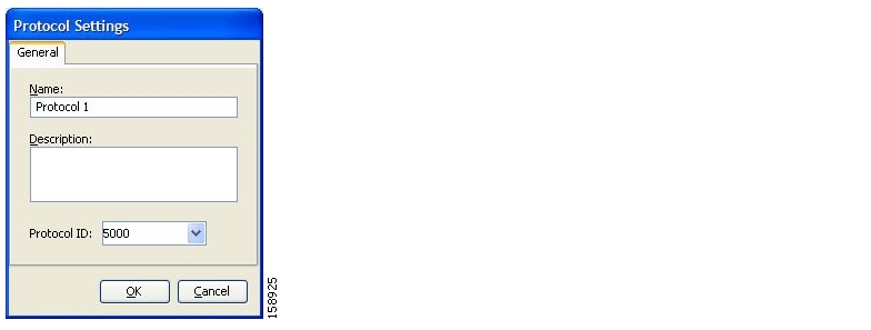
Step 2
The Protocol Settings dialog box appears.
Figure 7-20
Step 3
Step 4
The protocol ID must be an integer in the range 5000 to 9998; lower values are reserved for protocols provided by SCA BB.
Note
Step 5
The Protocol Settings dialog box closes.
The new protocol is displayed in the Protocols tab. You can now add protocol elements to it. See Adding Protocol Elements.
Editing Protocols
You can modify the parameters of a protocol, even those included in the Console installation.
To add, modify, or delete protocol elements, see Managing Protocol Elements.
Step 1
The Protocol Settings dialog box appears.
Step 2
The Protocol Settings dialog box appears.
Figure 7-21
Step 3
•
•
The protocol ID must be an integer in the range 5000 to 9998; lower values are reserved for protocols provided by SCA BB.
Note
Step 4
The Protocol Settings dialog box closes.
The new values of the protocol parameters are saved.
Step 5
The Protocol Settings dialog box closes.
Deleting Protocols
You can delete all protocols, even those included in the Console installation.
Step 1
The Protocol Settings dialog box appears.
Step 2
Step 3
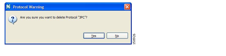
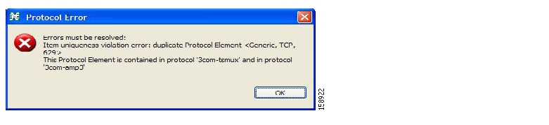
A Protocol Warning message appears.
Figure 7-22
Step 4
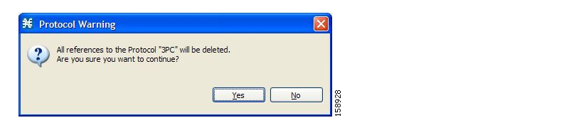
•
Figure 7-23
•
The Protocol is deleted from the Protocols tab.
Step 5
The Protocol Settings dialog box closes.
Managing Protocol Elements
A protocol is a collection of protocol elements .
To complete the definition of a protocol, you must define its protocol elements. A protocol element maps a specific signature, IP protocol, and port range to the selected protocol. Every protocol element in a service configuration must be unique.
A traffic flow is mapped to a specific protocol if it meets all four of the following criteria:
•
•
•
•
Adding Protocol Elements
You can add any number of protocol elements to a protocol.
Note
DETAILED STEPS
Step 1
The Protocol Settings dialog box appears.
Step 2
Step 3
A protocol element is added to the protocol.
A new row, representing the protocol element, is added to the protocol element list in the Protocol Element tab.
Step 4
Note
Figure 7-24
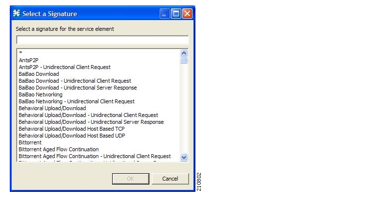
Step 5
Note
Step 6
The Select a Signature dialog box closes.
The selected signature is displayed in the Signature cell of the Protocol Settings dialog box.
Step 7
Note
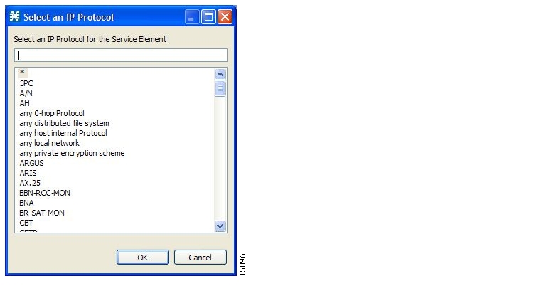
The Select an IP Protocol dialog box appears, displaying a list of all IP protocols.
Figure 7-25
Step 8
Step 9
The Select an IP Protocol dialog box closes
The selected IP protocol is displayed in the IP Protocol cell of the Protocol Settings dialog box.
Step 10
Note
Only a flow whose port matches one of these ports will be mapped to this protocol element.
The protocol element is defined.
Step 11
•
Figure 7-26
a.
b.
c.
The Protocol Settings dialog box closes.
Editing Protocol Elements
You can modify all protocol elements, even those included in the Console installation.
Note
Step 1
The Protocol Settings dialog box appears.
Step 2
Step 3
Step 4
The Select a Signature dialog box appears.
Step 5
Step 6
The Select a Signature dialog box closes.
Step 7
The Select an IP Protocol dialog box appears.
Step 8
Step 9
The Select an IP Protocol dialog box closes.
Step 10
Changes to the protocol element are saved as you make them.
Step 11
•
a.
b.
c.
The Protocol Settings dialog box closes.
Deleting Protocol Elements
You can delete all protocol elements, even those included in the Console installation.
Step 1
The Protocol Settings dialog box appears.
Step 2
Step 3
Step 4
A Protocol Warning message appears.
Figure 7-27
Step 5
The protocol element is deleted from the Protocol Elements tab.
Step 6
The Protocol Settings dialog box closes.
Managing Zones
A zone is a collection of destination IP addresses; usually the addresses in one zone will be related in some way.
Zones are used to classify network sessions; each network session is assigned to a service element based on its destination IP address.
A service configuration can contain up to 10,000 zone items. Every zone item must be unique.
Viewing Zones
You can view a list of all zones and their associated zone items.
Step 1
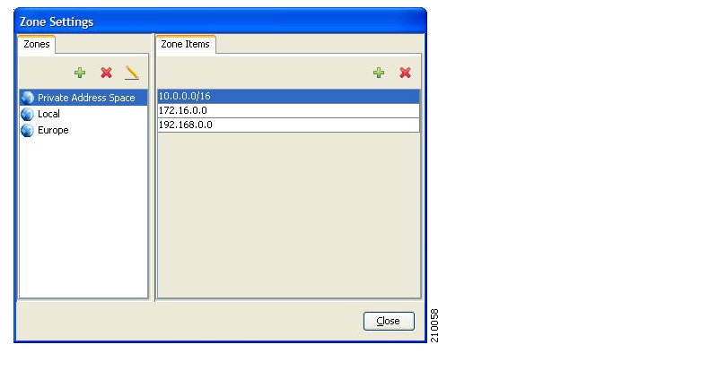
The Zone Settings dialog box appears.
The Zones tab displays a list of all zones. The first zone in the list is selected, and its zone items are displayed in the Zone Items tab.
Figure 7-28
Step 2
The zone items of the selected zone are displayed in the Zone Items tab.
Step 3
The Zone Settings dialog box closes.
Adding Zones
Step 1
The Zone Settings dialog box appears.
Step 2
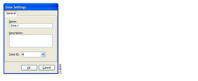
The Zone Settings dialog box appears.
Figure 7-29
Step 3
Step 4
The zone ID must be a positive integer in the range 1 to 32767.
Note
Step 5
The Zone Settings dialog box closes.
The new zone is added to the Zones tab. You can now add zone items. (See Adding Zone Items.)
Editing Zones
You can modify zone parameters at any time.
To add, modify, or delete zone items, see Managing Zone Items.
Step 1
The Zone Settings dialog box appears.
Step 2
Step 3
The Zone Settings dialog box appears.
Step 4
•
•
The zone ID must be a positive integer in the range 1 to 32767.
Note
Step 5
The Zone Settings dialog box closes.
The new values of the zone parameters are saved.
Step 6
The Zone Settings dialog box closes.
Deleting Zones
You can delete any or all zones.
Step 1
The Zone Settings dialog box appears.
Step 2
Step 3
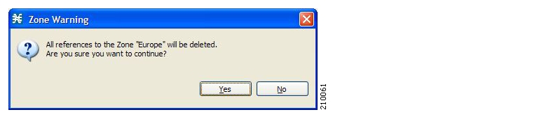
A Zone Warning message appears.
Figure 7-30
Step 4
•
Figure 7-31
•
Every service element that references the selected zone is deleted.
The zone is deleted and is no longer displayed in the Zones tab.
Step 5
The Zone Settings dialog box closes.
Managing Zone Items
A zone is a collection of related zone items .
A zone item is an IP address or a range of IP addresses.
A service configuration can contain up to 10,000 zone items. Every zone item must be unique.
Adding Zone Items
You can add any number of zone items to a zone (subject to the limitation of 10,000 zone items per service configuration).
Step 1
The Zone Settings dialog box appears.
Step 2
Step 3
A new line is added to the Zone Items table.
Step 4
Valid values are single IP addresses (for example, 63.111.106.7) or a range of IP addresses (for example, 194.90.12.0/24).
Step 5
Step 6
•
a.
b.
c.
The Zone Settings dialog box closes.
Deleting Zone Items
Step 1
The Zone Settings dialog box appears.
Step 2
Step 3
Step 4
The zone item is deleted.
Step 5
The Zone Settings dialog box closes.
Managing Protocol Signature
•
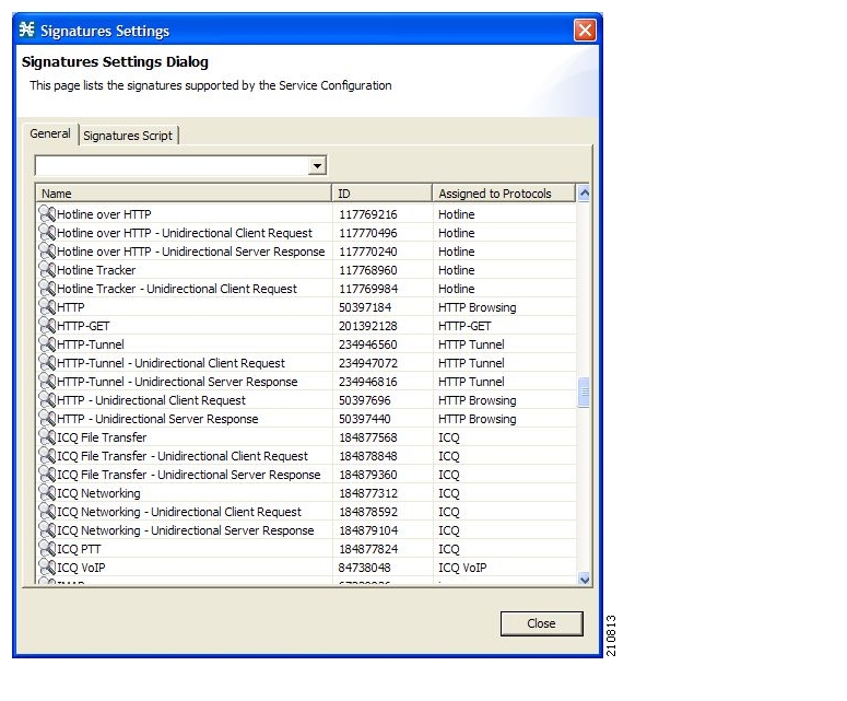
Viewing Signatures
You can view a list of all signatures and the protocol to which each is assigned.
Step 1
The Signatures Settings dialog box appears.
Figure 7-32
Step 2
The Signatures Settings dialog box closes.
Filtering Signature Settings
How to Filter Signature Settings
You can filter the signature by type, so that the Signatures Settings dialog box lists only the selected type of signature.
There are eight categories of signatures:
•
•
•
•
•
•
•
•
Note
Step 1
The Signatures Settings dialog box appears.
Step 2
The signatures of the selected type appear in the dialog box.
Step 3
The Signatures Settings dialog box closes.
Dynamic Signatures
New protocols are being introduced all the time. Dynamic signatures is a mechanism that allows new protocols to be added to the protocol list and, from there, to service configurations. This is especially useful for classifying the traffic of a new protocol (for example, a new P2P protocol in a P2P-Control solution).
•
•
•
Dynamic Signature Script Files
Dynamic signatures are provided in special Dynamic Signatures Script (DSS) files that you can add to a service configuration using either the Console or the Service Configuration API. After a DSS file is imported into a service configuration, the new protocols it describes:
•
•
•
To simplify the configuration of new protocols added by a DSS, the DSS may specify a Buddy Protocol for a new protocol. If, when loading a DSS, the application encounters the Buddy Protocol, it automatically duplicates the set of service elements that use the Buddy Protocol, and replaces all references to the Buddy Protocol with references to the new protocol. The association of the new protocol to services will match that of the Buddy Protocol.
The following configuration actions are performed automatically when you import a DSS into a service configuration:
•
•
•
•
The import procedure preserves all service and protocol settings.
Note
DSS files are periodically released by Cisco or its partners in accordance with customer requirements and market needs. DSS files contain new protocols and signatures, and update previously defined signatures. Updating a service configuration with the new DSS is explained in Adding Signatures to a Service Configuration.
Note
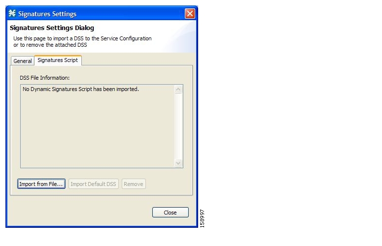
Viewing Current Dynamic Signatures Information
Step 1
The Signatures Settings dialog box appears.
Step 2
The Signatures Script tab opens.
•
Figure 7-33
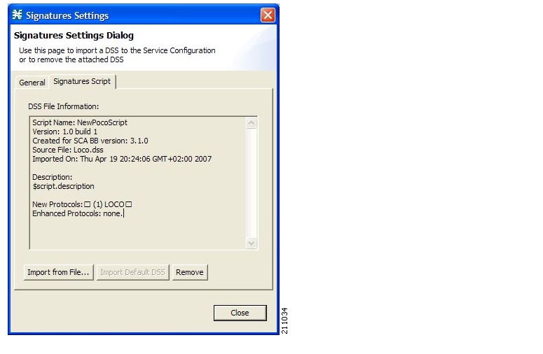
•
Figure 7-34
Step 3
The Signatures Settings dialog box closes.
Adding Signatures to a Service Configuration
•
Adding Signatures to a Service Configuration
You can import signatures into a service configuration from a DSS file provided by Cisco or one of its partners (described in this section), or from a DSS file that you have created or modified using the Signature Editor tool ( see Information About Managing DSS Files ).
Note
Step 1
The Signatures Settings dialog box appears.
Step 2
The Signatures Script tab opens.
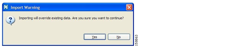
Step 3
An Import Warning message appears.
Figure 7-35
Step 4
The Import from file dialog box appears.
Step 5
The Import from file dialog box closes.
The signatures in the DSS file are imported into the service configuration.
Information about the imported signatures and their DSS file is displayed in the Signatures Settings dialog box.
Step 6
The Signatures Settings dialog box closes.
Removing Dynamic Signatures
You can remove the installed dynamic signatures from a service configuration.
Note
Step 1
The Signatures Settings dialog box appears.
Step 2
The Signatures Script tab opens.
Step 3
A Dynamic Signature Script Confirmation message appears.
Figure 7-36
Step 4
•
Figure 7-37
•
Every service element that references a protocol whose signature is included in the imported DSS file is deleted.
The dynamic signatures are removed from the service configuration.
The Remove button is dimmed.
If the dynamic signatures were imported from the default DSS file, the Import Default DSS button is enabled.
Step 5
The Signatures Settings dialog box closes.
The Default DSS File
Whenever a protocol pack becomes available from Cisco (or one of its partners), you should update offline service configurations (stored as PQB files on the workstation). The Protocol Packs is provided as either an SPQI file or a DSS file.
Either offer updates automatically to every service configuration created or edited at the workstation or apply them from the workstation to the SCE platform. You make the latest update available by installing the most recent DSS or SPQI file as the default DSS file. You can install the file on the workstation either from the Console or by using Information About The SCA BB Signature Configuration Utility.
•
•
Note
Setting the Default DSS File
The default DSS file should normally be the latest protocol pack provided by Cisco (or one of its partners). If necessary, modify the protocol pack using the Signature Editor tool (see Editing DSS Files ) to add signatures of new protocols until they become available from Cisco.
Whenever a new protocol pack becomes available, set it as the default DSS file. There is no need to clear the current default DSS file; it will be overwritten by the new protocol pack.
Step 1
The Preferences dialog box appears.
Step 2
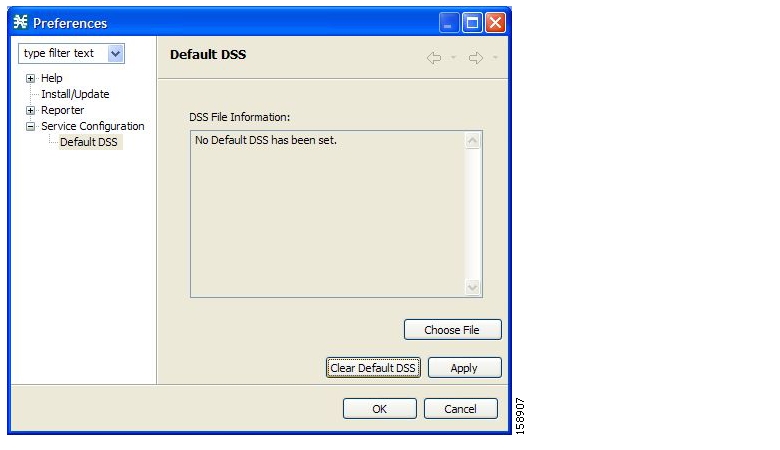
The Default DSS area opens in the right pane of the dialog box.
Figure 7-38
Step 3
An Open dialog box appears.
Step 4
Step 5
Step 6
The Open dialog box closes.
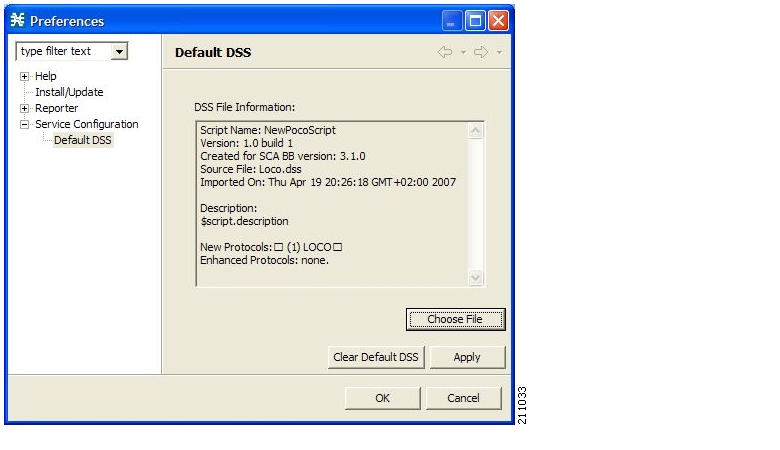
Information about the default DSS file is displayed in the Default DSS area of the Preferences dialog box.
Figure 7-39
Step 7
The DSS file is copied to C:\Documents and Settings\<user name>\.p-cube\default3.1.0.dss as the default DSS file.
The Preferences dialog box closes.
Clearing the Default DSS File:
Step 1
The Preferences dialog box appears.
Step 2
The Default DSS area opens in the right pane of the dialog box.
Step 3
The default DSS file, C:\Documents and Settings\<user name>\.p-cube\default3.1.0.dss is deleted.
All information is deleted from the Default DSS area.
Note
Step 4
The Preferences dialog box closes.
Importing Dynamic Signatures from the Default DSS File
If a default DSS file is installed, the application offers to import the dynamic signatures from the file when you create a new service configuration or when you open an existing service configuration that has not imported the signatures. Alternatively, you can manually import the dynamic signatures.
Step 1
A Default Signature message appears.
Figure 7-40
Step 2
•
•
Importing the Default DSS File Manually:
Step 1
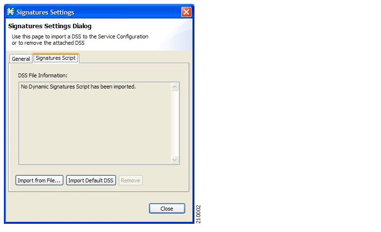
The Signatures Settings dialog box appears
Step 2
The Signatures Script tab opens, with the Import Default DSS button enabled.
Figure 7-41
Step 3
An Import Warning message appears.
Figure 7-42
Step 4
The signatures in the default DSS file are imported into the service configuration.
The Import Default DSS button is dimmed.
Information about the imported signatures and the default DSS file is displayed in the Signatures Settings dialog box.
Step 5
The Signatures Settings dialog box closes.
Managing Flavors
Flavors are advanced classification elements that are used to classify network sessions.
Flavors are based on specific Layer 7 properties. For example, users can associate an HTTP flow with a service based on different parts of the destination URL of the flow.
Flavors are supported only for small number of protocols, and for each such protocol there are different applicable flavor types. Flavor types are listed in the table in the following section.
There is a maximum number of flavor items for each flavor type (see Maximum Number of Flavor Items per Flavor Type ). For each flavor type, every flavor item must be unique.
Note
Flavor Types and Parameters
The following table lists available flavor types.
Note
Viewing Flavors
You can view a list of all flavors and their associated flavor items.
Step 1
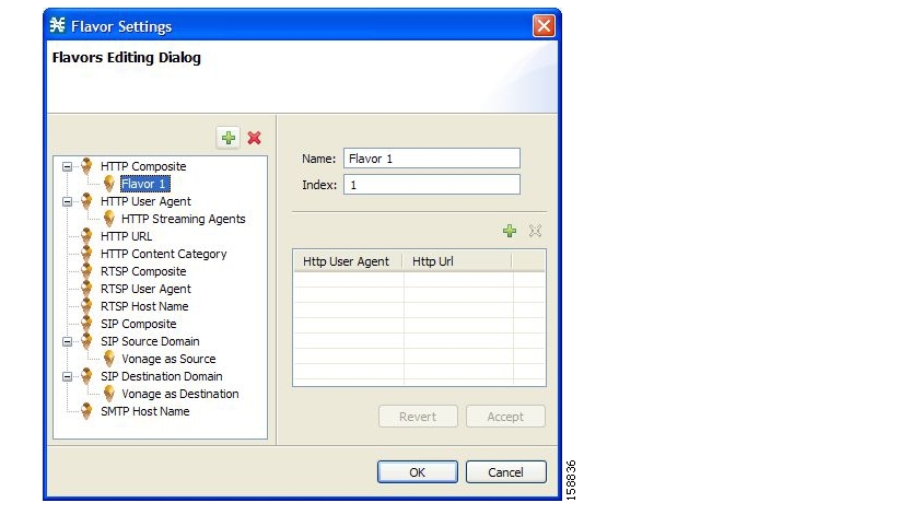
The Flavor Settings dialog box appears.
Figure 7-43
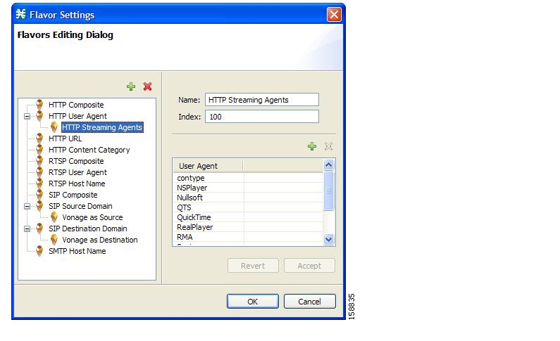
The left area displays a tree showing all flavors of each flavor type.
Step 2
Figure 7-44
The flavor items are displayed in the right area.
Step 3
The Flavor Settings dialog box closes.
Adding Flavors
You can add any number of flavors to a service configuration.
Step 1
The Flavor Settings dialog box appears.
Step 2
Enters global configuration mode.
Step 3
A new flavor of the selected type is added to the flavor tree.
Figure 7-45
Step 4
Note
Step 5
Note
The flavor index must be a positive integer in the range 1 to 32767. You have defined the flavor. You can now add flavor items. (See Adding Flavor Items.)
Editing Flavors
You can modify flavor parameters at any time.
To add, modify, or delete flavor items, see Managing Flavor Items.
Step 1
The Flavor Settings dialog box appears.
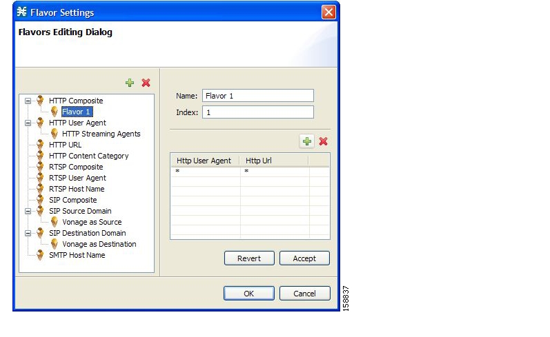
Step 2
The name and index of the flavor (and its flavor items) are displayed in the right area.
Step 3
•
•
flavor index must be a positive integer in the range 1 to 32767.
Step 4
The Flavor Settings dialog box closes.
Deleting Flavors
You can delete any or all flavors.
Step 1
EnableThe Flavor Settings dialog box appears.
Step 2
A popup menu appears.
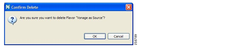
Step 3
A Confirm Delete message appears.
Figure 7-46
Step 4
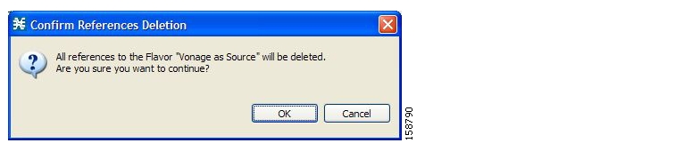
•
Figure 7-47
•
Every service element that references the selected flavor is deleted.
The flavor is deleted and is no longer displayed in the flavor tree.
Step 5
The Flavor Settings dialog box closes.
Managing Flavor Items
A flavor is a collection of related flavor items .
A flavor item is a value of a property or properties of a flow. These properties depend on the flavor type ( see Flavor Types and Parameters ).
There is a maximum number of flavor items for each flavor type (see the following section). For each flavor type, every flavor item must be unique.
Maximum Number of Flavor Items per Flavor Type
The following table lists the maximum number of flavor items for each flavor type.
Adding Flavor Items
You can add any number of flavor items to a flavor (subject to the limitation of the total number of each type of flavor item per service configuration, as listed in the previous section).
Step 1
The Flavor Settings dialog box appears.
Step 2
Step 3
Figure 7-48
A new flavor item is added to the flavor item list. The number and type of parameters in the flavor item depend on the flavor type (see Flavor Types and Parameters ).
The new flavor item has a default value of all wild cards (*, asterisks).
Step 4
•
•
a.
A Browse button is displayed in the cell.
b.
A Select dialog box appears, displaying all valid values for the parameter.
Figure 7-49
c.
d.
The Select dialog box closes.
The selected value is displayed in the cell.
Step 5
Step 6
The Flavor Settings dialog box closes.
Editing Flavor Items
Step 1
The Flavor Settings dialog box appears.
Step 2
Step 3
Step 4
•
•
a.
A Browse button is displayed in the cell.
b.
A Select dialog box appears, displaying all valid values for the parameter.
c.
d.
The Select dialog box closes.
The selected value is displayed in the cell.
Step 5
The Flavor Settings dialog box closes.
Deleting Flavor Items
Step 1
The Flavor Settings dialog box appears.
Step 2
Step 3
A popup menu appears.
Step 4
The flavor item is deleted and is no longer displayed in the flavor item list.
Step 5
The Flavor Settings dialog box closes.
Managing Content Filtering
Content filtering involves classification and control of HTTP flows according to the requested URL. The classification of the URL is performed by accessing an external database.
SCA BB provides content filtering by integrating with a SurfControl Content Portal Authority (CPA) server.
Note
•
•
•
•
•
•
•
Content Filtering Overview
The Cisco HTTP Content Filtering solution consists of:
•
•
•
The SCE application classifies the HTTP flow according to the category returned by the CPA server. This classification is then used for SCA BB traffic control and reporting. For example, users can define a rule to block browsing of the "Adult/Sexually Explicit" category or to generate reports on the volume consumed by browsing the "Kids" or "Shopping" categories.
Configuring the RDR Formatter
The SCE application communicates with the CPA client using Raw Data Records (RDRs). To enable the RDR formatter to issue HTTP categorization requests, configure the RDR formatter on the SCE platform using the SCE platform CLI:
#>RDR-formatter destination 127.0.0.1 port 33001 category number 4 priority 100For more information about configuring the RDR formatter, see the "Configuring the RDR Formatter" chapter of the Cisco Service Control Engine (SCE) Software Configuration Guide .
Installing the SurfControl CPA Server
The SurfControl CPA Server is installed on a separate server that must be accessible from the SCE platform.
The details of the installation are not within the scope of this document.
The Content Filtering CLI
You can configure content filtering using SurfControl CPA and monitored using the SCE platform Command-Line Interface (CLI). For more information about the SCE platform CLI, see the Cisco Service Control Engine (SCE) CLI Command Reference .
The commands listed here are explained in the following section.
Use the following CLI commands to configure the Cisco CPA client:
•
•
•
These commands are line interface configuration commands. To run these commands you must enter line interface configuration mode and see the SCE( config if) # prompt displayed.
Step 1
SCE#), typeconfigure.Step 2
The SCE(
config)# prompt appears.Step 3
interface LineCard 0.Step 4
The SCE(config if)# prompt appears.
Use the following CLI command in EXEC mode to monitor the status of the Cisco CPA client:
•
show interface LineCard <slot>cpa-clientDescription of CPA Client CLI Commands
The following table gives a description of the Cisco CPA client CLI commands listed in the previous section and their default values.
The following table displays the information shown when monitoring the Cisco CPA client.
Managing Content Filtering Settings
Applying HTTP URL content filtering requires the following steps in the Service Configuration Editor:
Step 1
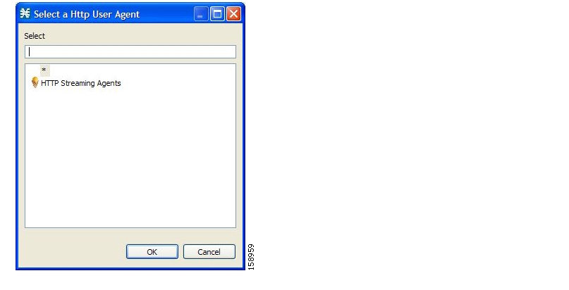
By default, SCA BB creates a separate flavor (of type HTTP Content Category) for each content category and a service element for each new flavor. A new top-level service, "HTTP Browsing with Categories", is created, comprising these service elements.
Step 2
Step 3
Step 4
Step 5
Importing Content Filtering Categories
Before you can control HTTP flows based on content, you must import an XML file provided with the installation.
After you unzip the installation package, this file is located in the URL Filtering subfolder.
You can import content filtering categories using either the File >Importmenu option or the Configuration >Content Filteringmenu option.
You cannot import content filtering categories when asymmetric routing classification mode is enabled.
Step 1
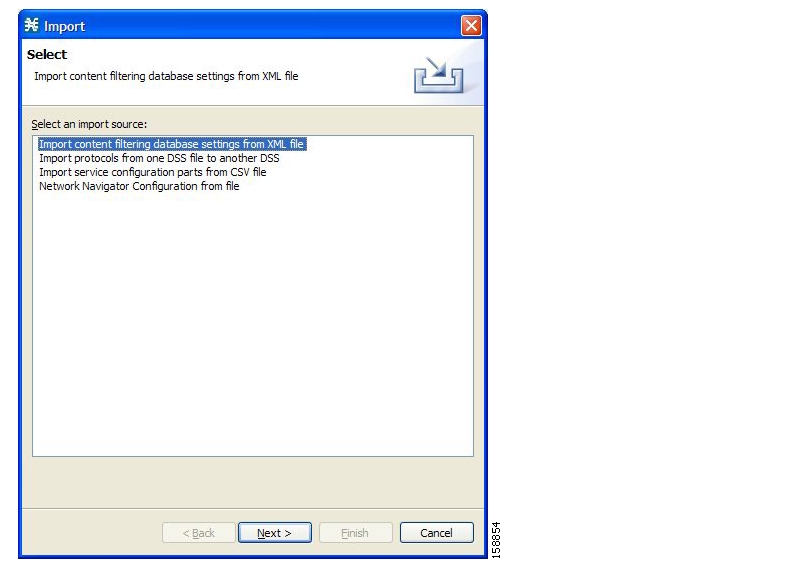
The Import dialog box appears.
Figure 7-50
Step 2
Step 3
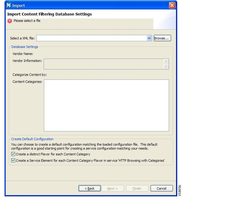
The Import Content Filtering Database Settings dialog box appears.
Figure 7-51
Step 4
An Open dialog box appears.
Step 5
Note
Step 6
The Open dialog box closes.
Information about the content of the XML file is displayed in the Database Settings pane of the Import Content Filtering Database Settings dialog box.
Step 7
•
Note
Step 8
•
Note
Step 9
The Import Content Filtering Database Settings dialog box closes.
Importing Content Filtering Categories Using the HTTP Content Filtering Settings Dialog Box
Note
Step 1
The HTTP Content Filtering Settings dialog box appears.
Step 2
The Database Settings tab opens.
Step 3
The Import Content Filtering Database Settings dialog box appears.
Step 4
Step 5
The Import Content Filtering Database Settings dialog box closes.
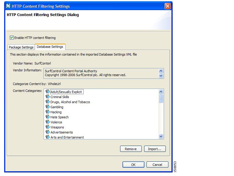
Information from the imported file is displayed in the Database Settings tab of the HTTP Content Filtering Settings dialog box.
Figure 7-52
Step 6
The HTTP Content Filtering Settings dialog box closes.
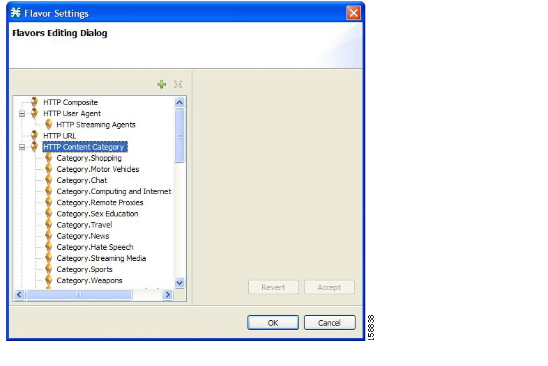
HTTP Content Category Flavors
By default, SCA BB creates a separate flavor (of type HTTP Content Category) for each content category when importing the XML file.
Figure 7-53
You can create additional HTTP Content Category Flavors that include two or more content categories. (See Adding Flavors.)
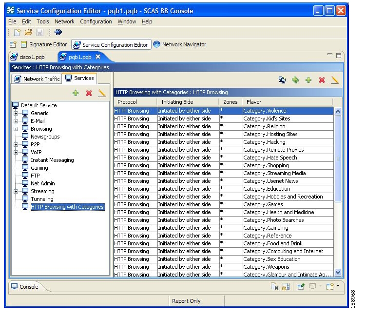
HTTP Browsing with Categories Service Elements
By default, SCA BB creates a service element for each flavor created in the previous step. A new top-level service, HTTP Browsing with Categories, is created, comprising these service elements.
Figure 7-54
Note
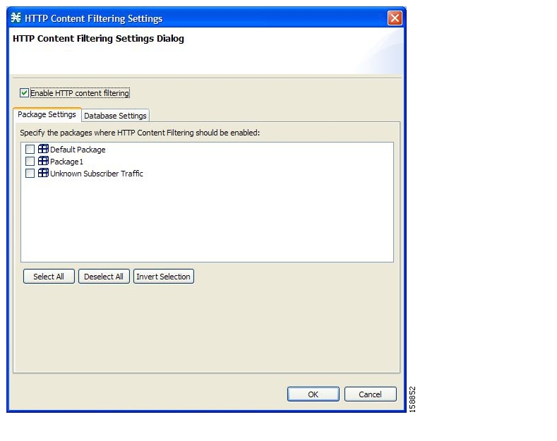
Configuring Content Filtering
You can specify the packages where content filtering will be enabled. For packages where content filtering is disabled, HTTP flows will be classified normally.
Step 1
The HTTP Content Filtering Settings dialog box appears.
The Package Settings tab displays a list of all packages defined for the current service configuration.
Figure 7-55
Step 2
Step 3
Step 4
The HTTP Content Filtering Settings dialog box closes.
Viewing Content Filtering Settings
You can view whether content filtering is enabled and to which packages content filtering is applied, and information about the content filtering vendor and the vendor's content categories.
Step 1
The HTTP Content Filtering Settings dialog box appears.
The Package Settings tab displays a list of all packages defined for the current service configuration, and shows for which packages content filtering is enabled.
Step 2
The Database Settings tab opens.
This tab displays information about the content filtering vendor and the vendor's content categories.
Step 3
The HTTP Content Filtering Settings dialog box closes.
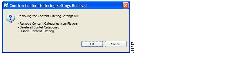
Removing Content Filtering Settings
You can remove all content filtering settings at any time.
Removing the settings:
•
•
•
Step 1
The HTTP Content Filtering Settings dialog box appears..
Step 2
The Database Settings tab opens.
Step 3
A Confirm Content Filtering Settings Removal dialog box appears.
Figure 7-56
Step 4
All content filtering settings are removed.
Vendor Name, Vendor Information, and Content Categories are deleted from the HTTP Content Filtering Settings dialog box.
Step 5
The HTTP Content Filtering Settings dialog box closes.
![]()
![]()
![]()
![]()
![]()
![]()
![]()
![]()
Posted: Wed May 30 13:24:44 PDT 2007
All contents are Copyright © 1992--2007 Cisco Systems, Inc. All rights reserved.
Important Notices and Privacy Statement.