|
|

Table Of Contents
Providing Redundancy and Reliability
Providing Redundancy and Reliability
The architecture of the network determines the approaches used to ensure service. This chapter addresses remedies for the following topologies:
Fundamental Failure Scenarios
There are five fundamental failure scenarios:
1.
A DWDM fiber cut
2.
3.
4.
5.
These scenarios are referred to by number in the following discussion. The redundancy options discussed in this chapter were selected for their ability to deal with any one of these failure modes. Multiple simultaneous failures are not considered. For a discussion of particular link failures and remedies, see Link Failure Modes.
Note
For an illustration of link failure modes and their responses, see Switch in Dhub: Ethernet Troubleshooting Examples.
Note
Switch in Dhub
There are two redundancy options for the switch-in-Dhub topology:
These are discussed in detail below.
Headend Switch Protection
Headend switch protection is the most redundant—but most costly— failover mechanism for protection in this solution. This protection mechanism relies on two fibers between headend and Dhub sites, two headend switches, and two sets of optical multiplexers/OSCs. Depending on the capabilities of the VoD server, the VoD streams from the VoD server will either be(1) sent from one of two GE ports on the VoD server, or (2) replicated at the optical layer by means of an optical splitter. On VoD servers that are capable of GE failover, two GE ports will be used on the VoD server, with video being transmitted on one of the two ports. Figure 4-1 illustrates the topology for headend switch protection for VoD servers that support GE failover. Table 1-2 shows which VoD servers are capable of GE port failover.
Note
Figure 4-1 Headend Switch Protection: GE Failover on the VoD Server
On VoD servers that are not capable of GE failover, an optical splitter can be used to split the optical signal between the VoD server and headend switches. Figure 4-2 illustrates the topology for headend switch protection with optical splitting.
Figure 4-2 Headend Switch Protection: Optical Splitting
In this failover scenario, the two headend switches are connected to each other through an EtherChannel group that has the same number of optical links as the headend-to-Dhub connections. The same combination of EtherChannel groups and IP interfaces is configured on both the links between the headend switches and the headend-to-Dhub connections. On VoD servers that support failover, the GE ports facing the VoD servers on each of the two headend switches are configured as separate routable interfaces, and an IP routing protocol (OSPF in Release 1.0 and Release 1.1 of the Cisco Gigabit-Ethernet Optimized VoD Solution) is enabled on these interfaces. The VoD servers must be capable of supporting multiple IP subnets; the servers must also support OSPF on the linecards, as OSPF must also be enabled on the VoD server line cards. (See OSPF.)
When either a GE link is cut or a headend switch fails, OSPF routes traffic from one set of GE links to another. The OSPF cost metric must be configured to be higher for one VoD server's GE link than for the other. The lower-cost GE link will be the primary GE link, and the higher-cost link will be the standby link.
On VoD servers that do not support GE failover, the two headend switches must run HSRP between the GE interfaces connected to the VoD server. (See Using and Monitoring HSRP.) One switch will be the active HSRP node, and the other will be the standby node. The standby HSRP node will have its GE port disabled, so no video will be passed through it.
OSPF must be enabled on each EtherChannel interface on the headend switches, as well as on the Dhub switch. The headend switches and the Dhub switches for all Dhubs connected to the headend must share the same OSPF process ID (PID). On VoD servers that support GE failover, the GE interfaces on the VoD server must also share the same OSPF PID.
Link Failure Modes
The following sections show how the system works under the five scenarios listed in Fundamental Failure Scenarios. Those modes can be expanded to take into account two basic types of link failure:
•
•
Table 4-1 Detailed Summary of Link Failure Modes
1.
Loss of the bidirectional link brings down the entire EtherChannel.
2.
3.
4.
See Link Failure Mode 4.
5.
6.
7.
8.
See Link Failure Mode 8.
9.
See Link Failure Mode 9.
Details are addressed in the following sections.
Link Failure Mode 4
If the all of the ports connecting the headend and Dhub switches fail, the headend switch immediately learns that the ports are down. OSPF reroutes traffic through the alternate headend switch to the Dhub switch.
Link Failure Modes 5, 6, and 7
The behavior of the network in these three scenarios depends on whether the GE ports that are affected (1) are part of an EtherChannel group, or (2) are physical Layer 3 interfaces that are part of an IP load-balancing group.
In case (1), the streams carried on those ports will be lost. EtherChannel will not redistribute the load if a unidirectional link is cut, because the port-layer keep-alive protocol is disabled for unidirectional links. Because of this, the headend EtherChannel logic will not recognize the loss of a member EtherChannel link, and will therefore not redistribute the EtherChannel load across the remaining member links. When new video sessions are initiated, sessions whose packets are hashed to the failed port(s) will be dropped at the headend switch. There is no automated failover for this type of scenario.
In case (2), the Dhub switch will learn immediately that the interfaces are down. However, UDLR will not relay this information to the feed side of the interface. (See UDLR.) Since OSPF is a unidirectional routing protocol, OSPF link-state updates will not cause the headend switch to remove the failed interfaces from the switch's RIB (routing information base). In OSPF, the mechanism used to inform the headend switch that its unidirectional feed interface is down is the hello protocol. In normal OSPF operation, the hello protocol is not used to detect link failure. To get the OSPF hello protocol to detect a link failure in the headend switch in a timely manner, OSPF fast hello must be enabled in Cisco IOS. OSPF fast hellos cause the feed interface to send a hello packet periodically to the Dhub switch, which then returns the packet to the feed interface on any directly connected return link. When the fiber is cut, OSPF hellos are not received by the Dhub switch, and so are not be returned to the headend switch.
The failure of the headend switch to receive hello packets causes the feed interface to go down on the that switch. Consequently, IP load balancing will redistribute the load across the remaining interfaces in the IP load-balancing group. For reasons of economy, the traffic load on an interface is often at or near 100%, and a link failure with this level of oversubscription can result in a loss of video on all interfaces. To prevent this type of failure from affecting video, the capacity of the IP load-balancing group can be overprovisioned by using N additional GE links, to provide for N port failures.
Link Failure Mode 8
If a subset of the ports connecting the two headend switches fail at the headend switch, either the EtherChannel logic or OSPF detects the failure immediately—depending on whether the GE ports that are affected are part of an EtherChannel group or are physical Layer 3 interfaces that are part of an IP load-balancing group. In either case, the EtherChannel or IP load-balancing logic will redistribute the load across the remaining links in the load-balancing group. To prevent this type of failure from affecting video, the capacity of the EtherChannel or IP load-balancing group can be over provisioned by using N additional GE links to take into account N port failures.
Link Failure Mode 9
In topologies where the VoD servers do not support GE failover, HSRP will detect the failure by means of the HSRP keep alive protocol. (See HSRP Redundancy Scenarios.) When HSRP detects the failure on the standby switch, it switches the GE interface(s) on the standby switch from standby to active. IP routing on this headend switch should have determined that the lowest-cost path to the QAM devices is through a directly connected switch interface. As a result, video streams will be routed to the Dhub switch through this interface.
In topologies where VoD servers support GE failover, a headend switch failure is detected as a set of interface failures by OSPF on the standby headend switch and the VoD server. OSPF reroutes video streams from the primary headend switch to the standby headend switch.
HSRP Redundancy Scenarios
This section presents a detailed illustration of three switch-in-Dhub HSRP redundancy scenarios tested as part of the Cisco Gigabit-Ethernet Optimized VoD Solution, Release 1.0 and Realease 1.1.
•
•
•
Note
Switch in Dhub: HSRP without UDLR
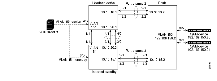
Figure 4-3 illustrates a scenario where HSRP is used without UDLR.
Figure 4-3 Switch in Dhub: HSRP without UDLR
Scenario Characteristics
Note the following key characteristics of this scenario:
•
–
–
•
•
•
Primary Headend Switch: Configuration Excerptip address 192.168.151.100 255.255.255.0no ip redirectsservice-policy input setDSCPstandby ip 192.168.151.2standby timers 1 2standby priority 100standby preemptStandby Headend Switch: Configuration Excerptinterface Vlan151ip address 192.168.151.101 255.255.255.0no ip redirectslogging event link-statusstandby ip 192.168.151.2standby timers 1 2standby priority 10
Note
http://www.cisco.com/univercd/cc/td/doc/cisintwk/ics/cs009.htm•
ip access-list extended acl_standby_linkremark Stop video traffic on standby_link (g1/1)permit icmp any anyFailure Recovery Time
Table 4-2 lists a variety of failures and time to recover from them for this scenario.
Note
Table 4-2 Switch in Dhub: Recovery Times for HSRP without UDLR Scenario
DWDM fiber
Pulled DWDM fiber between headend and Dhub without interface tracking activated. (See Switch in Dhub: HSRP with Interface Tracking.)
5-7
This is the time for OSPF to switch to backup path.
Dhub switch linecard
Pulled linecard serving Port-channel1 to Dhub.
Headend switch linecard
GBIC or GE fiber on bidirectional link
Pulled GBIC or GE fiber (same effect).
5-7
GBIC or GE fiber on unidirectional link
No recovery.
Headend switch
Turned power off.
2
Preempting the headend switch resulted in a 7-sec outage.
Configuration Examples
For sample configurations for this scenario, see HSRP without UDLR.
Switch in Dhub: HSRP with UDLR
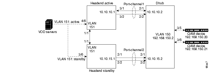
Figure 4-4 illustrates where HSRP is used with UDLR (unidirectional link routing).
Note
http://www.cisco.com/univercd/cc/td/doc/product/software/ios122/122cgcr/fipr_c/ipcpt3/1cfudlr.htm
For UDLR command syntax, refer to Unidirectional Link Routing Commands at the following URL:
http://www.cisco.com/univercd/cc/td/doc/product/software/ios122/122sup/122csum/csum1/122csip3/
1sfudlr.htmFigure 4-4 Switch in Dhub: HSRP with UDLR
Scenario Characteristics
Note the following key characteristics of this scenario:
•
–
–
•
–
–
–
•
Failure Recovery Time
Time to recover from a link outage is 5-7 seconds.
Configuration Examples
For sample configurations for this scenario, see HSRP with UDLR.
Switch in Dhub: HSRP with Interface Tracking
Figure 4-5 illustrates HSRP between the headend and Dhub switches, with the HSRP interface tracking feature applied.
Figure 4-5 Switch in Dhub: HSRP with Interface Tracking
Scenario Characteristics
Note the following key characteristics of this scenario:
•
•
•
•
•
Failure Recovery Time
If Port-channel1 fails, recovery time is 1-2 seconds.
Configuration Examples
For sample configurations for this scenario, see HSRP with Interface Tracking.
Layer 3 1+1 Protection
Layer 3 1+1 protection covers four of the five failure scenarios, but is less costly than headend switch protection. Failure scenarios 1 through 4 are covered, but the failure of a headend switch itself is not covered.
This protection mechanism is identical to headend switch protection, except that it has a single headend switch. Because of this, the redundant interfaces connecting the headend and Dhub switches are both connected to the same headend switch.
Figure 4-6 Switch in Dhub: Layer 3 1+1 Protection
The configuration of the headend and Dhub switches, and the network operation for each scenario, are identical to that in Headend Switch Protection, except that HSRP redundancy is not enabled (or needed) on the single headend switch.
Table 4-3 summarizes the protections available, with failover times, for switch-in-Dhub failure scenarios.
Layer 3 1+1 Protection Scheme
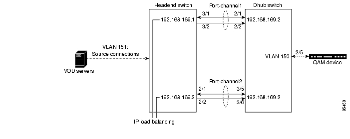
This section illustrates an example Layer 3 1+1 protection scheme for use in switch-in-Dhub scenarios. Figure 4-7 illustrates the optical topology for the specific case of two Cisco Catalyst 4507 switches (running Supervisor Engine IV) with WS-4306 interface cards and transmit and receive GBICS. Figure 4-8 illustrates the IP topology for the above.
Figure 4-7 Switch in Dhub: Layer 3 1+1 Protection—Optical Topology
Figure 4-8 Switch in Dhub: Layer 1 1+1 Protection—IP Topology
Scenario Characteristics
Note the following key characteristics of this scenario:
•
•
Failure Recovery Time
In the event of a link failure, recovery time is 5-7 seconds.
Configuration Examples
For sample configurations for this scenario, see Layer 3 1+1 Protection.
No Switch in Dhub
There are two redundancy options for the no-switch-in-Dhub topology:
These are discussed in detail below.
Note
Y-cable Optical Protection
Y-cable optical protection uses an optical splitter in the Dhub to send the same optical signal through a redundant DWDM network to two GE interfaces at the QAM module. To support this method of protection, the QAM must support optical failover between the two interfaces. (See Gigabit Ethernet QAM Devices.)
Because this failover method duplicates all of the components of the DWDM network, it protects against any failure in the network. The failover time depends on how quickly the QAMs can detect LOS (loss of signal) on the primary GE port and switch to the backup GE port as a result. The detection of LOS on a standard GE port is typically on the order of 5 msec.
Figure 4-9 No Switch in Dhub: Y-cable Optical Protection
Fiber Splitter Redundancy
Fiber splitter redundancy works identically to Y-cable redundancy, except that it splits the optical signal after the DWDM multiplexer at the headend. Since the signal is split after the DWDM multiplexer, only one DWDM multiplexer is needed at the headend. This redundancy scheme trades off the ability to deal with failures in optical components at the headend for the savings of not having to duplicate optical components in the headend.
This method relies on the same optical failover mechanism in the QAMs that Y-cable redundancy uses. As a result, the recovery times will be the same for these two protection schemes.
Table 4-4 summarizes the protections available, with failover times, for no-switch-in-Dhub failure scenarios.
![]()
![]()
![]()
![]()
![]()
![]()
![]()
![]()
Posted: Mon Mar 13 11:14:10 PST 2006
All contents are Copyright © 1992--2006 Cisco Systems, Inc. All rights reserved.
Important Notices and Privacy Statement.