|
|

Table Of Contents
Implementing and Configuring the Solution
Configuring the Headend: Cisco Catalyst Switches (Basic Configuration)
Configuring the Dhub: Cisco Catalyst Switches
Establishing Multiple EtherChannels
Implementing the Cisco ONS 15216 FlexLayer
Implementing the Cisco 15216 OSC-1510
Implementing the Cisco uMG9820 QAM Gateway
Implementing and Configuring the Solution
Overview
This chapter addresses the two fundamental Ethernet/IP architectures:
In addition, resources for implementing the optical architecture are provided below:
•
Implementing the Cisco uMG9820 QAM Gateway
Switch in the Dhub
This section addresses the following topics:
•
•
•
•
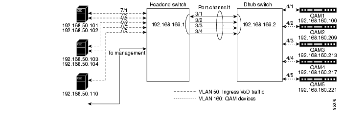
For background, see Switch in the Dhub. Figure 3-1 illustrates an example network architecture for the switch-in-Dhub scenario. Extrapolate to add additional servers and switches.
Figure 3-1 Example Network Architecture: Switch in Dhub
Configuring the Headend: Cisco Catalyst Switches (Basic Configuration)
This section illustrates the nondefault provisioning that is required to establish payload channels between a Cisco Catalyst switch and the VoD servers and QAMs where a switch is used in the Dhub. Switch defaults are not discussed here, but are available in "Switch in Dhub: Sample Configurations for Cisco Catalyst 4500 Series Switches."
Note
http://www.cisco.com/univercd/cc/td/doc/product/lan/cat4000/index.htmThe following topics are illustrated:
•
•
•
Establishing Quality of Service (QoS)
For background, see QoS. Cisco recommends that you tag all video traffic so that it is queued properly and efficiently. The following procedure illustrates the key interrelated components of establishing QoS for video.
Step 1
qosStep 2
class-map match-all class_videomatch access-group name acl_videoThe extended access-list name acl_video is arbitrary. The option match-all ensures that all statements in the list are matched.
Step 3
ip access-list extended acl_videoremark Identify video traffic (UDP ports 257-33023).permit udp any any range 257 33023Above port 256, ranges will vary, depending upon the installation.
Note
Step 4
policy-map setDSCP <---This value is arbitrary, and is applied to service-policy on a VLANdescription Mark all video traffic with DSCP of EFclass class_videoset ip dscp 46The parameter setDSCP is arbitrary, and provides an association set by the service-policy command, in the VLAN(s) for video traffic. The value 46 turns on the EF (Expedited Forwarding) flag.
The following helps explain the DSCP values and Tx-Queue (transmit queue) mappings, and illustrates how policy-map changes the ToS bits for all incoming packets that are in class_video. The DSCP bits are the first 6 bits, and the last two (the ECT and CE bits) are ignored.
The incoming video packets from the VoD servers have a DSCP of 7, mapped from hex to binary as follows:
!! Type of service = 1C! 0 0 0 . . . . . = routine! . . . 1 . . . . = low delay! . . . . 1 . . . = high throughput! . . . . . 1 . . = high reliability! . . . . . . 0 . = ECT bit - transport protocol will ignore the CE bit! . . . . . . . 0 = CE bit - no congestion!The following policy-map changes the DSCP to 46.
!! Type of service = B8! 1 0 1 . . . . . = Critic/ECP! . . . 1 . . . . = low delay! . . . . 1 . . . = high throughput! . . . . . 0 . . = normal reliability! . . . . . . 0 . = ECT bit - transport protocol will ignore the CE bit! . . . . . . . 0 = CE bit - no congestion!Here is the default DSCP mapping. The policy-map changes the video packets from the DSCP value of 7, which maps to Tx-Queue 1, to a DSCP value of 46, which maps to Tx-Queue 3. Use the command show qos maps to view the mapping table and confirm this:
! Headend#show qos maps! DSCP-TxQueue Mapping Table (dscp = d1d2)! d1 : d2 0 1 2 3 4 5 6 7 8 9! -------------------------------------! 0 : 01 01 01 01 01 01 01 01 01 01! 1 : 01 01 01 01 01 01 02 02 02 02! 2 : 02 02 02 02 02 02 02 02 02 02! 3 : 02 02 03 03 03 03 03 03 03 03! 4 : 03 03 03 03 03 03 03 03 04 04! 5 : 04 04 04 04 04 04 04 04 04 04! 6 : 04 04 04 04Enabling OSPF
Enable OSPF, as in the following example.
router ospf 100log-adjacency-changespassive-interface Vlan50network 1.1.1.0 0.0.0.255 area 0network 192.168.0.0 0.0.255.255 area 0distribute-list 1 in Port-channel1distribute-list 2 in Port-channel2distribute-list 3 in Port-channel3distribute-list 4 in Port-channel4distribute-list 4 in Port-channel5OSPF will advertise all the headend switch interfaces to the DHubs. This includes the GRE tunnel endpoints (loopbacks) and the VoD server VLAN. The distribute-list commands are used to block alternative routes to DHub QAM VLANs from being added to the routing table. In other words, the only path to VLAN160 on DHub A should be through Port-channel1.
Area 0, the default, represents a backbone.
Enabling Load Balancing
Both Layer 3 and EtherChannel load balancing should be used on the headend switch. Default hashing algorithms XOR the source and destination IP addresses. In the VoD application, this produces a small set to be distributed across multiple equal-cost paths. To increase this set and achieve a better distribution, Cisco recommends that you include the Layer 4 destination ports in the hashing algorithm.
Layer 3 Load Balancing
For Layer 3 (CEF IP) load balancing, the Layer 4 ports are included with the following command:
ip cef load-sharing algorithm include-ports destinationEtherChannel Load Balancing
For EtherChannel load balancing, the Layer 4 ports are used with the following command:
port-channel load-balance dst-port
Note
Establishing Interfaces on the Headend Switch
Traffic is segregated naturally through the assignment of interfaces. Corresponding interfaces must also be configured on any Dhubs in the switch-in-Dhub scenario. Interfaces are assigned to VLANs on the switch.
The following interface-related topics are illustrated, in the general order in which they would be applied:
•
•
•
•
•
•
Establishing a VLAN and Addresses for VoD Server Traffic to the Switch
The following illustrates the establishment of a VLAN and range of IP addresses for video traffic to the switch. (See Figure 3-1.) Addressing will vary for multiple servers in disparate networks.
Step 1
interface Vlan50description VoD Serversip address 192.168.50.2 255.255.255.0no ip redirectsno ip unreachables
Note
Step 2
service-policy input setDSCP <---Applies values set by policy-mapStep 3
standby 50 ip 192.168.50.1 <---See Note below
Note
Be sure to include a group number on this and all standby commands. Otherwise, the group number defaults to 0, resulting in improper operation.Establishing the GE Interfaces to the VoD Servers
Refer to Figure 3-1. The following establishes GE interfaces for the video traffic to the VoD servers, interfaces GigabitEthernet7/1, GigabitEthernet7/5, GigabitEthernet7/9, GigabitEthernet7/13, and GigabitEthernet7/17, assigning them to VLAN 50.
Note
Caution
interface GigabitEthernet7/1description VODserver1 GigE0switchport access vlan 50switchport mode accessload-interval 30duplex fullspeed 1000 <---See Note above!interface GigabitEthernet7/5description VODserver1 GigE1switchport access vlan 50load-interval 30speed 1000!interface GigabitEthernet7/9description VODserver2 GigE0switchport access vlan 50load-interval 30speed 1000!interface GigabitEthernet7/13description VODserver2 GigE1switchport access vlan 50load-interval 30speed 1000!interface GigabitEthernet7/17description VODserver3 GigE0switchport access vlan 50load-interval 30speed 1000Establishing GE Interfaces from the Headend Switch to the Dhub Switch
Refer to Figure 3-1. The following illustrates the establishment of interfaces GigabitEthernet3/1, GigabitEthernet3/2, GigabitEthernet3/3, and GigabitEthernet3/4. GigabitEthernet3/1 is bidirectional, with all others being unidirectional. Corresponding channels will need to be established on the Dhub switch. Once you establish the interfaces, assign them to an EtherChannel as described in Establishing an Asymmetric EtherChannel to the Dhub Switch.
Caution
interface GigabitEthernet3/1description Bidirectional Link of EtherChannelno switchportno ip addressload-interval 30tx-queue 3 <---See first Note belowpriority highchannel-group 1 mode on <---See second Note below!
Note
Note
interface GigabitEthernet3/2description Unidirectional Link of EtherChannelno switchportno ip addressload-interval 30tx-queue 3priority highunidirectional send-only <---See Note belowchannel-group 1 mode on!
Note
interface GigabitEthernet3/3description Unidirectional Link of EtherChannelno switchportno ip addressload-interval 30tx-queue 3priority highunidirectional send-onlychannel-group 1 mode on!interface GigabitEthernet3/4description Unidirectional Link of EtherChannelno switchportno ip addressload-interval 30tx-queue 3priority highunidirectional send-onlychannel-group 1 mode onFor the corresponding configuration on the Dhub switch, see Establishing GE Interfaces from the Dhub Switch to the Headend Switch.
Establishing an Asymmetric EtherChannel to the Dhub Switch
Once the GE interfaces are configured, they can be assigned to an EtherChannel. The switch-in-Dhub scenario requires the establishment of an asymmetric EtherChannel between the switches, as illustrated below. Refer to Figure 3-1.
interface Port-channel1description asymmetric EtherChannel to DHub_Aip address 192.168.169.1 255.255.255.252load-interval 30The load-interval is the measurement interval for interface statistics. (The default load-interval is 300.)
For the corresponding configuration on the Dhub switch, see Establishing an Asymmetric EtherChannel from the Dhub Switch to the Headend Switch.
Establishing Tunnels to a Dhub Switch (Optional)
As noted in Ethernet Topology, with this UDLR application tunnels provide the mechanism for creating a return path for a unidirectional interface or EtherChannel. Create loopback interfaces on the headend and Dhub switches to serve as endpoints for the UDLR tunnel. Loopback interfaces (rather than physical interfaces) are used as endpoints of the tunnel, because loopback interfaces never go down, and each tunnel requires it own unique set of endpoints. In this example, the return path for a unidirectional EtherChannel (Port-channel2) will be configured, beginning at the headend switch. For the corresponding configuration on the Dhub switch, see Establishing Tunnels to a Headend Switch (Optional).
Tunnels are used in the following scenarios:
•
•
To establish a tunnel from the headend switch to a Dhub switch:
Step 1
interface Loopback2description Endpoint of Tunnel2ip address 1.1.1.5 255.255.255.255You must create a corresponding destination address to communicate to the same loopback on the Dhub switch, as shown in Step 2.
Tip
Step 2
interface Tunnel2description Return Path for Unidirectional EtherChannel to DHub_Bno ip addresstunnel source 1.1.1.5tunnel destination 2.2.2.6tunnel udlr receive-only Port-channel2You also must create Tunnel2 on the Dhub switch. See Establishing Tunnels to a Headend Switch (Optional).
Note
Step 3
Step 4
router ospf 100 network 1.1.1.0 0.0.0.255 area 0
Note
Establishing Interfaces for Management (Optional)
If your installation supports a management application, simply assign Layer 3 addresses to dedicated northbound and southbound management channels.
Using and Monitoring HSRP
If redundant switches are used, it is important to monitor the status of the failover protocol. You should also use this command to determine the virtual MAC address that should be configured on VoD servers that do not support ARP.
Note
The following example illustrates the result of a show standby command:
Headend#show standbyVlan50 - Group 50Local state is Active, priority 100Hellotime 3 sec, holdtime 10 secNext hello sent in 0.346Virtual IP address is 192.168.50.1 configuredActive router is localStandby router is unknownVirtual mac address is 0000.0c07.ac322 state changes, last state change 3d22hIP redundancy name is "hsrp-Vl50-50" (default)Example Configuration on a Headend Switch
For a complete example configuration of a headend switch connected to a single Dhub switch over a single EtherChannel, see Single EtherChannel: Headend Switch to Dhub Switch.
Configuring the Dhub: Cisco Catalyst Switches
In the switch-in-Dhub architecture, the configuration on the Dhub switch is considerably simpler. Simply maintain the correspondences and VLANs that were established at the headend. This section addresses the following topics:
•
•
Establishing QoS
No configuration is required on Dhub switches to perform QoS. For issues that pertain to the headend switch, see QoS.
Enabling OSPF
Cisco recommends that you enable OSPF routing on the switch, to advertise to the headend switch the route to the QAM VLAN, as well as to receive routes from the headend switch. Here we set the PID to 100, the same as in Enabling OSPF.
router ospf 100log-adjacency-changespassive-interface Vlan160 <---See Note belownetwork 192.168.0.0 0.0.255.255 area 0
Note
Enabling Load Balancing
No configuration is required on the Dhub switch to perform load balancing. For issues that pertain the to the headend switch, see Load-Balancing Strategies.
Establishing Interfaces on the Dhub Switch
The interfaces established on the Dhub switch must naturally correspond to those on the headend switch. Below we illustrate the following:
•
•
•
Establishing a VLAN and Addresses for Video Traffic to the QAM Devices
The following illustrates the establishment of a VLAN and range of IP addresses for video traffic to the QAM devices. Refer to Figure 3-1.
interface Vlan160description QAM Devicesip address 192.168.160.1 255.255.255.0no ip redirectsno ip unreachables
Note
Establishing GE Interfaces from the Dhub Switch to the Headend Switch
Below we establish Gigabit Ethernet interfaces GigabitEthernet3/1, GigabitEthernet3/2, GigabitEthernet3/3, and GigabitEthernet3/4. Interface GigabitEthernet3/1 is bidirectional, with all others being unidirectional. (Refer to Figure 3-1.) This corresponds to Establishing GE Interfaces from the Headend Switch to the Dhub Switch. Once you establish the interfaces, assign them to an EtherChannel as described in Establishing an Asymmetric EtherChannel from the Dhub Switch to the Headend Switch.
interface GigabitEthernet3/1description Bidirectional Link of EtherChannelno switchportno ip addressload-interval 30channel-group 1 mode on!interface GigabitEthernet3/2description Unidirectional Link of EtherChannelno switchportno ip addressload-interval 30unidirectional receive-onlychannel-group 1 mode on!interface GigabitEthernet3/3description Unidirectional Link of EtherChannelno switchportno ip addressload-interval 30unidirectional receive-onlychannel-group 1 mode on!interface GigabitEthernet3/4description Unidirectional Link of EtherChannelno switchportno ip addressload-interval 30unidirectional receive-onlychannel-group 1 mode onEstablishing an Asymmetric EtherChannel from the Dhub Switch to the Headend Switch
Once GE interfaces have been configured, they can be aggregated in an EtherChannel. The switch interface used is the same as that on the headend switch. (Refer to Figure 3-1.) This corresponds to Establishing an Asymmetric EtherChannel to the Dhub Switch.
Note
See Establishing an Asymmetric EtherChannel to the Dhub Switch.
interface Port-channel1description asymmetric EtherChannel from Headendip address 192.168.169.2 255.255.255.252load-interval 30The load-interval is the measurement interval for interface statistics. The default load-interval is 300.
Establishing Tunnels to a Headend Switch (Optional)
See Establishing Tunnels to a Dhub Switch (Optional). This configuration on the Dhub switch must correspond to that established on the headend switch.
To establish a tunnel from the Dhub switch to the headend switch:
Step 1
interface Loopback2description Endpoint of Tunnel2ip address 2.2.2.6 255.255.255.255A corresponding destination address, as illustrated below, will need to be created for communicating to the same loopback on the headend switch.
Step 2
interface Tunnel2description Return Path for Unidirectional EtherChannel to Dhub_Bno ip addresstunnel source 2.2.2.6tunnel destination 1.1.1.5tunnel udlr send-only Port-channel2tunnel udlr address-resolutionThis corresponds to Tunnel2 on the headend switch.
Note
Step 3
Manually Configuring the ARP and MAC Address Tables on the Dhub Switch (Optional)
Where the tables must be populated manually, the following lines illustrate the correspondence that will have to be entered, through a text editor, into the configuration file. (See Manual Population of ARP and Bridging Tables on the Dhub Switch.) The addresses of the QAM devices being supported are shown in Figure 3-1.
ARP Example
The following lines will find their MAC address correspondence in MAC Address Table Example, below:
arp 192.168.160.100 0020.a300.92aa ARPAarp 192.168.160.209 000b.4627.0001 ARPAarp 192.168.160.213 000b.4627.0002 ARPAarp 192.168.160.217 000b.4627.0003 ARPAarp 192.168.160.221 000b.4627.0004 ARPAMAC Address Table Example
The following lines correspond to the ARP lines in ARP Example, above:
mac-address-table static 0020.a300.92aa vlan 160 interface GigabitEthernet4/1mac-address-table static 000b.4627.0001 vlan 160 interface GigabitEthernet4/2mac-address-table static 000b.4627.0002 vlan 160 interface GigabitEthernet4/3mac-address-table static 000b.4627.0003 vlan 160 interface GigabitEthernet4/4mac-address-table static 000b.4627.0004 vlan 160 interface GigabitEthernet4/5Connecting to QAM Devices
The following example illustrates the assigning of interfaces in the Dhub switch to the QAM devices, in a single VLAN.
interface GigabitEthernet4/1description QAM1switchport access vlan 160switchport mode accessload-interval 30speed nonegotiate!interface GigabitEthernet4/2description QAM2switchport access vlan 160switchport mode accessload-interval 30!interface GigabitEthernet4/3description QAM3switchport access vlan 160switchport mode accessload-interval 30Example Configuration on Dhub Switch
For a complete example configuration of a Dhub switch connected to a single headend switch over a single EtherChannel, see Single EtherChannel: Dhub Switch to Headend Switch.
Establishing Multiple EtherChannels
When more than one EtherChannel interface is used between a headend and a Dhub switch, one EtherChannel will need to be asymmetric, to support bidirectional control traffic. The return path for the second EtherChannel uses UDLR over the bidirectional path on the asymmetric EtherChannel, and is established as discussed in Establishing Tunnels to a Dhub Switch (Optional). See Figure 3-2. See also Load-Balancing Strategies.
Figure 3-2 Switch in Dhub: Multiple EtherChannels
Configuration is as in Configuring the Headend: Cisco Catalyst Switches (Basic Configuration), and Configuring the Dhub: Cisco Catalyst Switches, but with the following differences:
•
–
–
–
•
–
–
–
For example configurations of the headend and Dhub switch, see the following:
•
•
Establishing Subtended Dhubs
With subtended Dhubs (see Subtended Dhubs), a unidirectional EtherChannel from one Dhub switch is returned through another Dhub switch. See Figure 3-3.
Figure 3-3 Switch in Dhub: Subtended Control Path
Configuration is as in Configuring the Headend: Cisco Catalyst Switches (Basic Configuration), and Configuring the Dhub: Cisco Catalyst Switches, but with the following differences:
•
–
–
–
•
–
–
–
–
For example configurations of the headend and Dhub switch, see the following:
•
•
•
No Switch in the Dhub
For background, see No Switch in the Dhub. This section addresses the following topics:
For sample configurations that illustrate the above, see "No Switch in Dhub: Sample Configurations for Cisco Catalyst 4500 Series Switches."
Note
Establishing a Single VLAN
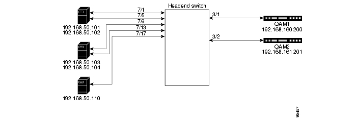
Figure 3-4 illustrates the implementation of a single VLAN, the simplest case. Here all ports are members of the same VLAN. For a sample switch configuration, see Single VLAN.
Figure 3-4 No Switch in Dhub: Single VLAN
Establishing a Split VLAN
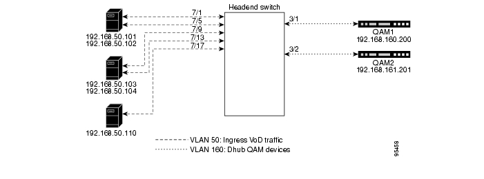
Figure 3-5 illustrates the implementation of a split VLAN, where one VLAN is reserved for ingress VoD traffic (source ports) and another for the QAM devices (destination ports). For a sample switch configuration, see Split VLAN.
Figure 3-5 No Switch in Dhub: Split VLAN
Establishing Multiple VLANs
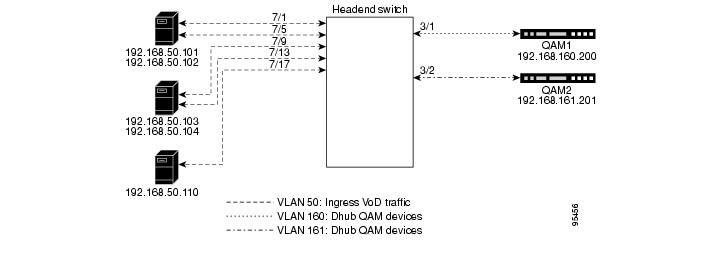
Figure 3-6 illustrates the implementation of a VLAN for ingress VoD traffic as well as multiple VLANs to the QAM devices. Here, source ports are members of one VLAN, and destination ports are grouped (usually by region) into discrete VLANs. For a sample switch configuration, see Multiple VLANs.
Figure 3-6 No Switch in Dhub: Multiple VLANs
Implementing Optics
The following discussions present a variety of options for implementing the various optics and supervisory channels for the Cisco Gigabit-Ethernet Optimized VoD Solution:
•
•
Implementing the Cisco ONS 15216 FlexLayer
The Cisco Gigabit-Ethernet Optimized VoD Solution uses the Cisco ONS 15216 FlexLayer solution to provide modular support for a variety of optical functions. A single chassis accommodates multiplex/demultiplex filters, combiner or splitter assemblies, and optical attenuators, providing for easy and cost-effective expansion.
Note
http://www.cisco.com/warp/public/cc/pd/olpl/metro/15200/prodlit/flexp_ds.htm
To install and use the Cisco ONS 15216 FlexLayer and its various components, refer to Cisco ONS 15216 FlexLayer User Guide, Release 1.0, at the following URL:
http://www.cisco.com/univercd/cc/td/doc/product/ong/15216/flxlyr10/Implementing the Cisco 15216 OSC-1510
The Cisco ONS 15216 OSC-1510 can be used in the Cisco Cisco Gigabit-Ethernet Optimized VoD Solution to provide optical supervisory channel (OSC) communication to a site without the need for a OADM (optical add/drop multiplexer), EDFA (erbium-doped fiber amplifier), or multiplexing/demultiplexing at that site. This passive single-channel 100-GHz device allows you to add or drop a protected OSC wavelength in each direction at any point of a DWDM link. The dropped OSC channel is then sent to the receive GBIC port on the switch.
Note
http://www.cisco.com/univercd/cc/td/doc/product/ong/15216/osc.htm
Although that document refers to the Cisco Catalyst 2950 switch, the Cisco ONS 15216 OSC-1510 is compatible with the Cisco Catalyst 4500 series switches.
Implementing the Cisco uMG9820 QAM Gateway
For information on preparing, installing, starting, and configuring the Cisco uMG9820 QAM Gateway, refer to the Cisco uMG9820 QAM Gateway Installation and Configuration Guide, at the following URL:
http://www.cisco.com/univercd/cc/td/doc/product/cable/vod/umg9820/index.htm
![]()
![]()
![]()
![]()
![]()
![]()
![]()
![]()
Posted: Mon Mar 13 10:53:01 PST 2006
All contents are Copyright © 1992--2006 Cisco Systems, Inc. All rights reserved.
Important Notices and Privacy Statement.