|
|

Table Of Contents
Deploying the Cisco Gigabit-Ethernet Optimized VoD Solution in Fiber Ring Topologies
Ring-Based Transport vs. Gigabit Ethernet
Converting Fiber Rings to Hub-and-Spoke Gigabit Ethernet
Deploying the Cisco Gigabit-Ethernet Optimized VoD Solution in Fiber Ring Topologies
This chapter describes how the hub-and-spoke architecture of the Cisco Gigabit-Ethernet Optimized VoD Solution fits into networks where existing fiber has already been deployed in ring topologies. Fiber rings are very common in MSOs (multiple system operators) that have historically used SONET for video transport and now want to upgrade their transport infrastructure using the same fiber rings.
A hub-and-spoke model based on Gigabit Ethernet (GE) cannot be used in a fiber-ring topology unless the fiber ring is converted into a logical hub-and-spoke topology at the optical layer. Because of the additional optical complexity of using GE, it may seem simpler and more cost-effective to deploy a ring-based packet switching technology such as DPT (Dynamic Packet Transport) directly on the fiber ring.
The information presented in this chapter addresses only the use of physical dark-fiber media and xWDM methods.
Note
For more information about DPT, refer to Dynamic Packet Transport at the following URL:
http://www.cisco.com/warp/public/cc/techno/wnty/dpty/index.shtmlThis chapter presents the following major topics:
•
Discusses the benefits and drawbacks of ring-based packet-switching technologies such as DPT compared to GE in VoD and video broadcast networks.
•
Describes the basic principles behind converting a fiber ring into a logical hub-and-spoke topology at the optical layer.
Note
Ring-Based Transport vs. Gigabit Ethernet
It is straightforward to deploy ring-based packet-transport technologies such as DPT in dual fiber-ring topologies, because the DPT interfaces can be used to drive dark fiber directly. As noted previously, with GE the fiber ring must be converted into a logical hub-and-spoke topology at the optical layer. This is an advantage for ring-based packet-transport technologies over GE, because less passive and active optical equipment needs to be deployed.
In the event of a fiber cut, the DPT network layer also has the ability to reroute traffic on the ring in less than 50 msec. Since the Cisco Gigabit-Ethernet Optimized VoD Solution uses Gigabit EtherChannel, the network-layer convergence times in the event of a fiber cut are similar to those of DPT. An EtherChannel interface is capable of detecting a fiber cut and re-load-balancing the traffic on the remaining members of an EtherChannel group in less than 10 msec. Consequently, both DPT and GE have similar network-layer convergence times in the event of a fiber cut.
Switching Efficiency
Ring-based packet transport technologies also be compared to Gigabit Ethernet by comparing the relative switching efficiency of each technology using different traffic patterns. The switching efficiency for a particular traffic pattern in a transport network can be expressed in terms of the ratio of the traffic entering or exiting the network to the total switching capacity of the network. To determine the relative cost of a particular transport technology with a given traffic pattern (assuming the cost to switch a unit of bandwidth in a particular switching technology is linear), the switching efficiency can be multiplied by the cost to switch a unit of bandwidth in a given transport technology. The analysis used in this section assumes that the cost to switch a unit of bandwidth in ring-based packet transport technologies is the same as that for Gigabit Ethernet. Given this assumption, the relative switching cost can be determined by using the relative switching efficiency of each technology used for video distribution.
Ring-Based Packet-Transport Technologies
Ring-based packet-transport technologies are most bandwidth-efficient when traffic distribution around the ring is even. Traffic distribution around a ring will be most even when the distribution pattern of traffic entering and leaving the ring at each ring node is random. When traffic is distributed evenly around a ring, each switching node around the ring (the DPT interfaces) will be switching the same amount of traffic on the ring, off the ring, and around the ring. Since the switching capacity of each node in ring-based packet-transport technologies such as DPT must be the same, a random traffic distribution pattern is the best in terms of switching efficiency. The switching efficiency of a ring network that uses a random traffic-distribution pattern is approximately 1.
The most inefficient traffic-distribution pattern for ring-based packet-transport technologies occurs when all traffic originates or terminates at one node on the ring. Unfortunately, the traffic in typical video distribution systems originates from a single network node—the headend. Consequently, the traffic pattern associated with video distribution matches this model.
With a video-distribution traffic pattern, the headend node will be switching all traffic onto the ring. This traffic will then be switched off the ring by one of the other nodes (that is, a Dhub). Because the switching capacity of each node must be the same for packet transport technologies such as DPT, this traffic-distribution pattern uses switch resources inefficiently. If the number of nodes is expressed by the variable N, the switching efficiency E of a ring network for video distribution can be expressed (in a common spreadsheet or C-based routine) by Eq. (1):
Eq. (1) E = (N - 1) / (Roundup((N - 1) / 2, 1) * N)
where Roundup() is Roundup(number, num_digits). Taking the value of the first parameter to the value of the second parameter (the value to round up to), this rounds a number upwards (away from zero).
Eq. (1) shows that as the number of nodes in a ring network used for video distribution goes up, the switching efficiency of the network goes down. For video distribution, a ring network with three nodes on the ring is 66% efficient, while a ring network with five nodes on the ring is only 40% efficient. Note that Eq. (1) takes into account the fact that ring networks such as DPT networks are built to transport bidirectional traffic, and so have equal switching capacity in both directions around the ring.
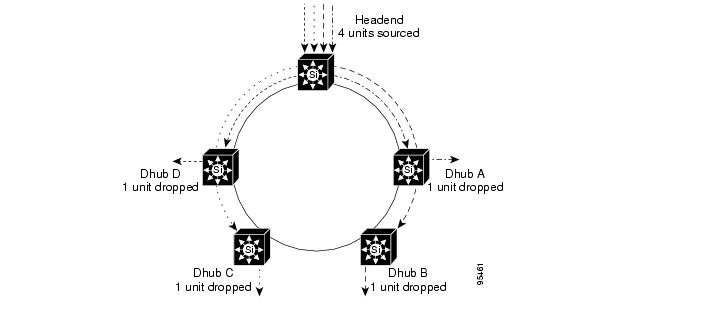
Figure 6-1 illustrates how traffic flows, with the resulting switching efficiency, when a DPT ring is used for video distribution. Here the ring must be provisioned to carry two units of bandwidth in each direction, or four units of switching capacity per node. This is because the headend switch will switch two units of bandwidth in both directions. Because there are five nodes in the ring, the total switching capacity of the ring is 4*5 or 20 units of bandwidth. The amount of traffic that enters or leaves the network can be determined by whether traffic is sourced or dropped at each node on the ring. This amounts to eight units of bandwidth in our example. Therefore, the switching efficiency E of a five-node network used for video distribution is 8/20 = 40%.
Figure 6-1 Switching Efficiency for a Five-Node Video Distribution Ring
Note that the switching efficiency of a ring-based packet-transport network used for video distribution may change, depending on the distribution of traffic from the headend to the Dhubs. When the traffic from the headend is evenly split in both directions, the ring must be provisioned for the worst-case amount of traffic originating from the headend. A totally uneven traffic distribution can result in all traffic from the headend flowing in one direction only. Eq. (1) made the assumption that the amount of traffic sent from the headend to each Dhub is the same. Removing this assumption, Eq. (2) shows the worst-case switching efficiency E for N nodes in a ring-based packet-network for video:
Eq. (2) E = 1 / (N - 1)
Gigabit Ethernet
When Gigabit Ethernet is deployed in a hub-and-spoke topology, it is most efficient when all traffic originates or terminates at the hub source. This matches the traffic pattern for video distribution, and is the reason why hub-and-spoke GE is well-suited for video distribution—although the switching efficiency for the network will still be less than 1.
As shown in Eq. (3), switching efficiency E in a single-tier hub-and-spoke GE network can be determined by taking the ratio of the bandwidth sourced at the headend, BH, to the sum of the bandwidths BDn that are provisioned between the headend and each Dhub:
Eq. (3) E = BH / (BD1 + BD2 + BD3 + ... BDn)
The bandwidth provisioned at the headend and on each Dhub link will be determined by the MSO, and is typically based on a probability model that takes into account the following:
•
•
Both Zipf and binomial distributions have been used to model the tuning behavior of customers. A general law of probability states that as the size of a sample population increases, the ratio of peak usage to average usage within that population decreases. This is illustrated below.
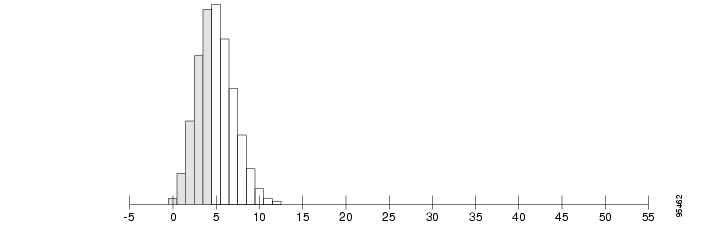
Figure 6-2 shows a binomial distribution with an average probability of 10% and a population size of 50. Here the ratio of the maximum (12.5) to the average (5) for a population of 50 subscribers is approximately 2.5.
Figure 6-2 Binomial Probability Distribution for a Population Sample of 50
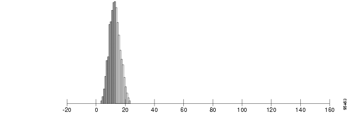
Figure 6-3 shows that the ratio of the maximum (25) to the average (15) for a population of 150 subscribers is approximately 1.66.
Figure 6-3 Binomial Probability Distribution for a Population Sample of 150
When MSOs provision VoD bandwidth in a headend, they apply this probability analysis to a subscriber population that is the sum of all subscribers in all Dhubs connected to the headend. To provision the bandwidth for each Dhub link, they will use the probability analysis described above on the subscriber population of that Dhub.
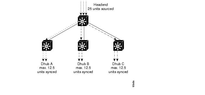
If analysis results of the above examples were used for a headend serving three Dhubs of 50 subscribers each, then the bandwidth that would be provisioned on each of the Dhub links from Figure 6-2 would be 12.5 units, while the amount of bandwidth that would be provisioned in the headend from Figure 6-3 would be 25 units. Using Eq. (3), the switching efficiency of this network would be 25 / (12.5 + 12.5 + 12.5) = 66%. Figure 6-4 illustrates the traffic flows and resulting provisioning numbers that result from this analysis.
Figure 6-4 Hub-and-Spoke Efficiency Model
Note that as the population of subscribers using a hub-and-spoke model increases, the bandwidth efficiency of the network will increase. This is because of the nature of binomial distributions. As the sample size of a binomial distribution increases, the ratio of average to peak with that distribution decreases.
Converting Fiber Rings to Hub-and-Spoke Gigabit Ethernet
In order to run hub-and-spoke Gigabit Ethernet in an environment where existing fiber is already deployed in rings, the fiber ring must be converted to a logical hub-and-spoke network by means of optical splitters and combiners and DWDM filters. This section provides an example of how to provide optical hub-and-spoke connectivity over a physical fiber laid out in a ring.
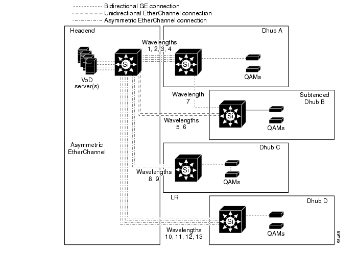
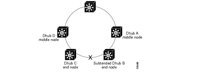
Figure 6-5 shows an example Cisco Gigabit-Ethernet Optimized VoD Solution (Release 1.0 and Release 1.1) GE topology that can be built over a fiber ring. Figure 6-6 shows an example mapping of the headend and Dhub switches shown in Figure 6-5 to nodes on a physical fiber ring. Fiber rings typically consist of two or more fibers. This section shows how to convert one fiber into the downstream hub-and-spoke optical path.
Figure 6-5 Cisco Gigabit-Ethernet Optimized VoD Solution (Release 1.0 and Release 1.1)
Gigabit Ethernet Topology
Figure 6-6 Cisco Gigabit-Ethernet Optimized VoD Solution 1.0 Fiber Topology
To convert the fiber topology shown above to a logical hub-and-spoke topology, the ring must first be broken at a point that is topologically farthest from the headend switch: that location is the fiber that connects Dhub B to Dhub C. Once this fiber is broken, the nodes on the ring can be labeled in relation to their position on the ring. Nodes that have a fiber going in and coming out are labeled middle nodes, while the two nodes that are adjacent to the broken fiber are labeled end nodes. The optical configuration for a middle node is slightly different from that for an end node, because a middle node splits the optical signal in order to pass it to downstream nodes.
Once the nodes are labeled, an optical wavelength plan must be drawn based on the Ethernet topology. Figure 6-5 labels each group of GE links with a set of DWDM wavelengths that will be used to carry the optical signals from the DWDM GBICs in the headend to the Dhubs. With the wavelength plan in place, the optical designs for each node can be created.
Note
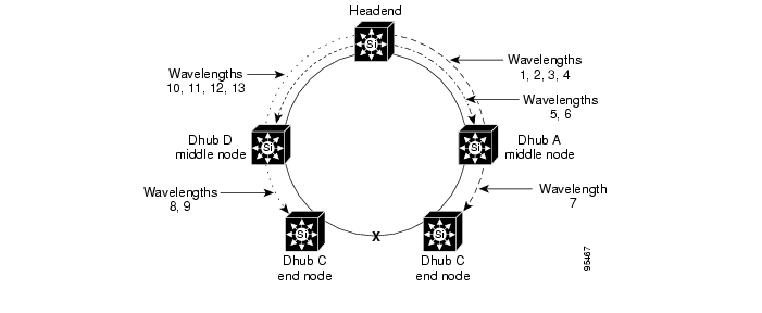
Figure 6-7 shows how the wavelength plan from Figure 6-5 maps to the fiber topology.
Figure 6-7 Converting a Fiber Ring to Hub-and-Spoke Topology
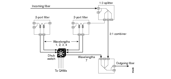
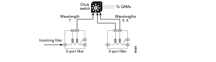
Figure 6-8 shows the optical design for Dhub A. Because Dhub A is a middle node, an optical splitter must be used to split the optical signal into one fiber for the Dhub switch and another fiber that feeds downstream nodes. From Figure 6-5, the switch in Dhub A terminates four GE links, which are carried in DWDM wavelengths 1, 2, 3, and 4. These wavelengths are filtered out of the fiber from the splitter by means of two 2-port filters. The switch in Dhub A has an outgoing GE link that feeds subtended Dhub B over wavelength 7. That link is fed to the outgoing fiber by means of an optical combiner.
Figure 6-8 Middle Node Details: Dhub A
Figure 6-9 shows the optical design for subtended Dhub B. Since Dhub B is an end node, no optical splitters are needed. All that is needed are two 2-port filters that extract wavelengths 5, 6, and 7 from the incoming fiber. Wavelength 7 is the GE link from Dhub A, while wavelengths 5 and 6 are the unidirectional links from the headend.
Figure 6-9 End Node Details: Subtended Dhub B
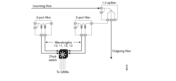
Figure 6-10 shows the optical design for Dhub D. Dhub D is similar to Dhub A, except that it does not feed any subtended Dhubs. Because of this, the optical design for Dhub D is identical to that for Dhub A—with the exception that the combiner from Dhub A is not needed.
Figure 6-10 Middle Node Details: Dhub D
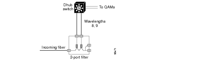
Figure 6-11 shows the optical design for Dhub C. Because Dhub C is an end node, it uses a single 2-port filter to extract the wavelengths that terminate on the Dhub switch.
Figure 6-11 End Node Details: Dhub C
![]()
![]()
![]()
![]()
![]()
![]()
![]()
![]()
Posted: Mon Mar 13 11:08:53 PST 2006
All contents are Copyright © 1992--2006 Cisco Systems, Inc. All rights reserved.
Important Notices and Privacy Statement.