|
|

Table Of Contents
Solution Overview
This chapter presents the following major topics:
Solution Description
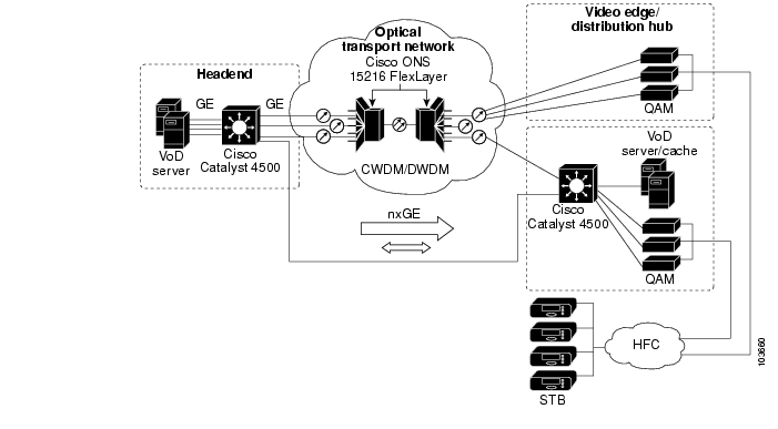
The Cisco Gigabit-Ethernet Optimized VoD Solution, Release 1.1 enables cable operators and MSOs (multiple system operators) to offer Video on Demand (VoD) services to consumer customers over their existing hybrid fiber coax (HFC), with existing next-generation digital set-top boxes. The solution leverages a Gigabit Ethernet (GE) transport network between the headend, where the video servers reside, to the distribution hub (Dhub), where the HFC network terminates. Cisco switches are used in the headend and, optionally, in the Dhub. This solution uses Cisco Catalyst 4500 series switches, and its high-level architecture is depicted in Figure 1-1.
MPEG-2 video is (1) unicast from the video server to the switch; (2) transported from the switch through Gigabit Ethernet interface converters (GBICs; not shown) over an optical Ethernet network between Cisco ONS 15216 Metro FlexLayer DWDM 100-GHz terminal filters at each end; (3) delivered to GE quadrature amplitude modulation (QAM) devices (often referred to simply as QAMs); (4) and then modulated onto the HFC plant for viewing by the authorized user, through a set-top box (STB). See also Architecture and Scope. This solution uses both third-party QAM devices and the Cisco uMG9820 QAM Gateway.
Note
For documentation on the Cisco uMG9820 QAM gateway, see Cisco uMG9820 QAM Gateway at the following URL:
http://www.cisco.com/univercd/cc/td/doc/product/cable/vod/umg9820/index.htmThe intelligent switched infrastructure provided in this solution reduces the overall complexity and operational costs of the network, while permitting scalability for future growth.
Key Applications
Some key applications for this solution include the following:
•
In this application, both new and older releases are offered by the MSO for on-demand viewing.
•
This application provides on-demand viewing of content from premium cable stations. Available content is managed by the premium network, not the MSO. The MSOs store the content locally on their VoD servers, but the network chooses what content is stored there, and how often it is refreshed. The content consists of movies, as well as original programming from the network.
•
This application uses content specifically developed for Video on Demand. This content is typically targeted at specific demographics, such as enthusiasts or consumers with a specific area of interest.
•
For this application, traditional linear network programming is put into the on-demand application. Consumers can view programming when they want to view it. This application can be the highest-volume form of VoD.
Architecture and Scope
The Cisco Gigabit-Ethernet Optimized VoD Solution, Release 1.1, consists of Cisco transport and edge components as identified in Figure 1-1.
Note
Throughout this document, "QAM device" refers to both third-party devices and the Cisco uMG9820 QAM Gateway.For a listing of third-party components and vendors referenced in this solution, see the following:
•
Figure 1-1 High-Level Architecture of the Cisco Gigabit-Ethernet Optimized VoD Solution, Release 1.1
Note the following:
•
•
Basic Solution Scenarios
All Ethernet topologies in this release of the Cisco Gigabit-Ethernet Optimized VoD Solution, Release 1.1 include an Ethernet switch/router in the video headend. There are two main Ethernet topology choices for video transport. The topology choices depend on whether or not the Dhub has Ethernet switching capability.
The following sections introduce two solution scenarios, and provide a high-level comparison between the two:
Switch in Dhub
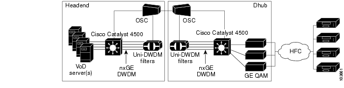
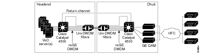
This basic scenario uses a switch at the distribution hub (Dhub), with either a dedicated GE bidirectional wavelength for provisioning and control information, or an arbitrary IP return path that already exists. Figure 1-2 and Figure 1-3 show optical and IP topologies, respectively, of the switch-in-Dhub scenario with a dedicated GE return path. The optical topologies are variations of the physical connections between the switches. The configurations on the switches do not change.
Figure 1-2 Switch in Dhub: Optical Topology—Dedicated GE Return Path
Figure 1-3 Switch in Dhub: IP Topology—Dedicated GE return path
No Switch in Dhub
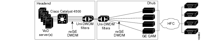
The other basic scenario does not include a switch at the Dhub. In this case, the GE QAM device has some basic Ethernet switching capability to aggregate responses from multiple, daisy-chained GE QAM devices over a single return path. In the no-switch-in-Dhub scenario, the GE QAM devices can be connected directly to the headend switch, either individually or in groups of three. Since each of the Harmonic NSG QAM devices used in this release of the solution handles about 300 Mbps worth of video data, two NSG QAM devices can be daisy-chained off another NSG QAM device that is connected directly to the headend switch. The master QAM device will forward any traffic not addressed to itself to other members of the daisy-chain. Figure 1-4 and Figure 1-5 show optical and Ethernet topologies, respectively, of the no-switch-in-Dhub scenario.
For detailed configuration information, see "Implementing and Configuring the Solution.".
Figure 1-4 Optical Topology
Figure 1-5
Ethernet Topology
In customer deployments, all solution components are located in either a video headend site or a Dhub site. The basic solution topology is an Ethernet hub-and-spoke topology between the headend site and multiple Dhub sites. The Ethernet hub-and-spoke topology can be built in either physical hub-and-spoke or physical- ring fiber environments. When the solution is deployed in networks that use physical ring topologies, the physical ring networks must be converted to an Ethernet hub-and-spoke network at the optical layer.
Note
Scenario Feature Comparison
Table 1-1 provides a high-level comparison of the features of the two scenarios.
Table 1-1 High-Level Comparison of Scenario Features
Optical redundancy
yes
yes
Dhub return channel
yes
no
See Optical Topology.
Automatic population of MAC bridging table
yes
no
See Manual Population of ARP and Bridging Tables on the Dhub Switch.
Automatic population of ARP table
yes
no
Dynamic IP routing
yes
no
See Ethernet Topology.
Dynamic load balancing
yes
no
Solution Components
This solution uses the following basic components:
•
•
Optical Transport Network
The optical portion of the solution consists primarily of a unidirectional optical network to support the video streams. This consists of dense wavelength-division multiplexing (DWDM) gigabit interface converters (GBICs) in the headend switch connecting to a multiplexing unidirectional filter. On the Dhub side is a demultiplexing unidirectional filter that breaks out the individual wavelengths (content streams) and hands them either to a Cisco Ethernet switch, or directly to the GE QAM devices. If individual streams are handed off to a switch, this hand-off would occur to a receive-only GBIC. (For more information, see DWDM GBICs in the Headend Switch.)
The Cisco Gigabit-Ethernet Optimized VoD Solution, Release 1.1 uses 32 wavelengths of the C-Band's 100-GHz ITU DWDM channels. There are eight bands of four wavelengths, allowing a bandgap of a single 100-GHz channel to remain unused between each four-wavelength group. Thus, to cover all 32 wavelengths, 32 individual DWDM GBICs, each representing an individual color of the total transmitted spectrum, are used. (For more information, see Filters.)
Note
DWDM GBICs in the Headend Switch
Many MSOs have a single unidirectional optical link between the headend and the Dhub. DWDM (as apposed to CWDM) is typically chosen as the optical multiplexing technology, because the distance between the headend and Dhub often exceeds the CWDM range.
Cisco GBICs are hot-swappable devices that plug into a GE port, linking the port with the network. The solution uses DWDM optical components that include DWDM lasers on switches used for transmission. The DWDM GBICs used to terminate the unidirectional links in the Dhub switch have receive-only capability.
GE Bidirectional Links
CWDM or DWDM can potentially be used to handle the return path if done over a dedicated GE wavelength. In either scenario, a segmented bidirectional link can either be parallel to the unidirectional video links, or can use any bidirectional network. In fact, where other networks participate in locations of the solution components, as in a DOCSIS network, the bidirectional link does not have to be parallel.
This link can be used for the return path for provisioning information from switches and other devices connected to the unidirectional downstream link. It is assumed that all downstream wavelengths share the same fibers whether they are CWDM or DWDM. Upstream wavelengths use a second physical layer.
Filters
Cisco offers 16 two-channel filters, and 4 eight-channel filters. Any combination of these filters can be used to support multiple GE channels (or "colors" in an optical context). The filter in the headend is configured as a DWDM multiplexer, and the filter in the Dhub is configured as a DWDM demultiplexer. The use of unidirectional filters saves the cost of return path optics in both locations, as well as of a dedicated laser for each channel deployed in the Dhub.
All filters have an incoming or outgoing fiber port (for pass-through). There is also a monitor, or tap, port, which can be used for optical-performance monitoring of all wavelengths on the fiber when it is attached to an external optical monitoring system. Finally, there are two or eight individual-wavelength ports that filter specific wavelengths in or out.
When the need for more than a gigabit of traffic is apparent, or when the need for additional DWDM wavelengths is envisioned for multiple forward channels or one or more return channels from the Dhub to the headend, additional unidirectional filters can be used to provide asymmetric DWDM connectivity between the headend and the Dhub. This scenario also uses a set of bidirectional DWDM GBICs in the headend and Dhub switches. The DWDM output of the GBIC in the headend switch is driven as one wavelength in the filter complex that is used between the headend and Dhub sites. The DWDM output of the GBIC in the Dhub switch is also driven as one wavelength in a unidirectional filter complex that is used between Dhub and headend sites. The two unidirectional filters allow asymmetric bandwidth to be provisioned between the sites.
Ethernet Switches
The switches that have been tested and are supported in this release of the Cisco Gigabit-Ethernet Optimized VoD Solution, Release 1.1 are members of the Cisco Catalyst 4500 series. The Catalyst 4507R is used for the headend switch to gain maximum density and redundancy capabilities. Any of the other members of the series, such as the Cisco Catalyst 4503, can be used as the switch in the Dhub, where redundancy is not of great concern.
To ensure that the GE ports can be driven close to 100% link utilization for video, the Ethernet switches in the solution must be capable of operating their Gigabit Ethernet interfaces in a unidirectional, nonblocking manner, in both transmit and receive directions. For example, the switch must behave normally (not set off alarms, for instance) when only receiving Ethernet frames on a given interface, or only transmitting frames on a given interface. This functionality can be limited to nonblocking GE ports only on the Cisco 4500 series switch used in the solution.
Note
http://www.cisco.com/univercd/cc/td/doc/product/lan/cat4000/index.htmVideo Servers
For this solution, VoD servers will be supplied by third-party VoD server vendors. Table 1-2 lists the capabilities of the VoD servers used in Release 1.0 of the solution.
Table 1-2 Capabilities of VoD Servers Used in the Cisco Gigabit-Ethernet Optimized VoD Solution, Release 1.1, Release 1.0
ProductConcurrent/
MediaHawkNo
No
No
No
No
Yes
Yes
Yes
SeaChange/
ITV Media ClusterNo
No
No
No
No
No
No
Yes
nCube/
n4x On-Demand ServerNo1
No2
No
Yes3
No4
Yes
Yes
Yes
1 Servers are interconnected by means of an internal scalable network.
2 No failover at optical layer, but failover is supported at a higher layer.
3 Optimized for unidirectional video delivery.
4 No failover at the GE physical link layer, but failover is supported at a higher layer.
Note
Gigabit Ethernet QAM Devices
These devices take MPEG streams arriving over GE transport in UDP packets and use QAM modulation and RF upconversion to introduce the video onto RF channels on the HFC plant. Video edge equipment for this release of the solution will be supplied by third-party QAM vendors. Table 1-3 lists the capabilities of the QAM devices used in Release 1.1 of the solution. (Versions of the Harmonic NSG earlier than version 2.1 do not support GE redundancy, and provide unreliable ARP responses.)
Table 1-3 Capabilities of QAM Devices Used in the Cisco Gigabit-Ethernet Optimized VoD Solution, Release 1.1
ProductHarmonic/
NSGYes
Yes
Yes
Yes
Yes
Yes
Yes
Cisco/
Cisco uMG9820 QAM Gatewaywww.cisco.com/univercd/cc/td/doc/product/cable/vod/umg9820/index.htm
No
Yes
Yes
Yes
No
Yes
Yes
Note
Element Management
Provisioning and fault management of Cisco Catalyst 4500 series switches for the solution are performed through the command line interface (CLI) of the Cisco IOS. Fault management is not provided for the passive optical components of the solution, including multiplexers, demultiplexers, splitters, and the OSC (optical supervisory channel).
Note
![]()
![]()
![]()
![]()
![]()
![]()
![]()
![]()
Posted: Mon Mar 13 12:17:03 PST 2006
All contents are Copyright © 1992--2006 Cisco Systems, Inc. All rights reserved.
Important Notices and Privacy Statement.