|
|

Table Of Contents
Designing the Solution
In customer deployments, all Cisco Gigabit-Ethernet Optimized VoD Solution components will be located in either a video headend site or a distribution hub (Dhub) site. The basic topology is an Ethernet hub-and-spoke topology between the headend site and multiple Dhub sites. The Ethernet hub and spoke topology can be built in either physical hub-and-spoke or physical fiber-ring environments. When the solution is deployed in networks that use physical ring topologies, the ring networks must be converted to an Ethernet hub-and-spoke network at the optical layer. (Different optical layer topologies have no effect on either the operation or performance of Gigabit Ethernet.)
Note
For instructions for converting a ring network to a hub-and-spoke network, using physical dark-fiber media and xWDM methods, see "Deploying the Cisco Gigabit-Ethernet Optimized VoD Solution in Fiber Ring Topologies."
All Ethernet topologies in the initial releases (Release 1.0 and Release 1.1) of the solution include an Ethernet switch in the video headend. There are two main Ethernet topology choices for video transport. The topology choices depend on whether or not there is an Ethernet switching capability in the Dhub.
This chapter presents the following major topics:
Switch in the Dhub
This section presents the following topics:
Ethernet Topology
Figure 2-1 illustrates the Ethernet topology used in the Cisco Gigabit-Ethernet Optimized VoD Solution for Ethernet switching in the Dhub. This section presents the following topics:
•
•
•
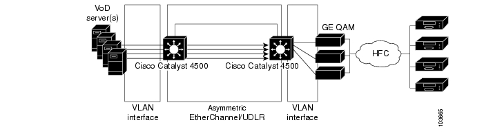
Figure 2-1 Switch in Dhub: Ethernet Topology—Dedicated GE Bidirectional Wavelength
This topology allows the switching path to be broken into three sets of component links:
•
•
•
Since multiple equal-cost links connect the headend and Dhub switches, load balancing will be applied. Both Layer 3 IP and EtherChannel load balancing are used in this solution. Depending on the number of ports used to connect the headend switch to the Dhub switch, one or both of these load-balancing techniques are used. The use of load balancing simplifies provisioning, because the links between the headend and Dhub switches appear as one large pipe to both routing protocols, as well as to the IP forwarding logic. (See Enabling Load Balancing.)
This topology also allows for a control-plane back channel between the Dhub and headend switches. The video transport interfaces between the headend and Dhub switches are unidirectional, helping to reduce cost. Because of this, a separate return path link must be used.
To allow IP routing and other protocols to work transparently, it is important to bind the return path link There are two ways to do this:
•
•
In Release 1.0 and Release 1.1 of the Cisco Gigabit-Ethernet Optimized VoD Solution, either an asymmetric EtherChannel or UDLR are used for the return-channel connectivity between the headend and Dhub switches. Which method to use will depend on the specifics of the connectivity between the switches. An asymmetric EtherChannel will be used when the headend and Dhub switches are directly connected with a single EtherChannel group. In more-complex connectivity scenarios, UDLR must be used in place of the asymmetric EtherChannel. These scenarios are described below.
IP Topology
Figure 2-2 illustrates the IP topology of the Cisco Gigabit-Ethernet Optimized VoD Solution for the switch-in-Dhub scenario.
Figure 2-2 Switch in Dhub: IP Topology—Dedicated GE Return Path
There are three logical IP segments:
•
•
•
If the headend switch is connected to the Dhub switch with a single EtherChannel group, an asymmetric EtherChannel will be used. As a result, there will be a single IP interface on the headend and Dhub switches for this EtherChannel group.
The use of an asymmetric EtherChannel means that flows from the headend to the Dhub will be distributed across all of the links in the EtherChannel group. Traffic from the headend to the Dhub will consist of video flows, but may also include nonvideo data such as network management traffic and IP routing updates.
For configuration details, see Establishing Interfaces on the Headend Switch, and Establishing Interfaces on the Dhub Switch.
Designing for Growth
The following sections provide recommendations for network designers to accommodate future growth in capacity between the headend and the Dhub:
•
Load-Balancing Strategies
This section introduces issues and strategies related to EtherChannel and IP load balancing. It is valid to configure EtherChannel, IP load balancing, or a combination of EtherChannel and IP load balancing across a set of ports from a headend to a Dhub switch. In theory, it should be possible to use any of the above three load-balancing techniques, along with any combination of EtherChannel and IP load balancing, for any number of ports between those switches. However, limitations in the load-balancing architecture and its implementation on the Cisco Catalyst 4500 series switches force restrictions on how load balancing can be used for this solution. The restrictions—and strategies to deal with them—are presented below.
The Cisco Catalyst 4500 series switches implement a stateless, equal-cost load-balancing algorithm in hardware for both EtherChannel and IP load balancing. Because the hardware supports only equal-cost load balancing, all EtherChannel groups should have the same number of ports assigned to them when EtherChannel and IP load balancing are used in combination. This restricts valid configurations of EtherChannel in combination with IP load balancing to cases where the number of links in each EtherChannel group, multiplied by the number of EtherChannel interfaces per Dhub, equals the number of ports between the headend and Dhub. Consider also the following:
•
•
Table 2-1 lists the combinations of EtherChannel and IP load balancing that have been shown, through both simulation and system testing, to exhibit optimal load-balancing behavior for Release 1.0 and Release 1.1 of the Cisco Gigabit-Ethernet Optimized VoD Solution.
Caution
Notice that there is more than one potential load-balancing configuration for some values of headend-to-Dhub ports. For example, load balancing for 4 ports between a headend and Dhub switch can be configured by using either 1 EtherChannel group of 4 ports or 4 separate physical Layer 3 interfaces. The best configuration to use in these cases will depend on a number of factors, including IP addressing scheme, ease of configuration, and flexibility in adding ports as capacity demands increase.
Note
To make EtherChannel load balancing more deterministic, only the destination IP port number is used as the input to the load-balancing function. The Harmonic NSG QAM device (along with other GE QAM devices) uses a static mapping to derive the QAM channel and MPEG program number from the destination port number of an incoming MPEG stream. Consequently, a fully loaded QAM will have a known set of destination IP port values for all the MPEG streams that it services.
Strategies to Facilitate Expansion
This section describes strategies that can be used to facilitate the growth in traffic to a Dhub by increasing the number of ports between a headend and Dhub switch. These strategies use the information in Table 2-1 to define different strategies for increasing capacity, depending on the requirements of the network. Other expansion strategies may be derived from the information in Table 2-1 to match best the requirements of network designs that do not match the objectives of the strategies listed in this section.
In some network designs, it is important to simplify provisioning by avoiding the renumbering of IP interfaces as capacity requirements increase. In these cases, it is best to use a combination of EtherChannel and IP load balancing to increase port capacity. This results in a strategy where port capacity is increased in units of EtherChannel groups. With the information in Table 2-1, this strategy can be implemented by using a combination of 2- and 4-port EtherChannel group sizes. Table 2-2 illustrates the subset of the combinations of Table 2-1 that could be used to implement this strategy. While this strategy simplifies provisioning by not requiring the renumbering of IP interfaces as capacity increases, it does not allow as much flexibility in port number increments as is shown in Table 2-1.
If the renumbering of IP interfaces is not an issue for a particular network design, an alternative strategy could be used in which (1) IP load balancing alone is used for headend-to-Dhub port combinations of 1 to 8, and (2) a combination of IP and EtherChannel load balancing is used to support more than 8 ports. Table 2-2 illustrates the subset of the combinations of Table 2-1 that could be used to implement this strategy. The strategy illustrated in Table 2-3 provides the full flexibility of Table 2-1, while minimizing the renumbering of IP subnets as capacity requirements increase.
UDLR
When multiple EtherChannel groups are configured between the headend and Dhub switches, it is inefficient to require an Ethernet return channel for each interface. Consequently, Cisco UniDirectional Link Routing (UDLR) is used on all of the unidirectional IP interfaces configured between the two switches. (This is discussed further in Subtended Dhubs.) The configuration of the UDLR interface creates a second IP interface on the Dhub switch.
When UDLR is configured, the GRE tunnel for the UDLR interface will end up using the bidirectional Ethernet port that was configured to be part of the asymmetric EtherChannel. OSPF cost metrics are configured on the Dhub switch to direct upstream IP packets through the bidirectional IP interface, rather than through the UDLR back-channel interface. This is needed because the UDLR back channel is process-switched, and will consequently have very low throughput.
Note
QoS
To enable video streams to be serviced ahead of nonvideo traffic, QoS must be enabled on the headend switch. To achieve this, a policy-map statement is mapped to an access control list (ACL) on the headend switch interface that is connected to the VoD servers. These statements will mark video traffic with "DSCP EF" and nonvideo traffic with "DSCP 0." If a management port is connected to the headend switch, all packets arriving on this port will be marked with "DSCP 0." Egress QoS will be enabled on the Ethernet ports of asymmetric EtherChannel groups connected to Dhubs.
Packets marked with "DSCP EF" will be serviced by a priority queue. Packets marked with any other DSCP value will be serviced by a weighted queue configured for 80% of the physical link bandwidth. This configuration allows the video load to be distributed evenly cross all members of an EtherChannel group, while ensuring that video is always transmitted in a timely manner.
Note
For configuration details, see Establishing Quality of Service (QoS).
OSPF
OSPF is used as the Internet routing protocol in Release 1.0 and Release 1.1 of the Cisco Gigabit-Ethernet Optimized VoD Solution. OSPF is enabled on all IP interfaces in the headend and Dhub switches. OSPF populates the routing table on the headend switch with routes to the QAM devices, and also enables equal-cost load balancing when multiple IP interfaces are configured between the headend and Dhub switches.
Subtended Dhubs
Some topologies for the Cisco Gigabit-Ethernet Optimized VoD Solution will include subtended Dhubs. A subtended Dhub is a Dhub whose bidirectional link is connected to another Dhub, and whose unidirectional link(s) are connected to the headend switch. Refer to Figure 2-3, which illustrates the architecture for subtended Dhubs and return channels, with support for bidirectional and unidirectional interfaces. When subtended Dhubs are used, the upstream Dhubs will have more than one bidirectional link connected to them. On the upstream Dhubs, each of the bidirectional links will appear as a separate IP interface.
Since the bidirectional interface to the subtended Dhub is not directly connected to the headend switch, but the unidirectional interface(s) are, an asymmetric EtherChannel cannot be used. Instead, UDLR is used for the return channel for all IP interfaces between the Dhub and the headend switch, as discussed in UDLR. When UDLR is configured, the GRE tunnel for the UDLR interface will use the least-cost IP path back to the headend switch. This will turn out to be the combination of the bidirectional (asymmetric) Ethernet link (EtherChannel) between (1) the subtended Dhub and upstream Dhub, and (2) the Ethernet port that was configured to be part of the asymmetric interface between the upstream Dhub and headend switch. As noted earlier, the configuration of the UDLR interface ends up creating a second IP interface on the subtended Dhub switch. Figure 2-3 illustrates this second path from the headend to subtended Dhub B.
Caution
Normally, the second path between the headend and subtended Dhub B will not be selected by routing protocols, because it will have a higher cost than the directly connected link between the switches. However, if the directly connected link fails, the second path will be chosen for VoD traffic. The use of the second path by VoD streams would likely cause congestion and result in degraded video quality for VoD traffic going from the headend to the subtended Dhub. In addition, the use of the second path would cause VoD streams from the headend to both Dhubs A and B to be routed through the EtherChannel group from the headend to Dhub A. Because of this, a link failure of the directly connected link from the headend to Dhub B would result in degraded video quality for customers of both Dhub B and Dhub A.
Figure 2-3 Subtended Dhubs and Return Channel Architecture
To prevent this scenario from occurring, the IP routing configuration must be modified to prevent the second path from the headend to Dhub B from being used by the headend switch. (Though the second path is still advertised and is entered into the switch's database, it is blocked from the routing table.) This can be accomplished by configuring OSPF distribution lists on the headend switch. A distribution list filters OSPF routes received on a particular interface to include or exclude routes to specific subnets. Since the headend switch is supposed to use only the directly connected EtherChannel to send packets to the QAMs in a particular Dhub, a "permit" access control list can be configured on each IP interface in the headend switch. The ACL for each interface will contain one permit entry for the QAM subnet on the directly connected Dhub switch. In this way, the headend switch will learn only a single route to the QAMs in each Dhub. That route will use the directly connected link to the Dhub.
Note
QAM Device Connectivity
Some third-party QAM devices can be daisy chained. These devices support basic packet switching to allow IP packets not destined for one QAM device to be passed to the other QAM devices in the chain. Even though the Dhub switch can provide a separate fiber to each QAM device, daisy chaining has the advantage of reducing the number of GE ports needed in the Dhub. However, the risk of failure is increased, because a failure on the link between the switch and the first QAM device causes all devices in the chain to fail. In most situations, more than a single GE worth of traffic will be required between the QAM device complex and the Dhub switch. In these cases, each "master" GE QAM device should have its own connection to the Dhub switch.
When QAM dvices that are not capable of daisy chaining are used in this solution, each QAM device must be connected to the Dhub switch through a separate bidirectional GE port. The capabilities of the QAM devices used in the Cisco Gigabit-Ethernet Optimized VoD Solution are shown in Table 1-3.
Note
Optical Topology
Many multiple system operators (MSOs) have a single unidirectional optical link between the headend and a Dhub. DWDM (as opposed to CWDM) is typically chosen as the optical multiplexing technology, because the distance between the headend and Dhub often exceeds the CWDM range.
The Cisco Gigabit-Ethernet Optimized VoD Solution uses DWDM optical components that are cost-reduced to include DWDM lasers on nodes that are used for transmission. For example, the DWDM GBICs used to terminate the unidirectional links in the Dhub switch have receive-only capability. This saves the cost of the DWDM laser on each receive port. The Cisco 15216 FlexLayer DWDM filters have also been cost-reduced, so that the filter in the headend is capable only of DWDM multiplexing, and the filter in the Dhub is capable only of DWDM demultiplexing. This eliminates the need for passive optics in both components and for a DWDM laser for the filter in the Dhub—with attendant cost savings.
The back channel between the headend and Dhub switches requires a second fiber between the headend and the Dhub. This second fiber may be part of an existing SONET infrastructure that is being redeployed for GE transport, or it may be part of a side-by-side data network already deployed by the MSO. In many cases, however, a second fiber will not already be in use and will have to be allocated for use in the video network.
There are several options for implementing the GE back channel:
•
•
The best choice for a particular design depends on the existing infrastructure and future applications that may be required.
DWDM over Dark Fiber
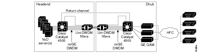
DWDM over dark fiber will typically be used when a return fiber between the headend and Dhub sites is not already in use. DWDM over dark fiber uses a set of bidirectional DWDM GBICs in the headend and Dhub switches. The DWDM output of the GBIC in the headend switch is driven as one wavelength in the Uni-DWDM filter complex between the headend and Dhub sites. The DWDM output of the GBIC in the Dhub switch directly drives a return fiber connected to the receive side of bidirectional GBIC in the headend switch. This option does not need additional optical components to provide the back-channel functionality. Figure 2-4 illustrates both the Ethernet and optical layers used for the DWDM-over-dark-fiber GE return path option for the switch-in-Dhub scenario.
Figure 2-4 Switch in Dhub: Optical Topology—DWDM over Dark Fiber GE Return Path
DWDM Multiplexing Using a Second Set of Uni-DWDM Filters
When DWDM fiber is already available, or when the need for multiple DWDM wavelengths is envisioned for the return channel from Dhub to headend, a second unidirectional uni-DWDM filter can be used to provide asymmetric DWDM connectivity between headend and Dhub. This scenario also uses a pair of bidirectional DWDM GBICs in the headend and Dhub switches. The DWDM output of the GBIC in the headend switch is driven as one wavelength in the filter complex between headend and Dhub sites. The DWDM output of the GBIC in the Dhub switch is also driven as one wavelength in a unidirectional filter complex between Dhub and headend sites. The two unidirectional filters allow asymmetric bandwidth to be provisioned between headend and Dhub sites. Figure 2-5 illustrates the asymmetric DWDM return path option for the switch-in-Dhub scenario.
Figure 2-5 Switch in Dhub: Optical Topology—DWDM with Return DWDM MUX
CWDM Multiplexing Using the Cisco 15216 OSC-1510
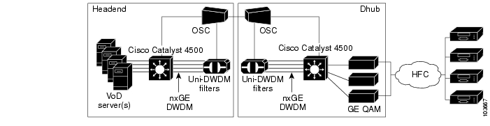
When the fiber distance between the headend and Dhub sites allows it, the Cisco 15216 OSC-1510 can be used to multiplex a bidirectional CWDM link into the downstream DWDM wavelengths. In this scenario, standard bidirectional CWDM GBICs can be used in the headend and Dhub switches. The downstream CWDM channel is multiplexed/demultiplexed onto the DWDM fiber after and before, respectively, the uni-DWDM filters. The upstream CWDM channel is driven on a return fiber dedicated for this purpose. The use of the OSC (optical supervisory channel) and CWDM filters can reduce the cost of implementing the optical return path over the DWDM scenarios described above. However, because of the distance limitations in multiplexing CWDM into the optical path, this approach is recommended only for fiber topologies where long-distance connections are not needed. Figure 2-6 illustrates the CWDM return path option for the switch-in-Dhub scenario.
Note
Figure 2-6 Switch in Dhub: Optical Topology—CWDM Return Path
No Switch in the Dhub
This section presents the following major topics:
Ethernet Topology
Figure 2-7 illustrates the Ethernet topology when the Cisco Gigabit-Ethernet Optimized VoD Solution is deployed with no switching capability in the Dhub. This topology is extremely simple, because there are essentially only two segments in the Ethernet switching path.
Figure 2-7 No Switch in Dhub: Ethernet Topology
Note
Release 1.0 and Release 1.1 of the Cisco Gigabit-Ethernet Optimized VoD Solution support two different types of Layer 2 and Layer 3 switching configurations for this topology:
•
•
These are described in the following sections.
Layer 2 Switching
In Layer 2 switching, all of the VoD servers and QAM devices will appear in the same IP subnet. The Cisco Catalyst 4500 switch must be configured to perform MAC layer bridging between all of its connected interfaces. Since no back channel will be available between the QAM devices and the switch, the MAC layer bridge table entries for the interfaces between the headend and Dhub must be populated manually. In addition, because there is no back channel between the headend and the Dhub, ARP requests from the VoD server to the QAM devices will not work. This means that the ARP table in the VoD server must also be populated manually. Figure 2-8 illustrates the Ethernet topology for Layer 2 switching for the no-switch-in-Dhub scenario.
Figure 2-8 No Switch in Dhub: Ethernet Topology for Layer 2 Switching
IP Switching Between the Headend and All Dhubs
When IP switching is used between the headend and all the Dhubs, two interfaces must be configured on the headend switch:
•
These links will all be terminated through a MAC layer bridge group into a single IP interface on the headend switch.
•
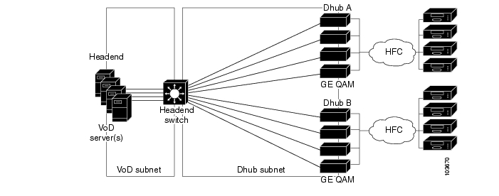
These links will also be terminated into a single IP interface on the headend switch. Figure 2-9 illustrates the topology for switching between the headend and all Dhubs for the no-switch-in-Dhub scenario.
Figure 2-9 No Switch in Dhub: Topology for IP Switching Between the Headend and All Dhubs
While this also requires manual configuration, the configuration will be reduced, because IP discovery protocols can be used on the bidirectional link between the VoD servers and the headend switch. For example, ARP is used to populate the ARP table on VoD servers that support ARP. The limitations of VoD servers in regards to ARP functionality are shown in Table 1-2.
For VoD servers that do not support an ARP sender (such as the SeaChange VoD server), a subset of HSRP (Hot Standby Routing Protocol) functionality is configured on the Ethernet ports connected to the VoD servers. In addition to implementing a failover protocol, HSRP supports the configuration of a virtual MAC address that can be shared between the active and standby HSRP nodes. For VoD servers that do not support ARP, HSRP is configured with only one interface in the HSRP group. As a result, HSRP failover will not be enabled. Instead, an HSRP virtual MAC address will be configured to replace the native MAC address of the VLAN interface. The HSRP virtual MAC address allows ARP table configuration on the VoD server to be made independently of the headend switch to which it is connected.
Because the Dhubs are directly connected to the headend switch, the IP address and subnet mask assigned to the Dhub VLAN interface on the headend switch will populate the IP switching table with forwarding information needed to forward packets to the Dhubs.
IP Switching Between the Headend and Each Dhub Link
When IP switching is used between the headend and each Dhub, there will be one interface configured on the headend switch for all of the ports connected to VoD servers and one interface configured for each Dhub that the headend switch is connected to. This configuration trades off increased complexity in the configuration of static routes on the headend switch for decreased complexity in configuration of the bridging table as compared to the scenario described in IP Switching Between the Headend and All Dhubs. Figure 2-10 illustrates the topology for IP switching between the headend and each Dhub link for the no-switch-in-Dhub scenario.
Figure 2-10 No Switch in Dhub: Topology for IP Switching Between the Headend and Each Dhub Link
This configuration also provides a straightforward migration path to the first implementation phase of RFC 3077. RFC 3077 describes a protocol that emulates a logical bidirectional link between two nodes that are directly connected with a unidirectional link and indirectly connected with a separate bidirectional IP path. While RFC 3077 can be used to emulate a bidirectional multipoint network (a multipoint MAC layer bridged network in 802.3 environments), it is simpler to emulate a bidirectional point-to-point link using RFC 3077. Because of this, the first implementation of RFC 3077 in the Cisco IOS will emulate a bidirectional point-to-point link whose endpoints terminate as IP layer interfaces. Since the configuration described in this section breaks the IP topology into one subnet per link connected to Dhubs, the initial implementation of RFC 3077 can be used to provide a back-channel capability for each of the links connected to Dhubs. The RFC 3077 back channel can be used to carry ARP requests between the headend switch and the QAM devices to dynamically populate the ARP table on the headend switch and on the QAM devices.
In this configuration, each link from the headend switch to each Dhub resides in a separate subnet. As a result, there will be one physical interface configured on the headend switch for each link connected to a Dhub. In cases where there are multiple links to a Dhub, the outbound interfaces may be included in a single VLAN to use network addresses more efficiently. Otherwise, each interface will require a unique subnet.
Since the QAM devices are directly connected to the headend switch, the IP address and subnet mask configured for each VLAN interface will populate the IP switching table with the forwarding information needed to forward packets to the Dhubs connected on that link.
Manual Population of ARP and Bridging Tables on the Dhub Switch
Normally, the switch discovers the IP and MAC addresses of the destination interface (for the QAM devices, the GE port for Layer 2 switching). The switch then populates (1) its bridging table with pairs consisting of a MAC address and the associated physical port, and (2) its ARP table with pairs consisting of a MAC address and an IP address.
To accommodate QAM devices that do not send ARP replies, you will need to configure the ARP tables manually on the Dhub switch. If multiple QAM devices are connected to the Dhub switch in a single VLAN and they do not send ARP replies, you should manually populate the MAC address table to avoid possible port flooding on the VLAN. If the QAM devices are connected through Layer 3 ports, or if each QAM device is in its own VLAN, then the MAC address table does not have to be populated manually.
Note
Optical Topology
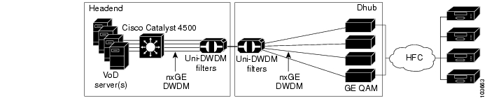
Figure 2-11 illustrates both the Ethernet and optical layers used for the no-switch-in-Dhub option in Release 1.0 and Release 1.1 of the Cisco Gigabit-Ethernet Optimized VoD Solution.
Note
Figure 2-11 No Switch in Dhub: Optical Topology
![]()
![]()
![]()
![]()
![]()
![]()
![]()
![]()
Posted: Mon Mar 13 10:51:50 PST 2006
All contents are Copyright © 1992--2006 Cisco Systems, Inc. All rights reserved.
Important Notices and Privacy Statement.