|
|

Table Of Contents
Cisco Wireless LAN Solution Overview
Multiple-Controller Deployments
Cisco WLAN Solution Wired Security
Layer 2 and Layer 3 LWAPP Operation
Radio Resource Management (RRM)
Cisco Wireless LAN Controllers
Primary, Secondary, and Tertiary Controllers
Same-Controller (Layer 2) Roaming
Inter-Controller (Layer 2) Roaming
Inter-Subnet (Layer 3) Roaming
Cisco WLAN Solution Mobility Groups
Cisco WLAN Solution Wired Connections
Cisco WLAN Solution Wireless LANs
Enhanced Integration with Cisco Secure ACS
Intrusion Detection Service (IDS)
Cisco Wireless LAN Controllers
Cisco 2000 Series Wireless LAN Controllers
Cisco 4100 Series Wireless LAN Controllers
Cisco 4400 Series Wireless LAN Controllers
Cisco 2000 Series Wireless LAN Controller Model Numbers
Cisco 4100 Series Wireless LAN Controller Model Numbers
Cisco 4400 Series Wireless LAN Controller Model Numbers
About the Management Interface
Cisco Wireless LAN Controller Memory
Cisco Wireless LAN Controller Failover Protection
Cisco Wireless LAN Controller Automatic Time Setting
Network Connections to Cisco Wireless LAN Controllers
Cisco 4100 Series Wireless LAN Controller VPN/Enhanced Security Module
Cisco 1000 Series IEEE 802.11a/b/g Lightweight Access Points
Cisco 1030 Remote Edge Lightweight Access Points
Cisco 1000 Series Lightweight Access Point Part Numbers
Cisco 1000 Series Lightweight Access Point External and Internal Antennas
Cisco 1000 Series Lightweight Access Point LEDs
Cisco 1000 Series Lightweight Access Point Connectors
Cisco 1000 Series Lightweight Access Point Power Requirements
Cisco 1000 Series Lightweight Access Point Mounting Options
Cisco 1000 Series Lightweight Access Point Physical Security
Cisco 1000 Series Lightweight Access Point Monitor Mode
Using the DNS for Controller Discovery
Autonomous Access Points Converted to Lightweight Mode
Guidelines for Using Access Points Converted to Lightweight Mode
Reverting from Lightweight Mode to Autonomous Mode
Controllers Accept SSCs from Access Points Converted to Lightweight Mode
Using a Controller to Send Debug Commands to Access Points Converted to Lightweight Mode
Converted Access Points Send Crash Information to Controller
Converted Access Points Send Radio Core Dumps to Controller
Enabling Memory Core Dumps from Converted Access Points
Display of MAC Addresses for Converted Access Points
Disabling the Reset Button on Access Points Converted to Lightweight Mode
Configuring a Static IP Address on an Access Point Converted to Lightweight Mode
Rogue Access Point Location, Tagging, and Containment
Web User Interface and the CLI
Cisco WCS Cisco Wireless LAN Controller Autodiscovery
Cisco WCS Alarm Email Notification
Cisco WCS Location Calibration
Cisco 2700 Series Location Appliances
Overview
This chapter describes the components and features of the Cisco Wireless LAN Solution. This chapter contains these sections:
•
Cisco Wireless LAN Solution Overview
•
•
•
•
•
•
•
•
•
•
•
Cisco Wireless LAN Solution Overview
The Cisco Wireless LAN Solution is designed to provide 802.11 wireless networking solutions for enterprises and service providers. The Cisco Wireless LAN Solution simplifies deploying and managing large-scale wireless LANs and enables a unique best-in-class security infrastructure. The operating system manages all data client, communications, and system administration functions, performs Radio Resource Management (RRM) functions, manages system-wide mobility policies using the operating system Security solution, and coordinates all security functions using the operating system security framework.
The Cisco Wireless LAN Solution consists of Cisco Wireless LAN Controllers and their associated lightweight access points controlled by the operating system, all concurrently managed by any or all of the operating system user interfaces:
•
•
•
•
The Cisco Wireless LAN Solution supports client data services, client monitoring and control, and all rogue access point detection, monitoring, and containment functions. The Cisco Wireless LAN Solution uses lightweight access points, Cisco Wireless LAN Controllers, and the optional Cisco WCS to provide wireless services to enterprises and service providers.
The Cisco WCS application is offered in two versions:
•
•
See the "Cisco WCS Base" section and the "Cisco WCS Location" section for more information.
When Cisco WCS Location is used, Cisco Wireless LAN Solution end users can also deploy Cisco 2700 Series Location Appliances, described in Chapter 10, "Configuring and Using Location Appliances." The location appliance enhances the high-accuracy built-in Cisco WCS Location abilities by computing, collecting and storing historical location data, which can be displayed in Cisco WCS. In this role, the location appliance acts as a server to one or more Cisco WCS Servers, collecting, storing, and passing on data from its associated controllers.
Note
Figure 1-1 shows the Cisco Wireless LAN Solution components, which can be simultaneously deployed across multiple floors and buildings.
Figure 1-1 Cisco WLAN Solution Components
Single-Controller Deployments
A standalone Cisco Wireless LAN Controller can support lightweight access points across multiple floors and buildings simultaneously, and supports the following features:
•
•
•
•
Note that some Cisco Wireless LAN Controllers use redundant Gigabit Ethernet connections to bypass single network failures. At any given time one of the redundant Gigabit Ethernet connections is active and the other is passive. Upon a network failure, the active connection becomes passive, and the passive connection becomes active.
Note
Figure 1-2 shows a typical single-controller deployment.
Figure 1-2 Single-Controller Deployment
Multiple-Controller Deployments
Each Cisco Wireless LAN Controller can support lightweight access points across multiple floors and buildings simultaneously. However, full functionality of the Cisco Wireless LAN Solution is realized when it includes multiple controllers. A multiple-Cisco Wireless LAN Controller system has the following additional features:
•
•
•
The following figure shows a typical multiple-controller deployment. The figure also shows an optional dedicated Management Network and the three physical connection types between the network and the controllers.
Figure 1-3 Typical Multi-Controller Deployment
Operating System Software
The Operating System Software controls Cisco Wireless LAN Controllers and Cisco 1000 Series Lightweight Access Points. It includes full operating system security and Radio Resource Management (RRM) features.
Operating System Security
Operating system security bundles Layer 1, Layer 2, and Layer 3 security components into a simple, Cisco WLAN Solution-wide policy manager that creates independent security policies for each of up to 16 wireless LANs. (Refer to the "Cisco WLAN Solution Wireless LANs" section.)
The 802.11 Static WEP weaknesses can be overcome using robust industry-standard security solutions, such as:
•
•
–
–
•
•
•
•
The WEP problem can be further solved using industry-standard Layer 3 security solutions, such as:
•
•
•
–
–
–
The Cisco WLAN Solution IPSec implementation also includes industry-standard authentication using:
–
–
•
•
•
These and other security features use industry-standard authorization and authentication methods to ensure the highest possible security for your business-critical wireless LAN traffic.
Cisco WLAN Solution Wired Security
Many traditional access point vendors concentrate on security for the Wireless interface similar to that described in the "Operating System Security" section. However, for secure Cisco Wireless LAN Controller Service Interfaces, Cisco Wireless LAN Controller to access point, and inter-Cisco Wireless LAN Controller communications during device servicing and client roaming, the operating system includes built-in security.
Each Cisco Wireless LAN Controller and Cisco 1000 series lightweight access point is manufactured with a unique, signed X.509 certificate. This certificate is used to authenticate IPSec tunnels between devices. These IPSec tunnels ensure secure communications for mobility and device servicing.
Cisco Wireless LAN Controllers and Cisco 1000 series lightweight access points also use the signed certificates to verify downloaded code before it is loaded, ensuring that hackers do not download malicious code into any Cisco Wireless LAN Controller or Cisco 1000 series lightweight access point.
Layer 2 and Layer 3 LWAPP Operation
The LWAPP communications between Cisco Wireless LAN Controller and Cisco 1000 series lightweight access points can be conducted at ISO Data Link Layer 2 or Network Layer 3.
Operational Requirements
The requirement for Layer 2 LWAPP communications is that the Cisco Wireless LAN Controller and Cisco 1000 series lightweight access points must be connected to each other through Layer 2 devices on the same subnet. This is the default operational mode for the Cisco Wireless LAN Solution. Note that when the Cisco Wireless LAN Controller and Cisco 1000 series lightweight access points are on different subnets, these devices must be operated in Layer 3 mode.
The requirement for Layer 3 LWAPP communications is that the Cisco Wireless LAN Controllers and Cisco 1000 series lightweight access points can be connected through Layer 2 devices on the same subnet, or connected through Layer 3 devices across subnets.
Note that all Cisco Wireless LAN Controllers in a mobility group must use the same LWAPP Layer 2 or Layer 3 mode, or you will defeat the Mobility software algorithm.
Configuration Requirements
When you are operating the Cisco Wireless LAN Solution in Layer 2 mode, you must configure a management interface to control your Layer 2 communications.
When you are operating the Cisco Wireless LAN Solution in Layer 3 mode, you must configure a management interface to control your Layer 2 communications, and an AP-Manager interface to control Cisco 1000 series lightweight access point-to-Cisco Wireless LAN Controller Layer 3 communications.
Radio Resource Management (RRM)
Radio Resource Management (RRM) allows Cisco Wireless LAN Controllers to continually monitor their associated Cisco 1000 series lightweight access points for the following information:
•
•
•
•
•
Using the collected information, RRM can periodically reconfigure the 802.11 RF network within operator-defined limits for best efficiency. To do this, RRM:
•
•
•
•
•
•
•
•
The RRM solution thus allows the operator to avoid the costs of laborious historical data interpretation and individual Cisco 1000 Series IEEE 802.11a/b/g lightweight access point reconfiguration. The power control features of RRM ensure client satisfaction, and the coverage hole detection feature can alert the operator to the need for an additional (or relocated) Cisco 1000 series lightweight access point.
Note that the RRM uses separate monitoring and control for each of the deployed networks: 802.11a and 802.11b/802.11g. Also note that RRM is automatically enabled, but can be customized or disabled for individual Cisco 1000 series lightweight access points.
Finally, for operators requiring easy manual configuration, the RRM can recommend the best Cisco Radio settings, and then assign them on operator command.
The RRM controls produce a network that has optimal capacity, performance, and reliability. The RRM functions also free the operator from having to continually monitor the network for noise and interference problems, which can be transient and difficult to troubleshoot. Finally, RRM controls ensure that clients enjoy a seamless, trouble-free connection through the Cisco WLAN Solution 802.11 network.
Cisco Wireless LAN Controllers
When you are adding Cisco 1000 series lightweight access points to a multiple Cisco Wireless LAN Controller deployments network, it is convenient to have all Cisco 1000 series lightweight access points associate with one master controller on the same subnet. That way, the operator does not have to log into multiple controllers to find out which controller newly-added Cisco 1000 series lightweight access points associated with.
One controller in each subnet can be assigned as the master controller while adding lightweight access points. As long as a master controller is active on the same subnet, all new access points without a primary, secondary, and tertiary controller assigned automatically attempt to associate with the master Cisco Wireless LAN Controller. This process is described in the "Cisco Wireless LAN Controller Failover Protection" section.
The operator can monitor the master controller using the WCS Web User Interface and watch as access points associate with the master controller. The operator can then verify access point configuration and assign a primary, secondary, and tertiary controller to the access point, and reboot the access point so it reassociates with its primary, secondary, or tertiary controller.
Note
Primary, Secondary, and Tertiary Controllers
In multiple-controller networks, lightweight access points can associate with any controller on the same subnet. To ensure that each access point associates with a particular controller, the operator can assign primary, secondary, and tertiary controllers to the access point.
When an access point is added to a network, it looks for its primary, secondary, and tertiary controllers first, then a master controller, then the least-loaded controller with available access point ports. Refer to the "Cisco Wireless LAN Controller Failover Protection" section for more information.
Client Roaming
The Cisco Wireless LAN Solution supports seamless client roaming across Cisco 1000 series lightweight access points managed by the same Cisco Wireless LAN Controller, between Cisco Wireless LAN Controllers in the same Cisco WLAN Solution Mobility Group on the same subnet, and across controllers in the same Mobility Group on different subnets.
Same-Controller (Layer 2) Roaming
Each Cisco Wireless LAN Controller supports same-controller client roaming across access points managed by the same controller. This roaming is transparent to the client as the session is sustained and the client continues using the same DHCP-assigned or client-assigned IP Address. The controller provides DHCP functionality with a relay function. Same-controller roaming is supported in single-controller deployments and in mulitple-controller deployments.
Inter-Controller (Layer 2) Roaming
In multiple-controller deployments, the Cisco Wireless LAN Solution supports client roaming across access points managed by controllers in the same mobility group and on the same subnet. This roaming is also transparent to the client, as the session is sustained and a tunnel between controllers allows the client to continue using the same DHCP- or client-assigned IP Address as long as the session remains active. Note that the tunnel is torn down and the client must reauthenticate when the client sends a DHCP Discover with a 0.0.0.0 client IP Address or a 169.254.*.* client auto-IP Address, or when the operator-set session timeout is exceeded.
Note that the Cisco 1030 remote edge lightweight access points at a remote location must be on the same subnet to support roaming.
Inter-Subnet (Layer 3) Roaming
In multiple-controller deployments, the Cisco Wireless LAN Solution supports client roaming across access points managed by controllers in the same mobility group on different subnets. This roaming is transparent to the client, because the session is sustained and a tunnel between the controllers allows the client to continue using the same DHCP-assigned or client-assigned IP Address as long as the session remains active. Note that the tunnel is torn down and the client must reauthenticate when the client sends a DHCP Discover with a 0.0.0.0 client IP Address or a 169.254.*.* client auto-IP Address, or when the operator-set session timeout is exceeded.
Note that the Cisco 1030 remote edge lightweight access points at a remote location must be on the same subnet to support roaming.
Special Case: Voice Over IP Telephone Roaming
802.11 VoIP telephones actively seek out associations with the strongest RF signal to ensure best Quality of Service (QoS) and maximum throughput. The minimum VoIP telephone requirement of 20 millisecond or shorter latency time for the roaming handover is easily met by the Cisco Wireless LAN Solution, which has an average handover latency of nine or fewer milliseconds.
This short latency period is controlled by Cisco Wireless LAN Controllers, rather than allowing independent access points to negotiate roaming handovers.
The Cisco Wireless LAN Solution supports 802.11 VoIP telephone roaming across Cisco 1000 series lightweight access points managed by Cisco Wireless LAN Controllers on different subnets, as long as the controllers are in the same mobility group. This roaming is transparent to the VoIP telephone, because the session is sustained and a tunnel between controllers allows the VoIP telephone to continue using the same DHCP-assigned IP Address as long as the session remains active. Note that the tunnel is torn down and the VoIP client must reauthenticate when the VoIP telephone sends a DHCP Discover with a 0.0.0.0 VoIP telephone IP Address or a 169.254.*.* VoIP telephone auto-IP Address, or when the operator-set session timeout is exceeded.
Client Location
The Cisco Wireless LAN Solution periodically determines client, rogue access point, rogue access point client, radio frequency ID (RFID) tag location and stores the locations in the Cisco WCS database. To view the client location history, browse to the Cisco WCS Monitor Client client - vendor-MAC-address page and select Recent Map (High Resolution) or Present Map (High Resolution). Cisco WCS Base supports location to the nearest access point. Cisco WCS Location supports location to within 10 meters.
When Cisco WCS Location is used, Cisco Wireless LAN Solution end users can also deploy Cisco 2700 Series Location Appliances (location appliances), described in the "Cisco 2700 Series Location Appliances" section. The location appliance enhances the high-accuracy built-in Cisco WCS Location abilities by computing, collecting and storing historical location data, which can be displayed in Cisco WCS. In this role, the location appliance acts as a server to one or more Cisco WCS Servers, collecting, storing, and passing on data from its associated controllers.
External DHCP Servers
The operating system is designed to appear as a DHCP Relay to the network and as a DHCP Server to clients with industry-standard external DHCP Servers that support DHCP Relay. This means that each Cisco Wireless LAN Controller appears as a DHCP Relay agent to the DHCP Server. This also means that the Cisco Wireless LAN Controller appears as a DHCP Server at the virtual IP Address to wireless clients.
Because the Cisco Wireless LAN Controller captures the client IP Address obtained from a DHCP Server, it maintains the same IP Address for that client during same-Cisco Wireless LAN Controller, inter-Cisco Wireless LAN Controller, and inter-subnet client roaming.
Per-Wireless LAN Assignment
All Cisco WLAN Solution wireless LANs can be configured to use the same or different DHCP Servers, or no DHCP Server. This allows operators considerable flexibility in configuring their Wireless LANs, as further described in the "Cisco WLAN Solution Wireless LANs" section.
Note that Cisco WLAN Solution wireless LANs that support management over wireless must allow the management (device servicing) clients to obtain an IP Address from a DHCP Server. See the "Using Management over Wireless" section on page 3-14 for instructions on configuring management over wireless.
Per-Interface Assignment
You can assign DHCP servers for individual interfaces.
•
•
•
•
•
Security Considerations
For enhanced security, it is recommended that operators require all clients to obtain their IP Addresses from a DHCP server. To enforce this requirement, all wireless LANs can be configured with a DHCP Required setting and a valid DHCP Server IP Address, which disallows client static IP Addresses. If a client associating with a wireless LAN with DHCP Required set does not obtain its IP Address from the designated DHCP Server, it is not allowed access to any network services.
Note that if DHCP Required is selected, clients must obtain an IP address via DHCP. Any client with a static IP address will not be allowed on the network. The Cisco Wireless LAN Controller monitors DHCP traffic since it acts as a DHCP proxy for the clients.
If slightly less security is tolerable, operators can create wireless LANs with DHCP Required disabled and a valid DHCP Server IP Address. Clients then have the option of using a static IP Address or obtaining an IP Address from the designated DHCP Server.
Operators are also allowed to create separate wireless LANs with DHCP Required disabled and a DHCP Server IP Address of 0.0.0.0. These wireless LANs drop all DHCP requests and force clients to use a static IP Address. Note that these wireless LANs do not support management over wireless connections.
Cisco WLAN Solution Mobility Groups
Cisco Wireless LAN Solution operators can define Mobility Groups to allow client roaming across groups of controllers. Because the controllers in multiple-controller deployments can detect each other across the network and over the air, it is important that each enterprise, institution, and wireless internet service provider isolate their controllers. The operating system makes it easy for operators to create this isolation by allowing them to assign a Mobility Group Name to their controllers. This assignment can be made using the web user interface, WCS, or the CLI.
Before clients can roam, they are automatically associated with their original, or anchor, Cisco Wireless LAN Controller. This anchor Cisco Wireless LAN Controller maintains the client information and ensures that the client remains connected with the same IP address across all handoffs for the duration of the client session.
Note that all the controllers in a Mobility Group must use the same Layer 2 and Layer 3 LWAPP Operation, or you will defeat the Mobility software algorithm.
Figure 1-4 shows the results of creating Mobility Group Names for two groups of Cisco Wireless LAN Controllers. The Cisco Wireless LAN Controllers in the ABC Mobility Group recognize and communicate with each other through their access points and through their shared subnets, but the ABC Mobility Group tags the XYZ access points as rogue access points. Likewise, the controllers in the XYZ Mobility Group do not recognize or communicate with the controllers in the ABC Mobility Group. This feature ensures Mobility Group isolation across the network.
Figure 1-4 Typical Mobility Group Name Application
Note
The Cisco WLAN Solution Mobility Group feature can also be used to limit roaming between different floors, buildings, or campuses in the same enterprise by assigning different Mobility Group names to different Cisco Wireless LAN Controllers within the same wireless network.
If enabled, Radio Resource Management (RRM) operation is constrained within each Cisco WLAN Solution Mobility Group. See the "Radio Resource Management (RRM)" section for more information on RRM.
Note
Cisco WLAN Solution Wired Connections
The Cisco Wireless LAN Solution components communicate with each other using industry-standard Ethernet cables and connectors. The following paragraphs contain details of the Cisco WLAN Solution wired connections.
•
•
•
•
Cisco WLAN Solution Wireless LANs
The Cisco Wireless LAN Solution can control up to 16 Wireless LANs for lightweight access points. Each wireless LAN has a separate wireless LAN ID (1 through 16), a separate wireless LAN SSID (wireless LAN name), and can be assigned unique security policies.
The Cisco 1000 series lightweight access points broadcast all active Cisco WLAN Solution wireless LAN SSIDs and enforce the policies defined for each wireless LAN.
Note
If management over wireless is enabled across Cisco Wireless LAN Solution, the Cisco Wireless LAN Solution operator can manage the System across the enabled wireless LAN using CLI and Telnet, http/https, and SNMP.
To configure the Cisco WLAN Solution wireless LANs, refer to "Configuring Wireless LANs."
Access Control Lists
The operating system allows you to define up to 64 Access Control Lists (ACLs), similar to standard firewall Access Control Lists. Each ACL can have up to 64 Rules (filters).
Operators can use ACLs to control client access to multiple VPN servers within a given wireless LAN. If all the clients on a wireless LAN must access a single VPN server, use the IPSec/VPN Gateway Passthrough setting, described in the "Security Overview" section on page 3-2.
After they are defined, the ACLs can be applied to the management interface, the AP-Manager interface, or any of the operator-defined interfaces.
Refer to Access Control Lists > New in the Web User Interface Online Help for instructions on configuring Access Control Lists.
Identity Networking
Cisco Wireless LAN Controllers can have the following parameters applied to all clients associating with a particular wireless LAN: QoS, global or Interface-specific DHCP server, Layer 2 and Layer 3 Security Policies, and default Interface (which includes physical port, VLAN and ACL assignments).
However, the Cisco Wireless LAN Controller can also have individual clients (MAC addresses) override the preset wireless LAN parameters by using MAC Filtering or by Allowing AAA Override parameters. This configuration can be used, for example, to have all company clients log into the corporate wireless LAN, and then have clients connect using different QoS, DHCP server, Layer 2 and Layer 3 Security Policies, and Interface (which includes physical port, VLAN and ACL assignments) settings on a per-MAC Address basis.
When Cisco Wireless LAN Solution operators configure MAC Filtering for a client, they can assign a different VLAN to the MAC Address, which can be used to have operating system automatically reroute the client to the management interface or any of the operator-defined interfaces, each of which have their own VLAN, ACL, DHCP server, and physical port assignments. This MAC Filtering can be used as a coarse version of AAA Override, and normally takes precedence over any AAA (RADIUS or other) Override.
However, when Allow AAA Override is enabled, the RADIUS (or other AAA) server can alternatively be configured to return QoS and ACL on a per-MAC Address basis. Allow AAA Override gives the AAA Override precedence over the MAC Filtering parameters set in the Cisco Wireless LAN Controller; if there are no AAA Overrides available for a given MAC Address, the operating system uses the MAC Filtering parameters already in the Cisco Wireless LAN Controller. This AAA (RADIUS or other) Override can be used as a finer version of AAA Override, but only takes precedence over MAC Filtering when Allow AAA Override is enabled.
Note that in all cases, the Override parameters (Operator-Defined Interface and QoS, for example) must already be defined in the Cisco Wireless LAN Controller configuration.
In all cases, the operating system will use QoS and ACL provided by the AAA server or MAC Filtering regardless of the Layer 2 and/or Layer 3 authentication used.
Also note that the operating system will only move clients from the default Cisco WLAN Solution wireless LAN VLAN to a different VLAN when configured for MAC filtering, 802.1X, and/or WPA Layer 2 authentication.
To configure the Cisco WLAN Solution wireless LANs, refer to the "Configuring Wireless LANs" section.
Enhanced Integration with Cisco Secure ACS
The identity-based networking feature uses authentication, authorization, and accounting (AAA) override. When the following vendor-specific attributes are present in the RADIUS access accept message, the values override those present in the wireless LAN profile:
•
•
•
•
In this release, support is being added for the AAA server to return the VLAN number or name using the standard "RADIUS assigned VLAN name/number" feature defined in IETF RFC 2868 (RADIUS Attributes for Tunnel Protocol Support). To assign a wireless client to a particular VLAN, the AAA server sends the following attributes to the controller in the access accept message:
•
•
•
This enables Cisco Secure ACS to communicate a VLAN change that may be a result of a posture analysis. Benefits of this new feature include:
•
•
This feature supports 2000, 4100, and 4400 series controllers and 1000, 1130, 1200 and 1500 series lightweight access points.
Dynamic Frequency Selection
The Cisco Wireless LAN solution complies with regulations in Europe and Singapore that require radio devices to use Dynamic Frequency Selection (DFS) to detect radar signals and avoid interfering with them.
When a lightweight access point with a 5-GHz radio operates on one of the 15 channels listed in Table 1-1, the controller to which the access point is associated automatically uses DFS to set the operating frequency.
When you manually select a channel for DFS-enabled 5-GHz radios, the controller checks for radar activity on the channel for 60 seconds. If there is no radar activity, the access point operates on the channel you selected. If there is radar activity on the channel you selected the controller automatically selects a different channel, and after 30 minutes, the access point re-tries the channel you selected.
Note
Note
Using DFS, the controller monitors operating frequencies for radar signals. If it detects radar signals on a channel, the controller takes these steps:
•
•
•
•
File Transfers
The Cisco Wireless LAN Solution operator can upload and download operating system code, configuration, and certificate files to and from a Cisco Wireless LAN Controller using CLI commands, Web User Interface commands, or Cisco WCS commands.
•
•
Power over Ethernet
Lightweight access points can receive power via their Ethernet cables from 802.3af-compatible Power over Ethernet (PoE) devices, which can reduce the cost of discrete power supplies, additional wiring, conduits, outlets, and installer time. PoE also frees installers from having to mount Cisco 1000 series lightweight access points or other powered equipment near AC outlets, providing greater flexibility in positioning Cisco 1000 series lightweight access points for maximum coverage.
When you are using PoE, the installer runs a single CAT-5 cable from each lightweight access point to PoE-equipped network elements, such as a PoE power hub or a Cisco WLAN Solution Single-Line PoE Injector. When the PoE equipment determines that the lightweight access point is PoE-enabled, it sends 48 VDC over the unused pairs in the Ethernet cable to power the lightweight access point.
The PoE cable length is limited by the 100BASE-T or 10BASE-T specification to 100 m or 200 m, respectively.
Lightweight access points can receive power from an 802.3af-compliant device or from the external power supply.
Pico Cell Functionality
Pico Cell functionality includes optimization of the operating system (operating system) to support this functionality as follows:
•
•
•
•
•
•
•
•
•
•
Intrusion Detection Service (IDS)
Intrusion Detection Service includes the following:
•
•
•
•
•
•
•
•
•
•
•
•
•
•
•
•
•
•
Cisco Wireless LAN Controllers
Cisco Wireless LAN Controllers are enterprise-class high-performance wireless switching platforms that support 802.11a and 802.11b/802.11g protocols. They operate under control of the operating system, which includes the Radio Resource Management (RRM), creating a Cisco WLAN Solution that can automatically adjust to real-time changes in the 802.11 RF environment. The Cisco Wireless LAN Controllers are built around high-performance network and security hardware, resulting in highly-reliable 802.11 enterprise networks with unparalleled security.
Cisco 2000 Series Wireless LAN Controllers
The Cisco 2000 Series Wireless LAN Controller is part of the Cisco Wireless LAN Solution. Each Cisco 2000 Series Wireless LAN Controller controls up to six Cisco 1000 series lightweight access points, making it ideal for smaller enterprises and low-density applications.
The Cisco 2000 Series Wireless LAN Controller is a slim 9.5 x 6.0 x 1.6 in. (241 x 152 x 41 mm) chassis that can be desktop or shelf mounted. The Cisco 2000 Series Wireless LAN Controller front panel has one POWER LED and four sets of Ethernet LAN Port status LEDs, which indicate 10 MHz or 100 MHz connections and transmit/receive Activity for the four corresponding back-panel Ethernet LAN connectors. The Cisco 2000 Series Wireless LAN Controller is shipped with four rubber desktop/shelf mounting feet.
Cisco 4100 Series Wireless LAN Controllers
The Cisco 4100 Series Wireless LAN Controllers are part of the Cisco Wireless LAN Solution. Each Cisco 4100 Series Wireless LAN Controller controls up to 36 Cisco 1000 series lightweight access points, making it ideal for medium-sized enterprises and medium-density applications.
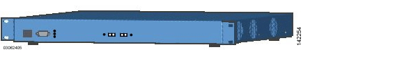
Figure 1-5 shows the Cisco 4100 Series Wireless LAN Controller, which has two redundant front-panel SX/LC jacks. Note that the 1000BASE-SX circuits provides a 100/1000 Mbps wired connection to a network through an 850nM (SX) fiber-optic link using an LC physical connector.
Figure 1-5 4100 Series Controller
The Cisco 4100 Series Wireless LAN Controller can be factory-ordered with a VPN/Enhanced Security Module (Crypto Card) to support VPN, IPSec and other processor-intensive tasks, and contains two (Cisco 4100 Series Wireless LAN Controller) 1000BASE-SX network connectors that allow the Cisco 4100 Series Wireless LAN Controller to communicate with the network at Gigabit Ethernet speeds. The 1000BASE-SX network connectors provides 100/1000 Mbps wired connections to a network through 850nM (SX) fiber-optic links using LC physical connectors.
The two redundant Gigabit Ethernet connections on the Cisco 4100 Series Wireless LAN Controller allow the Cisco 4100 Series Wireless LAN Controller to bypass single network failures. At any given time one of the Cisco 4100 Series Wireless LAN Controller Gigabit Ethernet connections is active and the other is passive. Upon a network failure, the active connection becomes passive, and the passive connection becomes active.
Cisco 4400 Series Wireless LAN Controllers
Cisco 4400 Series Wireless LAN Controllers are part of the Cisco Wireless LAN Solution. Each Cisco 4400 Series Wireless LAN Controller controls up to 100 Cisco 1000 series lightweight access points, making it ideal for large-sized enterprises and large-density applications.
The 4402 Cisco 4400 Series Wireless LAN Controller has one set of two redundant front-panel SX/LC/T SFP modules (SFP transceiver, or Small Form-factor Plug-in), and the 4404 Cisco 4400 Series Wireless LAN Controller has two sets of two redundant front-panel SX/LC/T SFP modules:
•
•
•
The one or two sets of redundant Gigabit Ethernet connections on the Cisco 4400 Series Wireless LAN Controller allow the Cisco 4400 Series Wireless LAN Controller to bypass single network failures. At any given time one of the Cisco 4400 Series Wireless LAN Controller Gigabit Ethernet connections is active and the other is passive. Upon a network failure, the active connection becomes passive, and the passive connection becomes active.
The Cisco 4400 Series Wireless LAN Controller can be equipped with one or two Cisco 4400 series power supplies. When the Cisco Wireless LAN Controller is equipped with two Cisco 4400 series power supplies, the power supplies are redundant and either power supply can continue to power the Cisco 4400 Series Wireless LAN Controller if the other power supply fails.
One Cisco 4400 series power supply is included standard with the Cisco Wireless LAN Controller, and is installed in Slot 1 at the factory. For redundancy, a second Cisco 4400 series power supply can be ordered from the factory and may be installed in Slot 2. The same power supply also fits in Slot 1 and can be used to replace a failed power supply in the field.
Cisco 2000 Series Wireless LAN Controller Model Numbers
Cisco 2000 Series Wireless LAN Controller model number is as follows:
•
Note
Cisco 4100 Series Wireless LAN Controller Model Numbers
Cisco 4100 Series Wireless LAN Controller model numbers are as follows:
•
•
•
Note
The following upgrade module is also available:
•
Cisco 4400 Series Wireless LAN Controller Model Numbers
Cisco 4400 Series Wireless LAN Controller model numbers are as follows:
•
•
•
•
Note
The 4402 Cisco 4400 Series Wireless LAN Controller uses one set of two redundant front-panel SX/LC/T SFP modules (SFP transceiver, or Small Form-factor Plug-in), and the 4404 Cisco 4400 Series Wireless LAN Controller uses two sets of two redundant front-panel SX/LC/T SFP modules:
•
•
•
The following power supply module is also available:
•
Distribution System Ports
A Distribution System (DS) port is a physical port through which controller talks to access points across the network. DS ports are where packets are exchanged between the Cisco Wireless LAN Solution wireless LANs and the rest of the network.
Note
As described in the "Layer 2 and Layer 3 LWAPP Operation" section, when the LWAPP communications are set to Layer 2 (same subnet) operation, the Distribution System must have one management interface to control all inter-controller and all controller-to-access point communications, regardless of the number of physical Distribution System ports.
Also as described in the "Layer 2 and Layer 3 LWAPP Operation" section, when the LWAPP communications are set to Layer 3 (different subnet) operation, the Distribution System must have one management interface to control all inter-controller communications, and must have one AP-Manager interface to control all controller-to-access point communications, regardless of the number of physical Distribution System ports.
Each physical Distribution System port can also have between one and 512 operator-defined interfaces assigned to it. Each operator-defined interface is individually configured, and allows VLAN communications to exist on the distribution system port(s).
About the Management Interface
The logical Management Interface controls Layer 2 communications between Cisco Wireless LAN Controllers and Cisco 1000 series lightweight access points.
Note
The Management Interface is assigned to one physical port through which it communicates with other network devices and other access points. However, the Management Interface can also communicate through all other physical ports except the service port as follows:
•
•
Note
Note
The Management Interface uses the burned-in Cisco Wireless LAN Controller Distribution System MAC address, and must be configured for the following:
•
•
•
•
•
Refer to the "Verifying and Changing the Management Interfaces" section on page 7-2 for configuration instructions.
AP-Manager Interface
The logical AP-Manager Interface controls Layer 3 communications between Cisco Wireless LAN Controller and lightweight access points.
The AP-Manager Interface is assigned to one physical port and can be on the same subnet and physical port as the management interface. The AP-Manager Interface can communicate through any physical port except the service port as follows:
•
•
Note
The AP-Manager Interface must be configured for the following:
•
•
•
•
•
Refer to the "Creating and Assigning the AP-Manager Interface" section on page 7-3 for configuration instructions.
Operator-Defined Interfaces
Each Cisco Wireless LAN Controller can support up to 512 Operator-Defined Interfaces. Each Operator-Defined Interface controls VLAN and other communications between Cisco Wireless LAN Controllers and all other network devices connected to an individual physical port. Between one and 512 Operator-Defined Interfaces can be assigned to wireless LANs, physical distribution system ports, the Layer 2 management interface, and the Layer 3 AP-Manager interface.
Note
Note
Each Operator-Defined Interface must be configured for the following:
•
•
•
•
•
Refer to the "Creating, Assigning, and Deleting Operator-Defined Interfaces" section on page 7-3 for configuration instructions.
Virtual Interface
The Virtual Interface controls Layer 3 Security and Mobility manager communications for Cisco Wireless LAN Controllers. It maintains the DNS Gateway hostname used by Layer 3 Security and Mobility managers to verify the source of certificates when Layer 3 Web Auth is enabled.
The Virtual Interface must be configured for the following:
•
•
Refer to the "Verifying and Changing the Virtual Interface" section on page 7-4 for configuration instructions.
Service Port
The physical Service port on the Cisco Wireless LAN Controller is a 10/100BASE-T Ethernet port dedicated to operating system device service, and was formerly known as the Management port. The Service Port is controlled by the service-port interface.
The Service Port is configured with an IP Address, subnet mask, and IP assignment protocol different from the management interface. This allows the operator to manage the Cisco Wireless LAN Controller directly or through a dedicated operating system service network, such as 10.1.2.x, which can ensure operating system device service access during network downtime.
Cisco WLAN Solution created the Service port to remove the Cisco Wireless LAN Controller device service from the network data stream to improve security and to provide a more secure service connection.
Note that you cannot assign a Gateway to the Service port, so the port is not routable. However, you can set up dedicated routes to network management devices.
Also note that the Service Port is not auto-sensing: you must use the correct straight-through or crossover Ethernet cable to communicate with the Service Port.
Refer to the "Configuring the Service Port" section on page 4-9 for information on how to configure the Service Port.
Service-Port Interface
The Service-Port Interface controls communications through the dedicated Cisco Wireless LAN Controller service port. See the "Service Port" section for more information about the service port.
Note
The Service-Port Interface uses the burned-in Cisco Wireless LAN Controller Service Port MAC address, and must be configured for the following:
•
•
Refer to the "Configuring the Service Port" section on page 4-9 for configuration instructions.
Startup Wizard
When an Cisco Wireless LAN Controller is powered up with a new factory operating system software load or after being reset to factory defaults, the bootup script runs the Startup Wizard, which prompts the installer for initial configuration. The Startup Wizard:
•
•
•
•
•
•
•
•
•
•
•
•
•
•
To use the Startup Wizard, refer to the "Using the Configuration Wizard" section on page 4-2.
Cisco Wireless LAN Controller Memory
The Cisco Wireless LAN Controller contain two kinds of memory: volatile RAM, which holds the current, active Cisco Wireless LAN Controller configuration, and NVRAM (non-volatile RAM), which holds the reboot configuration. When you are configuring the operating system in a Cisco Wireless LAN Controller, you are modifying volatile RAM; you must save the configuration from the volatile RAM to the NVRAM to ensure that the Cisco Wireless LAN Controller reboots in the current configuration.
Knowing which memory you are modifying is important when you are:
•
•
Cisco Wireless LAN Controller Failover Protection
Each Cisco Wireless LAN Controller has a defined number of communication ports for Cisco 1000 series lightweight access points. This means that when multiple controllers with unused access point ports are deployed on the same network, if one controller fails, the dropped access points automatically poll for unused controller ports and associate with them.
During installation, Cisco recommends that you connect all lightweight access points to a dedicated controller, and configure each lightweight access point for final operation. This step configures each lightweight access point for a primary, secondary, and tertiary controller, and allows it to store the configured WLAN Solution Mobility Group information.
During failover recovery, the configured lightweight access points obtain an IP address from the local DHCP server (only in Layer 3 Operation), attempt to contact their primary, secondary, and tertiary controllers, and then attempt to contact the IP addresses of the other controllers in the Mobility group. This prevents the access points from spending time sending out blind polling messages, resulting in a faster recovery period.
In multiple-controller deployments, this means that if one controller fails, its dropped access points reboot and do the following under direction of the Radio Resource Management (RRM):
•
•
•
•
•
This means that when sufficient controllers are deployed, should one controller fail, active access point client sessions are momentarily dropped while the dropped access point associates with an unused port on another controller, allowing the client device to immediately reassociate and reauthenticate.
Cisco Wireless LAN Controller Automatic Time Setting
Each controller can have its time manually set or can be configured to obtain the current time from one or more Network Time Protocol (NTP) servers. Each NTP server IP address is added to the controller database. Each controller searches for an NTP server and obtains the current time upon reboot and at each user-defined polling interval (daily to weekly).
Cisco Wireless LAN Controller Time Zones
Each Cisco Wireless LAN Controller can have its time zone manually set or can be configured to obtain the current time from one or more Network Time Protocol (NTP) servers. Each NTP server IP address is added to the Cisco Wireless LAN Controller database. Each Cisco Wireless LAN Controller can search for an NTP server and obtain the current time zone upon reboot and at each user-defined (daily to weekly) polling interval.
Network Connections to Cisco Wireless LAN Controllers
Regardless of operating mode, all Cisco Wireless LAN Controllers use the network as an 802.11 Distribution System. Regardless of the Ethernet port type or speed, each Cisco Wireless LAN Controller monitors and communicates with its related Cisco Wireless LAN Controllers across the network. The following sections give details of these network connections:
•
•
•
Cisco 2000 Series Wireless LAN Controllers
Cisco 2000 Series Wireless LAN Controllers can communicate with the network through any one of its physical ports, as the logical management interface can be assigned to the one of the physical ports. The physical port description follows:
•
Figure 1-6 shows connections to the 2000 series controller.
Figure 1-6 Physical Network Connections to the 2000 Series Controller
Cisco 4100 Series Wireless LAN Controllers
Cisco 4100 Series Wireless LAN Controllers can communicate with the network through one or two physical ports, and the logical management interface can be assigned to the one or two physical ports. The physical port description follows:
•
Note
Figure 1-7 shows connections to the 4100 series controller.
Figure 1-7 Physical Network Connections to the 4100 Series Controller
Cisco 4400 Series Wireless LAN Controllers
Cisco 4400 Series Wireless LAN Controllers can communicate with the network through one or two pairs of physical ports, and the logical management interface can be assigned to the physical ports. The physical port descriptions follows:
•
–
–
–
•
–
–
–
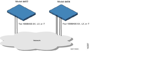
Figure 1-8 shows connections to the 4400 series controller.
Figure 1-8 Physical Network Connections to 4402 and 4404 Series Controllers
Cisco 4100 Series Wireless LAN Controller VPN/Enhanced Security Module
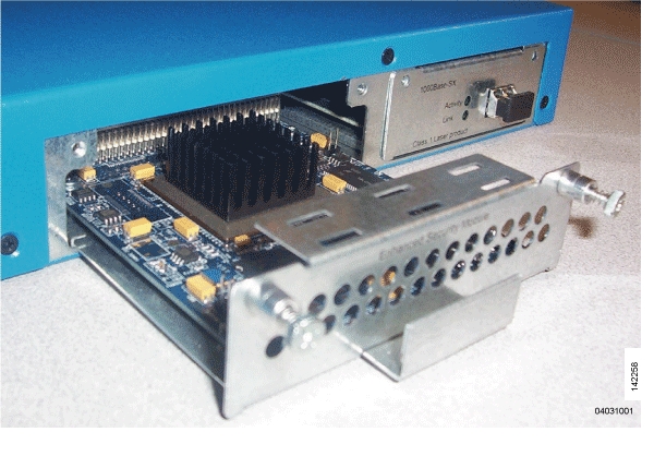
All Cisco 4100 Series Wireless LAN Controllers can be equipped with an optional VPN/Enhanced Security Module (AIR-VPN-4100), which slides into the rear panel of the Cisco 4100 Series Wireless LAN Controller. The VPN/Enhanced Security Module adds significant hardware encryption acceleration to the Cisco 4100 Series Wireless LAN Controller, which enables the following through the management interface:
•
•
•
Figure 1-9 shows the VPN/Enhanced Security Module sliding into the rear of a Cisco 4100 Series Wireless LAN Controller.
Figure 1-9 4100 Series Controller VPN/Enhanced Security Module Location
Lightweight Access Points
This section describes Cisco lightweight access points.
Cisco 1000 Series IEEE 802.11a/b/g Lightweight Access Points
The Cisco 1000 series lightweight access point is a part of the innovative Cisco Wireless LAN Solution (Cisco Wireless LAN Solution). When associated with controllers as described below, the Cisco 1000 series lightweight access point provides advanced 802.11a and/or 802.11b/g Access Point functions in a single aesthetically pleasing plenum-rated enclosure. Figure 1-10 shows the two types of Cisco 1000 Series IEEE 802.11a/b/g lightweight access point: without and with connectors for external antennas.
Figure 1-10 1000 Series Lightweight Access Points
The Cisco WLAN Solution also offers 802.11a/b/g Cisco 1030 Remote Edge Lightweight Access Points, which are Cisco 1000 series lightweight access points designed for remote deployment, Radio Resource Management (RRM) control via a WAN link, and which include connectors for external antennas.
The Cisco 1000 series lightweight access point is manufactured in a neutral color so it blends into most environments (but can be painted), contains pairs of high-gain internal antennas for unidirectional (180-degree) or omnidirectional (360-degree) coverage, and is plenum-rated for installations in hanging ceiling spaces.
In the Cisco Wireless LAN Solution, most of the processing responsibility is removed from traditional SOHO (small office, home office) access points and resides in the Cisco Wireless LAN Controller.
Cisco 1030 Remote Edge Lightweight Access Points
The only exception to the general rule of lightweight access points being continuously controlled by Cisco Wireless LAN Controllers is the Cisco 1030 IEEE 802.11a/b/g remote edge lightweight access point (Cisco 1030 remote edge lightweight access point). The Cisco 1030 remote edge lightweight access point is intended to be located at a remote site, initially configured by a Cisco Wireless LAN Controller, and normally controlled by a Cisco Wireless LAN Controller.
However, because the Cisco 1030 remote edge lightweight access point bridges the client data (compared with other Cisco 1000 series lightweight access points, which pass all client data through their respective Cisco Wireless LAN Controller), if the WAN link breaks between the Cisco 1030 remote edge lightweight access point and its Cisco Wireless LAN Controller, the Cisco 1030 remote edge lightweight access point continues transmitting wireless LAN 1 client data through other Cisco 1030 remote edge lightweight access points on its local subnet. However, it cannot take advantage of features accessed from the Cisco Wireless LAN Controller, such as establishing new VLANs, until communication is reestablished.
The Cisco 1030 remote edge lightweight access point includes the traditional SOHO (small office, home office) AP processing power, and thus can continue operating if the WAN link to its associated Cisco Wireless LAN Controller fails. Because it is configured by its associated Cisco Wireless LAN Controller, it has the same wireless LAN configuration as the rest of the Cisco Wireless LAN Solution. As long as it remains connected to its Cisco Wireless LAN Controller, it varies its transmit power and channel selection under control of the RRM, and performs the same rogue access point location as any other Cisco 1000 series lightweight access point.
Note that the Cisco 1030 remote edge lightweight access point can support multiple wireless LANs while it is connected to its Cisco Wireless LAN Controller. However, when it loses connection to its Cisco Wireless LAN Controller, it supports only one wireless LAN on its local subnet.
Figure 1-11 shows a typical Cisco 1030 remote edge lightweight access point configuration:
Figure 1-11 Typical 1030 Lightweight Access Point Configuration
Note that the Cisco 1030 remote edge lightweight access point must have a DHCP server available on its local subnet, so it can obtain an IP address upon reboot. Also note that the Cisco 1030 remote edge lightweight access points at each remote location must be on the same subnet to allow client roaming.
Cisco 1000 Series Lightweight Access Point Part Numbers
The Cisco 1000 series lightweight access point includes one 802.11a and one 802.11b/g radio. The Cisco 1000 series lightweight access point is available in the following configurations:
•
•
•
Refer to Appendix D, "Cisco WLAN Solution Supported Country Codes" for information on supported regulatory domains.
The Cisco 1000 series lightweight access point is shipped with a color-coordinated ceiling mount base and hanging-ceiling rail clips. You can also order projection- and flush-mount sheet metal wall mounting bracket kits. The base, clips, and optional brackets allow quick mounting to ceiling or wall.
The Cisco 1000 series lightweight access point can be powered by Power over Ethernet or by an external power supply. The external power supply model is:
•
The Single Inline PoE injector model is:
•
The projection and flush sheet metal wall mount bracket model is:
•
Cisco 1000 Series Lightweight Access Point External and Internal Antennas
The Cisco 1000 series lightweight access point enclosure contains one 802.11a or one 802.11b/g radio and four (two 802.11a and two 802.11b/g) high-gain antennas, which can be independently enabled or disabled to produce a 180-degree sectorized or 360-degree omnidirectional coverage area.
Note
Note that the wireless LAN operator can disable either one of each pair of the Cisco 1000 series lightweight access point internal antennas to produce a 180-degree sectorized coverage area. This feature can be useful, for instance, for outside-wall mounting locations where coverage is only desired inside the building, and in a back-to-back arrangement that can allow twice as many clients in a given area.
Refer to "Antenna Patterns for 1000 Series Access Points" for antenna patterns.
External Antenna Connectors
The AP1020 and AP1030 Cisco 1000 series lightweight access points have male reverse-polarity TNC jacks for installations requiring factory-supplied external directional or high-gain antennas. The external antenna option can create more flexibility in Cisco 1000 series lightweight access point antenna placement.
Note
Note that the 802.11b/g 2.4 GHz Left external antenna connector is associated with the internal Side A antenna, and that the 2.4 GHz Right external antenna connector is associated with the internal Side B antenna. When you have 802.11b/g diversity enabled, the Left external or Side A internal antennas are diverse from the Right external or Side B internal antennas.
Also note that the 802.11a 5 GHz Left external antenna connector is separate from the internal antennas, and adds diversity to the 802.11a transmit and receive path. Note that no external 802.11a antennas are certified in FCC-regulated areas, but external 802.11a antennas may be certified for use in other countries.
Antenna Sectorization
Note that the Cisco WLAN Solution supports Antenna Sectorization, which can be used to increase the number of clients and/or client throughput a given air space. Installers can mount two Cisco 1000 series lightweight access points back-to-back, and the Network operator can disable the second antenna in both access points to create a 360-degree coverage area with two sectors.
Installers can also mount Cisco 1000 series lightweight access points on the periphery of a building and disable the Side B internal antennas. This configuration can be used to supply service to the building interior without extending coverage to the parking lot, at the cost of eliminating the internal antenna diversity function.
Refer to Appendix E: Internal Antenna Patterns for information on the radiation patterns of internal antennas in 1000 series lightweight access points.
Cisco 1000 Series Lightweight Access Point LEDs
Each Cisco 1000 series lightweight access point is equipped with four LEDs across the top of the case. They can be viewed from nearly any angle. The LEDs indicate power and fault status, 2.4 GHz (802.11b/g) Cisco Radio activity, and 5 GHz (802.11a) Cisco Radio activity.
This LED display allows the wireless LAN manager to quickly monitor the Cisco 1000 series lightweight access point status. For more detailed troubleshooting instructions, refer to the Error Messages and Access Point LEDs appendix.
Cisco 1000 Series Lightweight Access Point Connectors
The AP1020 and AP1030 Cisco 1000 series lightweight access points have the following external connectors:
•
•
•
Note
The Cisco 1000 series lightweight access point communicates with a Cisco Wireless LAN Controller using standard CAT-5 (Category 5) or higher 10/100 Mbps twisted pair cable with RJ-45 connectors. Plug the CAT-5 cable into the RJ-45 jack on the side of the Cisco 1000 series lightweight access point.
Note that the Cisco 1000 series lightweight access point can receive power over the CAT-5 cable from network equipment. Refer to Power over Ethernet for more information about this option.
The Cisco 1000 series lightweight access point can be powered from an optional factory-supplied external AC-to-48 VDC power adapter. If you are powering the Cisco 1000 series lightweight access point using an external adapter, plug the adapter into the 48 VDC power jack on the side of the Cisco 1000 series lightweight access point.
The Cisco 1000 series lightweight access point includes two 802.11a and two 802.11b/g high-gain internal antennas, which provide omnidirectional coverage. However, some Cisco 1000 series lightweight access points can also use optional factory-supplied external high-gain and/or directional antennas. When you are using external antennas, plug them into the male reverse-polarity TNC jacks on the side of the AP1020 and AP1030 Cisco 1000 series lightweight access points.
Note
Cisco 1000 Series Lightweight Access Point Power Requirements
Each Cisco 1000 series lightweight access point requires a 48 VDC nominal (between 38 and 57 VDC) power source capable of providing 7 Watts. The polarity of the DC source does not matter because the Cisco 1000 series lightweight access point can use either a +48 VDC or a -48 VDC nominal source.
Cisco 1000 series lightweight access points can receive power from the external power supply (which draws power from a 110-220 VAC electrical outlet) plugged into the side of the access point case, or from Power over Ethernet.
Cisco 1000 Series Lightweight Access Point External Power Supply
The Cisco 1000 series lightweight access point can receive power from an external 110-220 VAC-to-48 VDC power supply or from Power over Ethernet equipment.
The external power supply (AIR-PWR-1000) plugs into a secure 110 through 220 VAC electrical outlet. The converter produces the required 48 VDC output for the Cisco 1000 series lightweight access point. The converter output feeds into the side of the Cisco 1000 series lightweight access point through a 48 VDC jack.
Note that the AIR-PWR-1000 external power supply can be ordered with country-specific electrical outlet power cords. Contact Cisco when ordering to receive the correct power cord.
Cisco 1000 Series Lightweight Access Point Mounting Options
Cisco 1000 Series Lightweight Access Point Mounting OptionsRefer to the Internal-Antenna AP1010 Cisco 1000 Series IEEE 802.11a/b/g Lightweight Access Point Quick Start Guide or the External-Antenna AP1020 and AP1030 Cisco 1000 Series IEEE 802.11a/b/g Lightweight Access Point Quick Start Guide for the Cisco 1000 series lightweight access point mounting options.
Cisco 1000 Series Lightweight Access Point Physical Security
The side of the Cisco 1000 series lightweight access point housing includes a slot for a Kensington MicroSaver Security Cable. Refer to the Kensington website for more information about their security products, or to the Internal-Antenna AP1010 Cisco 1000 Series IEEE 802.11a/b/g Lightweight Access Point Quick Start Guide or External-Antenna AP1020 and AP1030 Cisco 1000 Series IEEE 802.11a/b/g Lightweight Access Point Quick Start Guide for installation instructions.
Cisco 1000 Series Lightweight Access Point Monitor Mode
The Cisco 1000 series lightweight access points and Cisco Wireless LAN Controllers can perform rogue access point detection and containment while providing regular service. The rogue access point detection is performed across all 801.11 channels, regardless of the Country Code selected. (Refer to Appendix D, "Cisco WLAN Solution Supported Country Codes" for more details).
However, if the administrator would prefer to dedicate specific Cisco 1000 series lightweight access points to rogue access point detection and containment, the Monitor mode should be enabled for individual Cisco 1000 series lightweight access points.
The Monitor function is set for all 802.11 Cisco Radios on a per-access point basis using any of the Cisco Wireless LAN Controller user interfaces.
Using the DNS for Controller Discovery
In Cisco Wireless LAN Solution software releases 3.0 and later, access points can discover controllers through your domain name server (DNS). To use this feature you configure your DNS to return controller IP addresses in response to CISCO-LWAPP-CONTROLLER@localdomain. When an access point receives an IP address and DNS information from a DHCP server, it contacts the DNS to resolve CISCO-LWAPP-CONTROLLER@localdomain. When the DNS sends a list of controller IP addresses, the access point sends discovery requests to the controllers.
Autonomous Access Points Converted to Lightweight Mode
You can use an upgrade conversion tool to convert autonomous Cisco Aironet 1130AG, 1200, and 1240AG Series Access Points to lightweight mode. When you upgrade one of these access points to lightweight mode, the access point communicates with a wireless LAN controller and receives a configuration and software image from the controller.
Refer to these documents for complete instructions on upgrading an autonomous access point to lightweight mode:
•
•
Guidelines for Using Access Points Converted to Lightweight Mode
Keep these guidelines in mind when you use autonomous access points that have been converted to lightweight mode:
•
•
•
•
•
Reverting from Lightweight Mode to Autonomous Mode
After you use the upgrade tool to convert an autonomous access point to lightweight mode, you can convert the access point from a lightweight unit back to an autonomous unit by loading a Cisco IOS release that supports autonomous mode (Cisco IOS release 12.3(7)JA or earlier). If the access point is associated to a controller, you can use the controller to load the Cisco IOS release. If the access point is not associated to a controller, you can load the Cisco IOS release using TFTP. In either method, the access point must be able to access a TFTP server that contains the Cisco IOS release to be loaded.
Using a Controller to Return to a Previous Release
Follow these steps to revert from lightweight mode to autonomous mode using a wireless LAN controller:
Step 1
Step 2
config ap tftp-downgrade tftp-server-ip-address filename access-point-name
Step 3
Using the MODE Button and a TFTP Server to Return to a Previous Release
Follow these steps to revert from lightweight mode to autonomous mode by using the access point MODE (reset) button to load a Cisco IOS release from a TFTP server:
Step 1
Step 2
Step 3
Step 4
Step 5
Step 6
Note
Step 7
Step 8
Step 9
Controllers Accept SSCs from Access Points Converted to Lightweight Mode
The lightweight access point protocol (LWAPP) secures the control communication between the access point and controller by means of a secure key distribution requiring X.509 certificates on both the access point and controller. LWAPP relies on a priori provisioning of the X.509 certificates. Factory installed certificates are referenced by the term MIC, which is an acronym for manufacturing-installed certificate. Cisco Aironet access points shipped before July 18, 2005 do not have a MIC, so these access points create a self-signed certificate (SSC) when upgraded to operate in lightweight mode. Controllers are programmed to accept SSCs for authentication of specific access points.
Using DHCP Option 43
Cisco 1000 series access points use a string format for DHCP option 43, whereas Cisco Aironet access points use the type-length-value (TLV) format for DHCP option 43. DHCP servers must be programmed to return the option based on the access point's DHCP Vendor Class Identifier (VCI) string (DHCP Option 60). Table 1-2 lists the VCI strings for Cisco access points capable of operating in lightweight mode.
This is the format of the TLV block:
•
•
•
Refer to the the product documentation for your DHCP server for instructions on configuring DHCP Option 43. The Application Note: Upgrading Autonomous Cisco Aironet Access Points To Lightweight Mode contains example steps for configuring option 43 on a DHCP server.
Using a Controller to Send Debug Commands to Access Points Converted to Lightweight Mode
Enter this command to enable the controller to send debug commands to an access point converted to lightweight mode:
config ap remote-debug [enable | disable | exc_command] access-point-name
When this feature is enabled, the controller sends debug commands to the converted access point as character strings. You can send any debug command supported by Cisco Aironet access points that run Cisco IOS software in lightweight mode.
Converted Access Points Send Crash Information to Controller
When a converted access point unexpectedly reboots, the access point stores a crash file on its local flash memory at the time of crash. After the unit reboots, it sends the reason for the reboot to the controller. If the unit rebooted because of a crash, the controller pulls up the crash file using existing LWAPP messages and stores it in the controller flash memory. The crash info copy is removed from the access point flash memory when the controller pulls it from the access point.
Converted Access Points Send Radio Core Dumps to Controller
When a radio module in a converted access point generates a core dump, the access point stores the core dump file of the radio on its local flash memory at the time of the radio crash. It sends a notification message to the controller indicating which radio generated a core dump file. The controller sends a trap alerting the network administrator, and the administrator can retrieve the radio core file from the access point.
On the controller CLI, enter this command to pull the core file from the access point:
config ap get-radio-core-dump slot ap-name
For slot, enter the radio interface number on the access point.
The retrieved core file is stored in the controller flash and can subsequently be uploaded through TFTP to an external server for analysis. The core file is removed from the access point flash memory when the controller pulls it from the access point.
Enabling Memory Core Dumps from Converted Access Points
By default, access points converted to lightweight mode do not send memory core dumps to the controller. To enable this feature, enter this command:
config ap core-dump enable tftp-server-ip-address filename {compress | uncompress} {ap-name | all}
•
•
•
•
Display of MAC Addresses for Converted Access Points
There are some differences in the way that controllers display the MAC addresses of converted access points on information pages in the controller GUI:
•
•
•
Disabling the Reset Button on Access Points Converted to Lightweight Mode
You can disable the reset button on access points converted to lightweight mode. The reset button is labeled MODE on the outside of the access point.
Use this command to disable or enable the reset button on one or all converted access points associated to a controller:
config ap reset-button {enable | disable} {ap-name | all}
The reset button on converted access points is enabled by default.
Configuring a Static IP Address on an Access Point Converted to Lightweight Mode
After an access point converted to lightweight mode associates to a controller, enter this command to configure a static IP address on the access point:
config ap static-ip enable ap-name ip-address mask gateway
Rogue Access Points
Because they are inexpensive and readily available, employees sometimes plug unauthorized rogue access points into existing LANs and build ad hoc wireless networks without IT department knowledge or consent.
These rogue access points can be a serious breach of network security because they can be plugged into a network port behind the corporate firewall. Because employees generally do not enable any security settings on the rogue access point, it is easy for unauthorized users to use the access point to intercept network traffic and hijack client sessions. Even more alarming, wireless users and war chalkers frequently publish unsecure access point locations, increasing the odds of having the enterprise security breached.
Rather than using a person with a scanner to manually detect rogue access point, the Cisco Wireless LAN Solution automatically collects information on rogue access point detected by its managed access points, by MAC and IP Address, and allows the system operator to locate, tag and monitor them as described in the "Detecting and Locating Rogue Access Points" section on page 9-14. The operating system can also be used to discourage rogue access point clients by sending them deauthenticate and disassociate messages from one to four Cisco 1000 series lightweight access points. Finally, the operating system can be used to automatically discourage all clients attempting to authenticate with all rogue access point on the enterprise subnet. Because this real-time detection is automated, it saves labor costs used for detecting and monitoring rogue access point while vastly improving LAN security. Note that peer-to-peer, or ad-hoc, clients can also be considered rogue access points.
Rogue Access Point Location, Tagging, and Containment
This built-in detection, tagging, monitoring, and containment capability allows system administrators to take required actions:
•
•
•
•
•
•
–
–
–
–
Rogue Detector mode detects whether or not a rogue access point is on a trusted network. It does not provide RF service of any kind, but rather receives periodic rogue access point reports from the Cisco Wireless LAN Controller, and sniffs all ARP packets. If it finds a match between an ARP request and a MAC address it receives from the Cisco Wireless LAN Controller, it generates a rogue access point alert to the Cisco Wireless LAN Controller.
To facilitate automated rogue access point detection in a crowded RF space, Cisco 1000 series lightweight access points can be configured to operate in monitor mode, allowing monitoring without creating unnecessary interference.
Web User Interface and the CLI
This section describes the controller GUI and CLI.
Web User Interface
The Web User Interface is built into each Cisco Wireless LAN Controller. The Web User Interface allows up to five users to simultaneously browse into the built-in Cisco Wireless LAN Controller http or https (http + SSL) Web server, configure parameters, and monitor operational status for the Cisco Wireless LAN Controller and its associated Access Points.
Note
Because the Web User Interface works with one Cisco Wireless LAN Controller at a time, the Web User Interface is especially useful when you wish to configure or monitor a single Cisco Wireless LAN Controller and its associated Cisco 1000 series lightweight access points.
Refer to the "Using the Web-Browser Interface" section for more information on the Web User Interface.
Command Line Interface
The Cisco Wireless LAN Solution command line interface (CLI) is built into each Cisco Wireless LAN Controller. The CLI allows operators to use a VT-100 emulator to locally or remotely configure, monitor and control individual Cisco Wireless LAN Controllers, and to access extensive debugging capabilities.
Because the CLI works with one Cisco Wireless LAN Controller at a time, the command line interface is especially useful when you wish to configure or monitor a single Cisco Wireless LAN Controller.
The Cisco Wireless LAN Controller and its associated Cisco 1000 series lightweight access points can be configured and monitored using the command line interface (CLI), which consists of a simple text-based, tree-structured interface that allows up to five users with Telnet-capable terminal emulators to simultaneously configure and monitor all aspects of the Cisco Wireless LAN Controller and associated Cisco 1000 series lightweight access points.
Refer to "Using the CLI" section and the Cisco Wireless LAN Solution CLI Reference for more information.
Cisco Wireless Control System
The Cisco Wireless Control System (Cisco WCS) is the Cisco Wireless LAN Solution network management tool that adds to the capabilities of the Web User interface and the CLI, moving from individual controllers to a network of controllers. WCS runs on Windows 2000, Windows 2003, and Red Hat Enterprise Linux ES servers.
The Cisco WCS includes the same configuration, performance monitoring, security, fault management, and accounting options used at the Cisco Wireless LAN Controller level, but adds a graphical view of multiple controllers and managed access points.
The Cisco WCS is offered in two versions which support different feature levels:
•
•
Table 1-3 lists these features.
The Cisco Wireless Control System runs on Windows 2000 or 2003 and Red Hat Enterprise Linux ES servers. The Windows Cisco WCS can run as a normal Windows application, or can be installed as a service, which runs continuously and resumes running after a reboot. The Linux Cisco WCS always runs as a normal Linux application.
The WCS User Interface allows Cisco WCS operators to control all permitted Cisco WLAN Solution configuration, monitoring, and control functions through Internet Explorer 6.0 on a Windows workstation (or other) web browser window. The Cisco WCS operator permissions are defined by the Cisco WCS administrator in the Cisco WCS User Interface using the Cisco WCS User Interface Admin tab, which allows the Cisco WCS administrator to administer user accounts and schedule periodic maintenance tasks.
Cisco WCS simplifies Cisco Wireless LAN Controller configuring and monitoring while decreasing data entry errors with the Cisco WCS Cisco Wireless LAN Controller Autodiscovery algorithm. The Cisco WCS uses industry-standard SNMP protocol to communicate with Cisco Wireless LAN Controllers.
The Cisco WCS also includes the Floor Plan Editor, which allows you to vectorize bitmapped campus, floor plan, and outdoor area maps, add and change wall types, and import the resulting vector wall format maps into the Cisco WCS database. The vector files allow the Cisco WCS RF Prediction Tool to make much better RF predictions based on more accurate wall and window RF attenuation values. Refer to the "Using Maps" section on page 9-4 for more information on maps in WCS.
Cisco WCS Base
The Cisco WCS Base version supports wireless client data access, rogue access point detection and containment functions, Cisco WLAN Solution monitoring and control, and includes graphical views of the following:
•
•
•
•
–
–
–
–
•
–
–
–
–
–
–
–
•
•
•
Cisco WCS Location
In addition to the graphical representations listed in the "Cisco WCS Base" section, Cisco WCS Location adds the following enhancements:
•
•
•
•
Cisco WCS User Interface
The Cisco WCS User Interface interface allows the network operator to create and configure Cisco Wireless LAN Solution coverage area layouts, configure system operating parameters, monitor real-time Cisco Wireless LAN Solution operation, and perform troubleshooting tasks using a standard HTTP or HTTPS web browser window. The Cisco WCS User Interface interface also allows a Cisco WCS administrator to create, modify and delete user accounts, change passwords, assign permissions, and schedule periodic maintenance tasks.
Cisco recommends Internet Explorer 6.0 or later on a Windows workstation web browser for full access to the Cisco WCS functionality.
The HTTPS (SSL over HTTP) interface is enabled by default, and the HTTP interface can be manually activated in the CLI, the GUI, and the WCS User Interface.
The Cisco WCS administrator creates new usernames passwords and assigns them to predefined permissions groups.
Cisco WCS User Interface operators perform their tasks as described in Chapter 9, "Using Cisco WCS."
Floor Plan Editor
Cisco WCS includes the Floor Plan Editor, which converts architectural, mechanical and technical drawings, graphics, maps and other types of line artwork from raster bitmaps to wall (vector) formats. Operators can use scanners to digitize paper drawings into supported file formats for import into Cisco WCS. The Floor Plan Editor automatically recognizes and represents the data in a wall format which can then be imported into your Cisco WCS program.
Because of its ability to create smooth straight, angled, and semi-angled outlines, the Floor Plan Editor is used to convert floor plan maps, define the wall characteristics, and import the resulting vector wall format maps into the Cisco WCS database. The vector files allow the Cisco WCS RF Prediction Tool to make much better RF predictions based on Cisco 1000 series lightweight access point signal strength, and accurate wall, window and cubicle RF attenuation.
Otherwise, you may want to save raster images in .BMP, .TIFF, .JPEG, or .PNG raster formats. Note that you can also edit existing vector map files.
The output wall files can be saved in vector (Cisco WLAN Solution wall format) for importing directly into the Cisco WCS database. The output wall files can also be saved in the following formats, but Cisco WCS does not recognize these file types: .DXF (AutoCAD), .AI (Adobe Illustrator), .EMF (enhanced metafile), .WMF (Windows metafile), and .TXT (ASCII XY).
Note that there are no restrictions on the input or output image size.
Tip
Tip
Refer to the "Using Maps" section on page 9-4 for information on using maps in WCS.
Cisco WCS Cisco Wireless LAN Controller Autodiscovery
Manually adding Cisco Wireless LAN Controller data to a management database can be time consuming, and is susceptible to data entry errors. Cisco WCS includes a built-in Cisco Wireless LAN Controller configuration upload function that speeds up database creation while eliminating errors.
Cisco Wireless LAN Controller Autodiscovery is limited to the Mobility Group subnets defined by the Cisco Wireless LAN Solution operator.
Cisco Wireless LAN Controller Autodiscovery allows operators to search for a single Cisco Wireless LAN Controller by IP Address. The Autodiscovery function finds the Cisco Wireless LAN Controller on the network with the specified IP Address, and automatically enters the discovered Cisco Wireless LAN Controller information into the Cisco WCS database.
As lightweight access points associate with controller, the controller immediately transmits the access point information to Cisco WCS, which automatically adds the access point to the Cisco WCS database.
After the Cisco 1000 series lightweight access point information is in the Cisco WCS database, operators can add the Cisco 1000 series lightweight access point to the appropriate spot on a Cisco WCS User Interface map, so the topological map of the air space remains current.
Cisco WCS Alarm Email Notification
Cisco WCS includes a built-in email notification function, which can notify network operators when Critical alarms occur.
Refer to the Cisco WCS Monitor All Alarms > Email Notification page to view the current alarm notification settings.
Cisco WCS Location Calibration
Cisco WCS includes a calibration tool which allows Cisco Wireless LAN Solution operators to accurately measure actual signal strength and attenuation in RF coverage areas, which creates an accurate calibration model in the Cisco WCS database. This calibration model allows more precise client and rogue access point location after calibration is completed. To save effort, the calibration model can also be reused for areas with an identical Cisco 1000 series lightweight access point layout and identical wall layout.
The calibration tool is used much like a site survey tool, and allows a technician to take a Cisco WCS-equipped laptop to multiple locations on a floor or outdoor area and measure actual signal strength at selected locations on the floor or outdoor area map. The technician then uses the calibration tool in Cisco WCS to process the collected data points for the floor or outdoor area.
Refer to the Cisco WCS Monitor RF Calibration Models page to view the current calibration models.
Cisco 2700 Series Location Appliances
The Cisco 2700 Series Location Appliance (location appliance) enhances the high-accuracy built-in Cisco WCS Location abilities by computing, collecting and storing historical location data, which can be displayed in Cisco WCS. In this role, the location appliance acts as a server to one or more Cisco WCS Servers, collecting, storing, and passing on data from its associated Cisco Wireless LAN Controllers.
After a quick command-line interface (CLI) configuration, the remaining location appliance configuration can be completed using the Cisco WCS interface.
After it is configured, each location appliance communicates directly with its associated Cisco Wireless LAN Controllers to collect operator-defined location data. The associated Cisco WCS Server operators can then communicate with each location appliance to transfer and display selected data.
The location appliance can be backed up to any Cisco WCS Server into an operator-defined FTP folder, and the location appliance can be restored from that Cisco WCS Server at any time and at defined intervals. Also, the location appliance database can be synchronized with the Cisco WCS Server database at any time.
Operators can use the location appliance features and download new application code to all associated location appliances from any Cisco WCS Server.
When Cisco WCS is enhanced with a location appliance, Cisco WCS can display historical location data for up to 1,500 Laptop Clients, Palmtop Clients, VoIP Telephone Clients, RFID (Radio Frequency IDentifier) Asset Tags, Rogue Access Points, and Rogue Access Point Clients for each location appliance in the Cisco Wireless LAN Solution.
Operators can configure location appliances to collect data for Cisco Wireless LAN Solution clients, rogue access points and clients, RFID Asset Tags, and statistics at separate operator-defined intervals.
The location appliance uses two redundant back-panel 10/100/1000BASE-T ports to connect to one or two network segments. It also features a back-panel power cord and front-panel ON/OFF switch. The location appliance includes a back-panel DB-9 console port for initial configuration using a CLI console.
Note that each location appliance can be installed in any NOC (Network Operations Center) or wiring closet from which it can communicate with its associated Cisco WCS Server(s) and Cisco Wireless LAN Controllers.
![]()
![]()
![]()
![]()
![]()
![]()
![]()
![]()
Posted: Thu Sep 15 09:11:01 PDT 2005
All contents are Copyright © 1992--2005 Cisco Systems, Inc. All rights reserved.
Important Notices and Privacy Statement.