|
|

Table Of Contents
Single Point of Configuration Policy Manager Solutions
Converting a Cisco WLAN Solution from Layer 2 to Layer 3 Mode
Using the Web User Interface to Convert from Layer 2 to Layer 3 Mode
Using the Cisco WCS User Interface to Convert from Layer 2 to Layer 3 Mode
Converting a Cisco WLAN Solution from Layer 3 to Layer 2 Mode
Using the Web User Interface to Convert from Layer 3 to Layer 2 Mode
Using the Cisco WCS User Interface to Convert from Layer 3 to Layer 2 Mode
Configuring a Firewall for Cisco WCS
Configuring the System for SpectraLink NetLink Telephones
Using the Controller CLI to Enable Long Preambles
Using the Controller GUI to Enable Long Preambles
Using WCS to Enable Long Preambles
Using Management over Wireless
Using the Controller CLI to Enable Management over Wireless
Using the the Controller GUI to Enable Management over Wireless
Using the Controller CLI to Configure DHCP
Using the Controller GUI to Configure DHCP
Customizing the Web Auth Login Screen
Customizing Web Auth Operation
Example: Sample Customized Web Auth Login Page
Configuring Identity Networking
RADIUS Attributes Used in Identity Networking
Solutions
This chapter describes application-specific solutions for wireless LANs. Solutions are described in these sections:
•
Cisco WLAN Solution Security
•
•
•
•
•
•
•
Cisco WLAN Solution Security
Cisco WLAN Solution Security includes the following sections:
•
•
•
Security Overview
The Cisco WLAN Solution Security solution bundles potentially complicated Layer 1, Layer 2, and Layer 3 802.11 Access Point security components into a simple policy manager that customizes system-wide security policies on a per-WLAN basis. The Cisco WLAN Solution Security solution provides simple, unified, and systematic security management tools.
One of the biggest hurdles to WLAN deployment in the enterprise is WEP encryption, which is weak standalone encryption method. A newer problem is the availability of low-cost access points, which can be connected to the enterprise network and used to mount man-in-the-middle and denial-of-service attacks. Also, the complexity of add-on security solutions has prevented many IT managers from embracing the benefits of the latest advances in WLAN security.
Layer 1 Solutions
The Cisco WLAN Solution Operating System Security solution ensures that all clients gain access within an operator-set number of attempts. Should a client fail to gain access within that limit, it is automatically excluded (blocked from access) until the operator-set timer expires. The Operating System can also disable SSID broadcasts on a per-WLAN basis.
Layer 2 Solutions
If a higher level of security and encryption is required, the network administrator can also implement industry-standard security solutions, such as: 802.1X dynamic keys with EAP (extensible authentication protocol), or WPA (Wi-Fi protected access) dynamic keys. The Cisco WLAN Solution WPA implementation includes AES (advanced encryption standard), TKIP + Michael (temporal key integrity protocol + message integrity code checksum) dynamic keys, or WEP (Wired Equivalent Privacy) static keys. Disabling is also used to automatically block Layer 2 access after an operator-set number of failed authentication attempts.
Regardless of the wireless security solution selected, all Layer 2 wired communications between Cisco Wireless LAN Controllers and Cisco 1000 Series lightweight access points are secured by passing data through LWAPP tunnels.
Layer 3 Solutions
The WEP problem can be further solved using industry-standard Layer 3 security solutions, such as VPNs (virtual private networks), L2TP (Layer Two Tunneling Protocol), and IPSec (IP security) protocols. The Cisco WLAN Solution L2TP implementation includes IPsec, and the IPSec implementation includes IKE (internet key exchange), DH (Diffie-Hellman) groups, and three optional levels of encryption: DES (ANSI X.3.92 data encryption standard), 3DES (ANSI X9.52-1998 data encryption standard), or AES/CBC (advanced encryption standard/cipher block chaining). Disabling is also used to automatically block Layer 3 access after an operator-set number of failed authentication attempts.
The Cisco WLAN Solution IPSec implementation also includes industry-standard authentication using: MD5 (message digest algorithm), or SHA-1 (secure hash algorithm-1).
The Cisco WLAN Solution supports local and RADIUS MAC (media access control) filtering. This filtering is best suited to smaller client groups with a known list of 802.11 access card MAC addresses.
Finally, the Cisco WLAN Solution supports local and RADIUS user/password authentication. This authentication is best suited to small to medium client groups.
Single Point of Configuration Policy Manager Solutions
When the Cisco WLAN Solution is equipped with Cisco WCS, you can configure system-wide security policies on a per-WLAN basis. SOHO Access Points force you to individually configure security policies on each access point, or use a third-party appliance to configure security policies across multiple access points.
Because the Cisco WLAN Solution security policies can be applied across the whole system from the Cisco Wireless Control System, errors can be eliminated and the overall effort is greatly reduced.
Rogue Access Point Solutions
This section describes security solutions for rogue access points.
Rogue Access Point Challenges
Rogue access points can disrupt WLAN operations by hijacking legitimate clients and using plaintext or other denial-of-service or man-in-the-middle attacks. That is, a hacker can use a rogue access point to capture sensitive information, such as passwords and username. The hacker can then transmit a series of clear-to-send (CTS) frames, which mimics an access point informing a particular NIC to transmit and instructing all others to wait, which results in legitimate clients being unable to access the WLAN resources. WLAN service providers thus have a strong interest in banning rogue access points from the air space.
The Operating System Security solution uses the Radio Resource Management (RRM) function to continuously monitor all nearby access points, automatically discover rogue access points, and locate them as described in the "Tagging and Containing Rogue Access Points" section.
Tagging and Containing Rogue Access Points
When the Cisco WLAN Solution is monitored using WCS, WCS generates the flags as rogue access point traps, and displays the known rogue access points by MAC address. The operator can then display a map showing the location of the Cisco 1000 Series lightweight access points closest to each rogue access point, allowing Known or Acknowledged rogue access points (no further action), marking them as Alert rogue access points (watch for and notify when active), or marking them as Contained rogue access points (have between one and four Cisco 1000 Series lightweight access points discourage rogue access point clients by sending the clients deauthenticate and disassociate messages whenever they associate with the rogue access point).
When the Cisco WLAN Solution is monitored using a GUI or a CLI, the interface displays the known rogue access points by MAC address. The operator then has the option of marking them as Known or Acknowledged rogue access points (no further action), marking them as Alert rogue access points (watch for and notify when active), or marking them as Contained rogue access points (have between one and four Cisco 1000 Series lightweight access points discourage rogue access point clients by sending the clients deauthenticate and disassociate messages whenever they associate with the rogue access point).
Integrated Security Solutions
•
•
•
•
•
•
•
Converting a Cisco WLAN Solution from Layer 2 to Layer 3 Mode
When you need to convert a Cisco WLAN Solution from Layer 2 to Layer 3 Mode, use one of the procedures in this section:
•
•
Using the Web User Interface to Convert from Layer 2 to Layer 3 Mode
Follow the steps in this section to convert a Cisco WLAN Solution from Layer 2 to Layer 3 LWAPP Transport Mode using the GUI on a wireless LAN controller.
Note
Note
Note
Step 1
Step 2
Note
Step 3
a.
b.
Step 4
Note
Step 5
a.
b.
Step 6
Step 7
Step 8
Step 9
•
•
•
•
•
•
•
•
Step 10
Step 11
a.
b.
c.
Step 12
Step 13
Step 14
You have completed the LWAPP Transport Mode conversion from Layer 2 to Layer 3. The ap-manager interface now controls all communications between Cisco Wireless LAN Controllers and Cisco 1000 Series lightweight access points on different subnets.
Using the Cisco WCS User Interface to Convert from Layer 2 to Layer 3 Mode
Follow the steps in this section to convert a Cisco WLAN Solution from Layer 2 to Layer 3 LWAPP Transport Mode using the GUI on the Cisco WCS.
Note
Note
Note
Step 1
Step 2
Note
Step 3
Step 4
If you do not complete this step, the Cisco 1000 Series lightweight access points might fail to associate with the controller after completing the conversion.
Step 5
a.
b.
c.
d.
Step 6
a.
b.
c.
–
–
–
–
–
–
–
–
–
d.
Step 7
Step 8
a.
b.
c.
d.
e.
Step 9
a.
b.
c.
Step 10
Step 11
Step 12
You have completed the LWAPP Transport Mode conversion from Layer 2 to Layer 3. The ap-manager interface now controls all communications between controllers and access points on different subnets.
Converting a Cisco WLAN Solution from Layer 3 to Layer 2 Mode
When you need to convert a Cisco WLAN Solution from Layer 2 to Layer 3 Mode, use one of the procedures in this section:
•
•
Using the Web User Interface to Convert from Layer 3 to Layer 2 Mode
Follow the steps in this section to convert a Cisco WLAN Solution from Layer 3 to Layer 2 LWAPP Transport Mode using the GUI on a wireless LAN controller.
Note
Step 1
Note
Step 2
Step 3
Step 4
Step 5
You have completed the LWAPP Transport Mode conversion from Layer 3 to Layer 2. The Operating System software now controls all communications between controllers and access points on the same subnet.
Using the Cisco WCS User Interface to Convert from Layer 3 to Layer 2 Mode
Using the Cisco WCS User InterfaceFollow the steps in this section to convert a Cisco WLAN Solution from Layer 3 to Layer 2 LWAPP Transport Mode using the GUI on the Cisco WCS.
Note
Step 1
Note
Step 2
a.
b.
c.
d.
Step 3
a.
b.
c.
Step 4
a.
b.
c.
You have completed the LWAPP Transport Mode conversion from Layer 3 to Layer 2. The Operating System software now controls all communications between controllers and lightweight access points on the same subnet.
Configuring a Firewall for Cisco WCS
When a Cisco WCS Server and a Cisco WCS User Interface are on different sides of a firewall, they cannot communicate unless the following ports on the firewall are opened to two-way traffic:
•
•
•
•
•
•
Open these ports to configure your firewall to allow communications between a Cisco WCS Server and a Cisco WCS User Interface.
Refer to the Cisco WCS Software Release Notes for any other ports that need to be opened for a Cisco WCS Server-to-Cisco WCS User Interface communications.
Configuring the System for SpectraLink NetLink Telephones
For best integration with the Cisco Wireless LAN Solution, SpectraLink NetLink Telephones require an extra Operating System configuration step: enable long preambles. The radio preamble (sometimes called a header) is a section of data at the head of a packet that contains information that wireless devices need when sending and receiving packets. Short preambles improve throughput performance, so they are enabled by default. However, some wireless devices, such as SpectraLink NetLink phones, require long preambles.
Use one of these methods to enable long preambles:
•
•
•
Using the Controller CLI to Enable Long Preambles
Use this procedure to use the controller CLI to enable long preambles to optimize the operation of SpectraLink NetLink phones on your wireless LAN.
Step 1
Step 2
Short Preamble mandatory....................... EnabledHowever, if the parameter shows that short preambles are disabled (which means that long preambles are enabled), the controller is already optimized for SpectraLink NetLink phones and you do not need to continue this procedure. This example shows that short preambles are disabled:
Short Preamble mandatory....................... DisabledStep 3
Step 4
Step 5
Step 6
The system has unsaved changes. Would you like to save them now? (y/n)The controller reboots.
Step 7
802.11b Network................................ EnabledShort Preamble mandatory....................... DisabledThese parameters show that the 802.11b/g network is enabled and that short preambles are disabled.
Using the Controller GUI to Enable Long Preambles
Use this procedure to use the controller GUI to enable long preambles to optimize the operation of SpectraLink NetLink phones on your wireless LAN.
Step 1
Step 2
Wireless > Global RF > 802.11b/g Network
If the Short Preamble Enabled box is checked, continue with this procedure. However, if the Short Preamble Enabled box is unchecked (which means that long preambles are enabled), the controller is already optimized for SpectraLink NetLink phones and you do not need to continue this procedure.
Step 3
Step 4
Note
Step 5
Configuration will be saved and switch will be rebooted. Click ok to confirm.The controller reboots.
Step 6
Wireless > Global RF > 802.11b/g Network
If the Short Preamble Enabled box is unchecked, the controller is optimized for SpectraLink NetLink phones.
Using WCS to Enable Long Preambles
Use this procedure to use WCS to enable long preambles to optimize the operation of SpectraLink NetLink phones on your wireless LAN.
Step 1
Step 2
Configuration > Configure Controllers > controller-ip-address > 802.11b/g > 802.11b/g Params
If the 802.11b/g Params page shows that short preambles are enabled, continue with this procedure. However, if short preambles are disabled (which means that long preambles are enabled), the controller is already optimized for SpectraLink NetLink phones and you do not need to continue this procedure.
Step 3
Step 4
Step 5
Step 6
Step 7
Please save configuration by clicking `Save Config' under `Switch Config' menu. Do you
want to continue Rebooting anyway?
The controller reboots. This will take some time, during which Cisco WCS loses its connection to the controller.
Note
Step 8
Monitor > Troubleshoot > Controller Status > controller-ip-address > 802.11b/g/Stats
On the Stats page, verify that Short Preamble Implemented is set to No, which indicates that this controller is optimized for SpectraLink NetLink Telephones.
Using Management over Wireless
The Cisco WLAN Solution Management over Wireless feature allows Cisco WLAN Solution operators to monitor and configure local controllers using a wireless client. This feature is supported for all management tasks except uploads to and downloads from (transfers to and from) the controller.
Before you can use the Management over Wireless feature, you must properly configure the controller using one of these sections:
•
•
Using the Controller CLI to Enable Management over Wireless
Step 1
Step 2
Step 3
Step 4
Using the the Controller GUI to Enable Management over Wireless
Using the Web User Interface
Step 1
Step 2
Step 3
Step 4
Step 5
Configuring DHCP
Follow the steps in one of these sections to configure your Wireless LAN to use a DHCP server:
•
•
Using the Controller CLI to Configure DHCP
Follow these steps to use the controller CLI to configure DHCP:
Using the Command Line Interface
Step 1
Step 2
•
•
•
In these commands, wlan-id = 1 through 16 and dhcp-ip-address = DHCP server IP Address.
Step 3
Step 4
Using the Controller GUI to Configure DHCP
Follow these steps to use the controller GUI to configure DHCP:
Step 1
Step 2
Step 3
Step 4
Step 5
Step 6
Step 7
Step 8
Step 9
Customizing the Web Auth Login Screen
When you use Web Authorization (Web Auth) to authenticate clients, you must define usernames and passwords for each client, and when clients attempt to join the wireless LAN, they must enter a valid username and password when prompted by a login window. These sections describe the default Web Auth operation and how to customize the Web Auth login screen.
•
•
Default Web Auth Operation
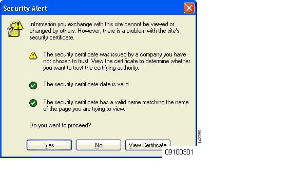
When Web Auth is enabled, clients might receive a web-browser security alert the first time that they attempt to access a URL. Figure 3-1 shows a typical security alert.
Figure 3-1 Typical Web-browser Security Alert
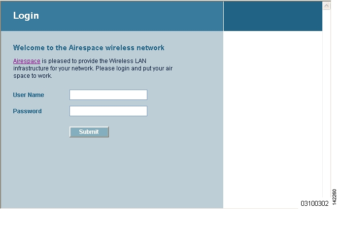
Figure 3-2 After the client user clicks Yes to proceed (or if the client's browser does not display a security alert) the Web Auth system redirects the client to a login window. Typical Web Auth Login Window
The client must respond with a username and password that you define using the Local Net Users > New Web User page, or using the config netuser add CLI command.
The default Web Auth login window contains Cisco WLAN Solution-specific text and a logo in four customizable areas:
•
•
•
•
The Customizing Web Auth Operation section explains how to customize the Cisco WLAN Solution logo, window title, message, and logo.
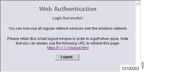
When the client enters a valid username and password, the Web Auth system displays a successful login window and redirects the authenticated client to the requested URL. Figure 3-3 shows a typical successful login window.
Figure 3-3 Typical Successful Login Window
The default login successful window contains a pointer to a virtual gateway address URL, redirect https://1.1.1.1/logout.html. You define this redirect through the Virtual Gateway IP Address parameter in the configuration wizard, the Virtual Gateway Address parameter on the Interfaces GUI page, or by entering the config interface create command in the CLI.
Customizing Web Auth Operation
This section explains how to customize Web Auth operation using the controller CLI. These sections describe the customization tasks:
•
•
•
•
Hiding and Restoring the Cisco WLAN Solution Logo
Use this command to delete or restore the Cisco WLAN Solution logo:
config custom-web weblogo {disable | enable}
Changing the Web Auth Window Title
Use this command to change the Web Auth window title:
config custom-web webtitle title
Use this command to reset the Web Auth window title back to the default setting:
clear webtitle
Changing the Web Message
Use this command to change the Web Auth window message:
config custom-web webmessage message
To reset the Web Auth window message to the Cisco WLAN Solution default ("Cisco WLAN Solution is pleased to provide the Wireless LAN infrastructure for your network. Please login and put your air space to work"), use this command:
clear webmessage
Changing the Logo
These sections explain how to change the logo on the right side of the Web Auth login window:
•
•
Preparing the TFTP Server
Follow thse steps to prepare a TFTP server to load the logo:
Step 1
•
•
Step 2
Note
Copying the Logo or Graphic to the TFTP Server
Follow these steps to copy the logo to the TFTP server:
Step 1
Step 2
Step 3
Downloading the Logo or Graphic
Follow these steps to download the image file to the controller:
Step 1
transfer download startMode........................................... TFTP Data Type...................................... Code TFTP Server IP................................. xxx.xxx.xxx.xxx TFTP Path...................................... <directory path> TFTP Filename..................................... <filename.jpg|.gif|.png>Are you sure you want to start? (y/n) nTransfer Canceled>Step 2
transfer download mode tftp
transfer download datatype image
transfer download serverip tftp-server-ip-address
transfer download filename {filename.gif | filename.jpg | filename.png}
transfer download path absolute-tftp-server-path-to-file
Note
Step 3
transfer download startMode........................................... TFTP Data Type...................................... Login Image TFTP Server IP................................. xxx.xxx.xxx.xxx TFTP Path...................................... <directory path> TFTP Filename.................................. <filename.jpg|.gif|.png>This may take some time. Are you sure you want to start? (y/n) yTFTP Image transfer starting.Image installed.Hiding the Logo
To remove the logo from the Web Auth login window, enter clear webimage.
Creating a Custom URL Redirect
Creating a Custom URL RedirectUse this command to redirect all Web Auth clients to a specific URL (including http:// or https://) after they authenticate:
config custom-web redirecturl url
For example, if you want to redirect all clients to www.AcompanyBC.com, use this command:
config custom-web redirecturl www.AcompanyBC.com
To change the redirect back to the default setting, enter clear redirect-url.
Verifying your Web Auth Changes
Verifying your Web Auth ChangesEnter show custom-web to verify your Web Auth operation changes. This example shows the output from the command when the Web Auth settings are at defaults:
>show custom-webCisco Logo................................. Enabled CustomLogo..................................... Disabled Custom Title................................... Disabled Custom Message................................. Disabled Custom Redirect URL............................ Disabled External Web Authentication Mode............... Disabled External Web Authentication URL................ DisabledThis example shows the output from the command when the Web Auth settings have been modified:>show custom-webCisco Logo................................. Disabled CustomLogo..................................... 00_logo.gif Custom Title................................... Welcome to the AcompanyBC Wireless LAN! Custom Message................................. Contact the System Administrator for a Username and Password. Custom Redirect URL............................ http://www.AcompanyBC.com External Web Authentication Mode............... Disabled External Web Authentication URL................ DisabledExample: Sample Customized Web Auth Login Page
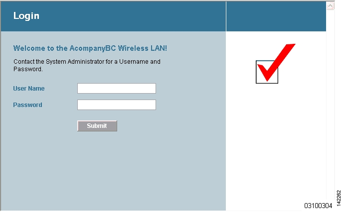
This example shows a customized Web Auth login window and the CLI commands used to create it. Figure 3-4 shows the example Web Auth login window.
Figure 3-4 Example of a Customized Web Auth Login Window
These are the CLI commands used to create the window in Figure 3-4:
>config custom-web weblogo disable>config custom-web webtitle Welcome to the AcompanyBC Wireless LAN!>config custom-web webmessage Contact the System Administrator for a Username and Password.>transfer download startMode........................................... TFTP Data Type...................................... Login Image TFTP Server IP................................. xxx.xxx.xxx.xxx TFTP Path...................................... / TFTP Filename.................................. Logo.gifThis may take some time. Are you sure you want to start? (y/n) yTFTP Image transfer starting.Image installed.>config custom-web redirecturl http://www.AcompanyBC.com>show custom-webCisco Logo................................. Disabled CustomLogo..................................... 00_logo.gif Custom Title................................... Welcome to the AcompanyBC Wireless LAN! Custom Message................................. Contact the System Administrator for a Username and Password. Custom Redirect URL............................ http://www.AcompanyBC.com External Web Authentication Mode............... Disabled External Web Authentication URL................ DisabledConfiguring Identity Networking
These sections explain the Identity Networking feature, how it is configured, and the expected behavior for various security policies:
•
•
Identity Networking Overview
In most wireless LAN systems, each WLAN has a static policy that applies to all clients associated with an SSID. Although powerful, this method has limitations since it requires clients to associate with different SSIDs to inherit different QoS and security policies.
However, the Cisco Wireless LAN Solution supports Identity Networking, which allows the network to advertise a single SSID but allows specific users to inherit different QoS or security policies based on their user profiles. The specific policies that you can control using identity networking include:
•
•
•
Note
•
Note
In order for this feature to be enabled, on a per WLAN basis, the Enable AAA Override configuration flag must be enabled.
The Operating System's local MAC Filter database has been extended to include the interface name, allowing local MAC filters to specify to which interface the client should be assigned. A separate RADIUS server can also be used, but the RADIUS server must be defined using the Security menus.
RADIUS Attributes Used in Identity Networking
This section explains the RADIUS attributes used in Identity Networking.
QoS-Level
This attribute indicates the Quality of Service level to be applied to the mobile client's traffic within the switching fabric, as well as over the air. This example shows a summary of the QoS-Level Attribute format. The fields are transmitted from left to right.
0 1 2 30 1 2 3 4 5 6 7 8 9 0 1 2 3 4 5 6 7 8 9 0 1 2 3 4 5 6 7 8 9 0 1+-+-+-+-+-+-+-+-+-+-+-+-+-+-+-+-+-+-+-+-+-+-+-+-+-+-+-+-+-+-+-+-+| Type | Length | Vendor-Id+-+-+-+-+-+-+-+-+-+-+-+-+-+-+-+-+-+-+-+-+-+-+-+-+-+-+-+-+-+-+-+-+Vendor-Id (cont.) | Vendor type | Vendor length |+-+-+-+-+-+-+-+-+-+-+-+-+-+-+-+-+-+-+-+-+-+-+-+-+-+-+-+-+-+-+-+-+| QoS Level |+-+-+-+-+-+-+-+-+-+-+-+-+-+-+-+-+-+-+-+-+-+-+-+-+-+-+-+-+-+-+-+-+•
•
•
•
•
•
–
–
–
–
ACL-Name
This attribute indicates the ACL name to be applied to the client. A summary of the ACL-Name Attribute format is shown below. The fields are transmitted from left to right.
0 1 2 30 1 2 3 4 5 6 7 8 9 0 1 2 3 4 5 6 7 8 9 0 1 2 3 4 5 6 7 8 9 0 1+-+-+-+-+-+-+-+-+-+-+-+-+-+-+-+-+-+-+-+-+-+-+-+-+-+-+-+-+-+-+-+-+| Type | Length | Vendor-Id+-+-+-+-+-+-+-+-+-+-+-+-+-+-+-+-+-+-+-+-+-+-+-+-+-+-+-+-+-+-+-+-+Vendor-Id (cont.) | Vendor type | Vendor length |+-+-+-+-+-+-+-+-+-+-+-+-+-+-+-+-+-+-+-+-+-+-+-+-+-+-+-+-+-+-+-+-+| ACL Name...+-+-+-+-+-+-+-+-+-+-+-+-+-+-+-•
•
•
•
•
•
Interface-Name
This attribute indicates the VLAN Interface a client is to be associated to. A summary of the Interface-Name Attribute format is shown below. The fields are transmitted from left to right.
0 1 2 30 1 2 3 4 5 6 7 8 9 0 1 2 3 4 5 6 7 8 9 0 1 2 3 4 5 6 7 8 9 0 1+-+-+-+-+-+-+-+-+-+-+-+-+-+-+-+-+-+-+-+-+-+-+-+-+-+-+-+-+-+-+-+-+| Type | Length | Vendor-Id+-+-+-+-+-+-+-+-+-+-+-+-+-+-+-+-+-+-+-+-+-+-+-+-+-+-+-+-+-+-+-+-+Vendor-Id (cont.) | Vendor type | Vendor length |+-+-+-+-+-+-+-+-+-+-+-+-+-+-+-+-+-+-+-+-+-+-+-+-+-+-+-+-+-+-+-+-+| Interface Name...+-+-+-+-+-+-+-+-+-+-+-+-+-+-+-•
•
•
•
•
•
Note
VLAN-Tag
This attribute indicates the group ID for a particular tunneled session, and is also known as the Tunnel-Private-Group-ID attribute.
This attribute might be included in the Access-Request packet if the tunnel initiator can predetermine the group resulting from a particular connection and should be included in the Access-Accept packet if this tunnel session is to be treated as belonging to a particular private group. Private groups may be used to associate a tunneled session with a particular group of users. For example, it may be used to facilitate routing of unregistered IP addresses through a particular interface. It should be included in Accounting-Request packets which contain Acct-Status-Type attributes with values of either Start or Stop and which pertain to a tunneled session.
A summary of the Tunnel-Private-Group-ID Attribute format is shown below. The fields are transmitted from left to right.
0 1 2 30 1 2 3 4 5 6 7 8 9 0 1 2 3 4 5 6 7 8 9 0 1 2 3 4 5 6 7 8 9 0 1+-+-+-+-+-+-+-+-+-+-+-+-+-+-+-+-+-+-+-+-+-+-+-+-+-+-+-+-+-+-+-+-+| Type | Length | Tag | String...+-+-+-+-+-+-+-+-+-+-+-+-+-+-+-+-+-+-+-+-+-+-+-+-+-+-+-+-+-+-+-+-+•
•
•
•
Tunnel Attributes
Note
Reference RFC2868 defines RADIUS tunnel attributes used for authentication and authorization, and RFC2867 defines tunnel attributes used for accounting. Where the IEEE 802.1X Authenticator supports tunneling, a compulsory tunnel may be set up for the Supplicant as a result of the authentication.
In particular, it may be desirable to allow a port to be placed into a particular Virtual LAN (VLAN), defined in IEEE8021Q, based on the result of the authentication. This can be used, for example, to allow a wireless host to remain on the same VLAN as it moves within a campus network.
The RADIUS server typically indicates the desired VLAN by including tunnel attributes within the Access-Accept. However, the IEEE 802.1X Authenticator may also provide a hint as to the VLAN to be assigned to the Supplicant by including Tunnel attributes within the Access- Request.
For use in VLAN assignment, the following tunnel attributes are used:
•
•
•
Note that the VLANID is 12-bits, taking a value between 1 and 4094, inclusive. Since the Tunnel-Private-Group-ID is of type String as defined in RFC2868, for use with IEEE 802.1X, the VLANID integer value is encoded as a string.
When Tunnel attributes are sent, it is necessary to fill in the Tag field. As noted in RFC2868, section 3.1:
•
•
•
![]()
![]()
![]()
![]()
![]()
![]()
![]()
![]()
Posted: Mon Aug 29 08:45:37 PDT 2005
All contents are Copyright © 1992--2005 Cisco Systems, Inc. All rights reserved.
Important Notices and Privacy Statement.