|
|

Table Of Contents
Antenna Patterns for 1000 Series Access Points
802.11a Internal Antenna Patterns
802.11b/g Internal Antenna Patterns
Antenna Patterns for 1000 Series Access Points
This appendix describes the antenna patterns for internal antennas on 1000 series lightweight access points. This appendix contains these sections:
•
802.11a Internal Antenna Patterns
•
802.11a Internal Antenna Patterns
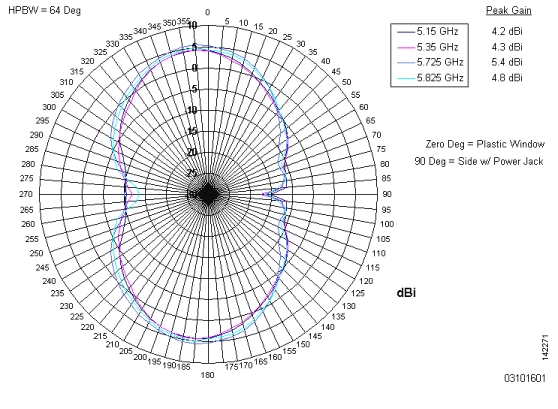
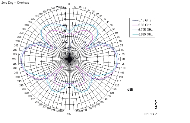
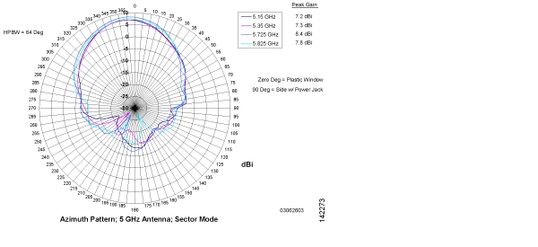
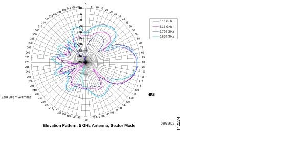
The Cisco 1000 Series lightweight access points contain one 802.11a radio, which drives two fully enclosed high-gain antennas that provide a large 360-degree coverage area. The two internal antennas are used at the same time to provide a 360-degree omnidirectional coverage area, or either antenna can be disabled to provide a 180-degree sectorized coverage area.
When equipped with an optional factory-supplied external antenna, the 802.11a Cisco Radio supports receive and transmit diversity between the internal antennas and the external antenna. The diversity function provided by Cisco Radios can result in lower multipath fading, fewer packet retransmissions, and higher client throughput.
Figure E-1, Figure E-2, Figure E-3, and Figure E-4 show radiation patterns for the lightweight access point 802.11a omnidirectional antenna.
Figure E-1 1000 Series Lightweight Access Point 802.11a OMNI (Dual Internal) Azimuth Antenna Gain Pattern
Figure E-2 802.11a OMNI (Dual Internal) Elevation Antenna Gain Pattern
Figure E-3 802.11a Sectorized (Single Internal) Azimuth Antenna Gain Pattern
Figure E-4 802.11a Sectorized (Single Internal) Elevation Antenna Gain Pattern
802.11b/g Internal Antenna Patterns
The Cisco 1000 Series lightweight access points contain one 802.11b/g radio which drives two fully enclosed high-gain antennas which can provide a large 360-degree coverage area. The two internal antennas can be used at the same time to provide a 360-degree omnidirectional coverage area, or either antenna can be disabled to provide a 180-degrees sectorized coverage area.
The 802.11b/g Cisco Radios support receive and transmit diversity between the internal antennas and/or optional factory-supplied external antennas.
Figure E-5, Figure E-6, Figure E-7, and Figure E-8 show radiation patterns for the lightweight access point 802.11b/g omnidirectional antenna.
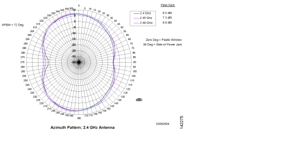
Figure E-5 802.11b/g OMNI (Dual Internal) Azimuth Antenna Gain Pattern
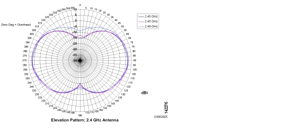
Figure E-6 802.11b/g OMNI (Dual Internal) Elevation Antenna Gain Pattern
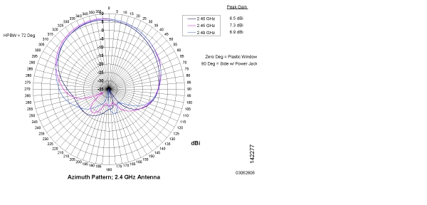
Figure E-7 802.11b/g Sectorized (Single Internal) Azimuth Antenna Gain Pattern
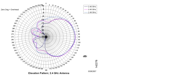
Figure E-8 802.11b/g Sectorized (Single Internal) Elevation Antenna Gain Pattern
![]()
![]()
![]()
![]()
![]()
![]()
![]()
![]()
Posted: Mon Aug 29 08:40:39 PDT 2005
All contents are Copyright © 1992--2005 Cisco Systems, Inc. All rights reserved.
Important Notices and Privacy Statement.