|
|

Table Of Contents
Connecting Temporary Terminal and Attaching Peripherals
Temporarily Connecting a Terminal or NMS to the Control Port
Powering Up the Control Terminal
Connecting a Network Printer to the BPX Switch
Auxiliary Port Parameters for Okidata 184 Local Printer
DIP Switch Settings for Okidata 184
Connecting Dial-In and Dial-Out Modems
Motorola V.34R BPX Switch Dial-In Configuration
Making External Clock Connections
Connecting Temporary Terminal and Attaching Peripherals
This chapter explains how to set up a temporary terminal or network management station for initial power-up and to attach other peripherals.
Contents of this chapter include:
•
Temporarily Connecting a Terminal or NMS to the Control Port
•
•
•
A network must have at least one connection to a control terminal or Cisco WAN Manager network management workstation. You use the Cisco WAN Manager network management workstation to configure and maintain all nodes in a network and report network statistical data.
If you wish to print, a network printer may be connected to the auxiliary port.
If you want to have Cisco Customer Service perform remote troubleshooting, you must attach a dial-in modem to the network. For more information, see the Connecting Dial-In and Dial-Out Modems section.
Before proceeding to this chapter, you should first complete the procedures in:
•
and before that, the procedures in either:
and
•
and before that, the procedures in either:
•
or
•
Before attempting to attach equipment to the BPX switch, read the manufacturer literature to ensure that you have made the equipment ready for attachment.
For the pin assignments for the BPX switch control terminal port, see "BPX Switch Cabling Summary."
For additional information, refer to the following documents:
•
•
Temporarily Connecting a Terminal or NMS to the Control Port
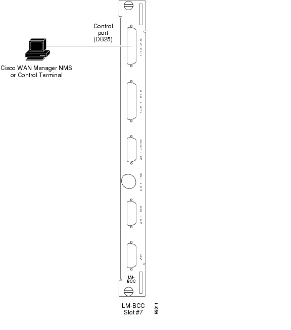
You must connect to a basic VT-100 type terminal (or PC or workstation, including a Cisco WAN Manager workstation) to the BPX control port for use in entering commands to bring up a new node. This temporary or local control is especially useful during installation, initial power-up, and configuration.
To support the Cisco WAN Manager workstation, the BPX switch LM-BCC back card offers the following ports for attaching peripherals:
•
•
•
A Cisco WAN Manager workstation is recommended for managing a network containing the IGX and BPX switches. For setup instructions and specifications for network alarm, control, and statistics monitoring for the Cisco WAN Manager network management system, refer to the Cisco WAN Manager User's Guide.
Note
The data configuration for the BPX control port is described in Table 15-1.
The BPX control and auxiliary ports are pinned as RS-232/V.24 DCE ports. When connecting a terminal, PC, or other device pinned as RS-232/V.24 DTE to the control or auxiliary port, you may use a straight-through cable. However, to connect a modem to the control or auxiliary ports, you must use a null-modem cable.
The following cards are related to the procedures:
•
•
•
To attach a terminal to the BPX switch, use the following procedure:
Step 1
Step 2
Attach the RS-232/V.24 cable as shown in Figure 15-1. Go to Step 5.Step 3
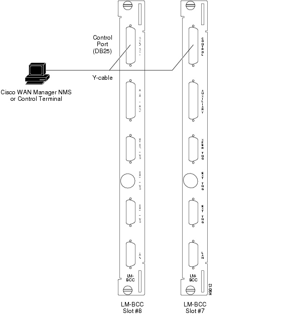
Connect one leg of the Y-cable to the CONTROL port connector on the back card in slot 7 and the other leg to the slot 8 CONTROL port connector.Step 4
Step 5
Step 6
Step 7
Next Command: cnftermfunc {a|c}[index]
Note
For parameter definitions that are used for the cnftermfunc command, refer to the Cisco WAN Switching Command Reference, Release 9.3.30.
Step 8
Control port.Step 9
Step 10
Next Command: cnfterm {a|c}[baud rate][data bits][stop bits][output flow
control{x|n}][input flow control{x|n}][CTS flow{x|n}][DTR{y|n}]
For parameter definitions that are used for the cnfterm command, refer to the Cisco WAN Switching Command Reference, Release 9.3.30.
Step 11
Step 12
Note
Powering Up the Control Terminal
After the node receives power and correctly starts up, the following terminal screen appears:
gamma TRM YourID:1 IGX 8420 9.2 Aug. 15 1998 13:47 CSTEnter User ID:If the screen is blank or does not display the initial screen, check all connections to the node, and ensure that the terminal and node are receiving power. If the connections are correct, press Delete a few times or cycle the terminal power.
Figure 15-1 Temporary Connections to Bring up a New Node, LM-BCC Back Card
Figure 15-2 Temporary Connections to Bring up a New Node, LM-BCCs
Connecting a Network Printer to the BPX Switch
In most systems, the network printer is connected to a serial port on the Cisco WAN Manager NMS terminal server. The maintenance log and all statistics data reside on the Cisco WAN Manager. For more information about specifications, refer to the Cisco WAN Manager User's Guide.
However, it is possible to connect a printer to a node and use various BPX switch software print commands to print locally. This is helpful during the initial network installation phase.
Auxiliary Port Parameters for Okidata 184 Local Printer
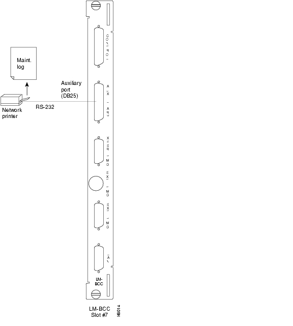
The optional local maintenance printer for the BPX switch is the Okidata Model 184 dot matrix printer. You may connect the printer to any node.
The printer configuration requirements are described in Table 15-2 and Table 15-3.
DIP Switch Settings for Okidata 184
The Dual Inline Package (DIP) switch A is an 8-section DIP switch located on the printer main circuit board.
To access the configuration switches, slide back the switch cover at the top, rear of the printer case. The settings for Switch A are listed in Table 15-3.
The High Speed Serial Interface DIP switch consists of two DIP switches, SW1 and SW2, which is located on a serial-board attached to the printer main board.
The settings for Switch 1 and Switch 2 are described in Table 15-4 and Table 15-5.
For the pin assignments for the auxiliary port on the BPX switch and the recommended RS-232/V.24 cable pinout and printer DIP switch settings, see "BPX Switch Cabling Summary."
Attaching a Local Printer
To attach the printer to the BPX switch, use the following procedure:
Step 1
Step 2
Step 3
Connect one leg of the Y-cable to the AUXILIARY port connector on the LM-BCC in slot 7.
Connect the other leg to the AUXILIARY port connector on the LM-BCC in slot 8.Step 4
Step 5
Next Command: cnftermfunc {a|c}[index]For parameter definitions that are used for the cnftermfunc command, refer to the Cisco WAN Switching Command Reference, Release 9.3.30.
Step 6
Auxiliary port.Step 7
Auxiliary port.Step 8
Next Command: cnfterm {a|c}[baud rate][data bits][stop bits][output flow
control{x|n}][input flow control{x|n}][CTS flow{x|n}][DTR{y|n}]
For parameter definitions that are used for the cnfterm command, refer to the Cisco WAN Switching Command Reference, Release 9.3.30.
Step 9
Figure 15-3 Connections to a Network Printer, LM-BCC
Connecting Dial-In and Dial-Out Modems
Cisco Customer Service uses modems to remotely diagnose and correct customer problems with installed BPX switches. You can connect to a modem to each BPX switch to provide remote access.
The modem currently recommended for use with the BPX switch is the Codex Model V.34R. You must use an auto-answer modem.
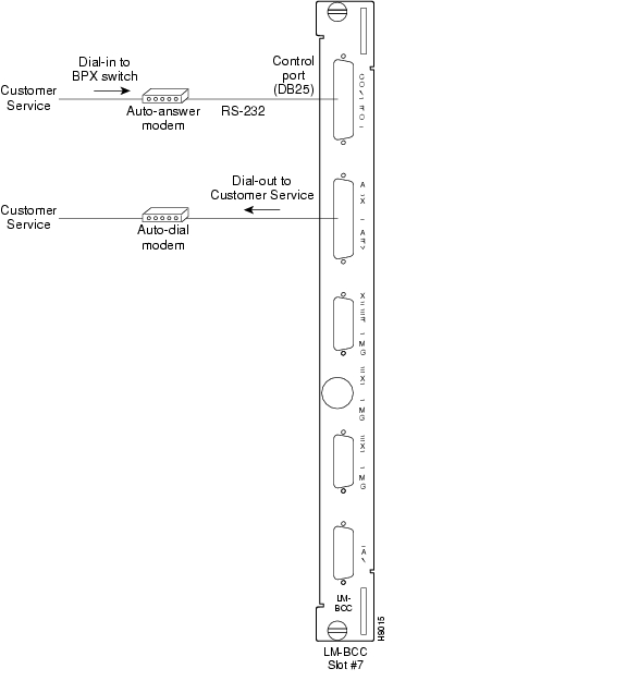
A dial-in connection to a BPX switch RS-232 from Cisco Customer Service through a modem uses the control port of the BPX switch. This port is bidirectional transmit and receive.
A dial-out connection from a BPX switch through a modem to Cisco Customer Service uses the auxiliary port of the BPX switch.
The modems connect to a standard telephone line wall jack. The modem connections require special cables and setup procedures.
If the BPX switch is equipped with redundant BCCs, you must use a RS-232 Y-cable for the connections.
The modem interface requirements are described in Table 15-6.
Figure 15-4 Connecting Modems to the BPX Switch, LM-BCC
Motorola V.34R BPX Switch Dial-In Configuration
This section describes how to configure auto-answer mode for both the V.34R modem and the BPX switch.
Enabling BPX Switch Auto-Answer (Dial-In to BPX switch)
To allow Cisco Customer Service to dial into your BPX switch to provide support and troubleshooting, use the following procedure:
Step 1
Next Command: cnfterm {a|c}[baud rate][data bits][stop bits][output flow
control{x|n}][input flow control{x|n}][CTS flow{x|n}][DTR{y|n}]
For parameter definitions that are used for the cnfterm command, refer to the Cisco WAN Switching Command Reference, Release 9.3.30.
Step 2
Step 3
Next Command: cnftermfunc {a|c}[index]For parameter definitions that are used for the cnftermfunc command, refer to the Cisco WAN Switching Command Reference, Release 9.3.30.
Step 4
Step 5
VT100/Cisco StrataView.Step 6
Step 7
Note
Step 8
Step 9
Step 10
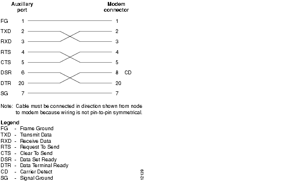
Figure 15-5 Dial-Modem Cabling for Auto Answer (Dial-In to BPX)
Enabling Auto-Dial to Cisco Customer Service
To enable your BPX to dial up Cisco Customer Service, use the following procedure:
Step 1
Next Command: cnfterm {a|c}[baud rate][data bits][stop bits][output flow
control{x|n}][input flow control{x|n}][CTS flow{x|n}][DTR{y|n}]
For parameter definitions that are used for the cnfterm command, refer to the Cisco WAN Switching Command Reference, Release 9.3.30.
Step 2
Auxiliary port.Step 3
Step 4
Step 5
Next Command: cnftermfunc {a|c}[index]{escape_string|Network ID}[Dial ID]For parameter definitions that are used for the cnftermfunc command, refer to the Cisco WAN Switching Command Reference, Release 9.3.30.
Step 6
Auxiliary port.Step 7
Autodial Modem.Step 8
Step 9
Step 10
The following are the commands used for the V.34R without a talk/data push button for the Auto-Dial Configuration (dial-out to customer service):
The following are the commands used for the V.34R with a talk/data push button for the Auto-Dial Configuration (dial-out to customer service):
Note
Step 11
Step 12
Step 13
Figure 15-6 Dial Modem Cabling for Auto Dial (dial-out to customer service)
Making External Clock Connections
If you want to synchronize the BPX switch to some other external equipment or a local digital central office, you can use one of two connectors on an BCC15-BC or BPX-BCC-3-BC back card shown in Figure 15-7 to accept a clock input.
You can use a DB15 connector labeled EXT TMG to connect a balanced T1 or E1 signal, which is synchronized from some higher-level source to the BPX switch. If an unbalanced 75-ohm E1 signal is available as the timing source, a BNC EXT TMG connector is also provided.
For a BCC-3-BC back card (back card for BCC-3-32M, BCC-3-64M, or BCC-4V), you can use a DB15 connector labeled EXT 1 TMG to connect a balanced T1 or E1 signal, which is synchronized from some higher-level source to the BPX switch.
The EXT 2 TMG connector provides a redundant connector to EXT 1 TMG. A T1 source with 100 ohm impedance or an E1 source with 100/120 ohm impedance typically uses this connector. If an unbalanced 75-ohm E1 signal is available as the timing source, a BNC EXT TMG connector is also provided.
The BPX switch can use these inputs rather than its internal Stratum 3 clock source.
Note
Figure 15-7 External Clock Source Connections to Back Cards for BCCs
![]()
![]()
![]()
![]()
![]()
![]()
![]()
![]()
Posted: Tue May 10 21:14:46 PDT 2005
All contents are Copyright © 1992--2005 Cisco Systems, Inc. All rights reserved.
Important Notices and Privacy Statement.