|
|

Table Of Contents
Installing the BPX Switch Cards
Verifying 9.6 or 19.2 Gbps Backplane
Installation of APS Redundant Frame Assembly and Back Cards
APS 1:1 Redundancy Installation
APS 1+1 Redundancy Installation
Installing the BPX Switch Cards
This chapter explains how to install the BPX switch cards, check for a 9.6 or 19.2 Gbps backplane, connect line and trunk cables, connect peripherals, connect to a network management station, initial power up, and initial configuration.
Contents of this chapter include:
•
Verifying 9.6 or 19.2 Gbps Backplane
•
Before proceeding to this chapter, you should first complete the procedures in either:
•
and
•
and before that, the procedures in either:
•
or
•
Installing the Cards
Caution
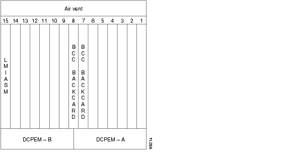
The card shelf in the BPX switch has card slots numbered from 1 to 15, as viewed from left to right from the front of the cabinet. Front and rear views of the BPX switch card shelf are shown in Figure 13-1 and Figure 13-2, respectively.
The following is a summary of the card installation rules for the BPX switch:
Nonredundant Nodes
•
BCC-4V
BCC-3-32M
BCC-3-64M, or
BCC-32
in front slot number 7.•
BCC-4V
BCC-3-32M, or
BCC-3-64M front card,
use a BCC-3-BC back card in back slot number 7,or
•
Redundant Nodes
•
BCC-4Vs,
BCC-3-32Ms,
BCC-3-64Ms, or
BCC-32s
in front slot numbers 7 and 8.•
BCC-4V,
BCC-3-32M, or
BCC-3-64M front cards
use BCC-3-BC back cards in back slot numbers 7 and 8,or
•
Note
•
•
•
•
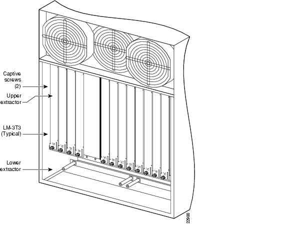
Figure 13-1 BPX Shelf (front view)
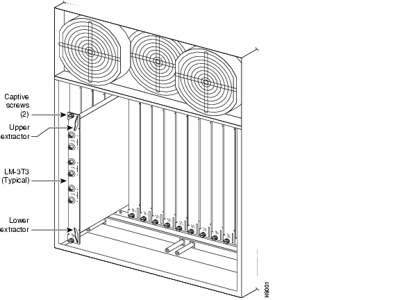
Figure 13-2 BPX Shelf (rear view, DC shelf shown)
Installing Front Cards
Before following the front card installation procedure, carefully note and perform each of the following cautionary steps:
Caution
Caution
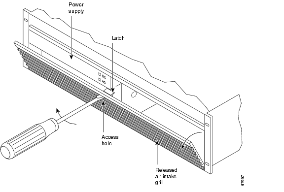
Systems may be shipped with empty shelves, with filler cards or with plug-in cards installed. If filler cards are installed in each slot, you must replace some of them may with functional cards. The front cards are held captive mechanically by the Air Intake Grille and can not be removed until the lower Air Intake Grille is released.
Caution
Caution
To remove or to install a front card, use the following procedure:
Step 1
Note
Step 2
Figure 13-3 Removing an Air Intake Grille
Step 3
Step 4
Step 5
Step 6
Step 7
Step 8
Note
Installing Back Cards
Caution
The optical ports contain an information label as shown in Figure 13-4.
Figure 13-4 Laser Information Label
Warning
Warning
Warning
To install back cards, use the following procedure:
Step 1
Step 2
Step 3
Step 4
Step 5
Note
Step 6
Step 7
Figure 13-5 Installing a Back Card
Verifying 9.6 or 19.2 Gbps Backplane
To operate the BPX switch at up to a 19.2 Gbps peak throughput, the following components are required:
•
•
•
•
•
Switch software will not allow node operation at 19.2 Gpbs unless it can read the backplane NOVRAM to verify that the backplane is a 19.2 Gbps backplane.
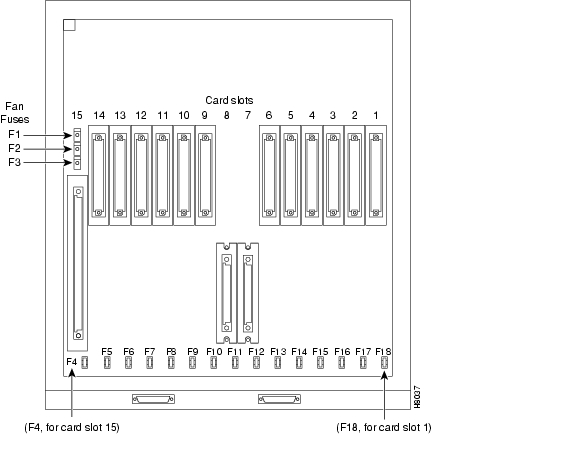
You can visually identify the 19.2 backplane by the small white card slot fan fuses at the bottom rear of the backplane shown in Figure 13-6. These fan fuses are approximately 1/4 inch high and 1/8 inch wide. The 9.6 Gbps backplane does not have these fuses.
Figure 13-6 Card slot and fan fuses, identifying the 19.2 Gpbs backplane
If the BPX Switch is a late model, then a 19.2 Gbps backplane is installed. You can verify this by running the dspbpnv command, which will display "Word #2 =0001" if the backplane NOVRAM has been programmed. If anything else is displayed, you'll have to visually check the backplane for the fuses. For information about the bit fields used for the BCC backplane NOVRAM format, see the Cisco WAN Switching Command Reference, Release 9.3.30.
If the backplane is a 19.2 Gbps backplane, but the backplane NOVRAM has not been set to display Word #2 =0001, you can use the cnfbpnv command to program the NOVRAM.
To program the NOVRAM with the cnfbpnv command, use the following procedure:
Step 1
Are you sure this is a new backplane (y/n).Step 2
Step 3
Word #2 =0001
Note
Step 4
If the backplane is not a 19.2 Gbps backplane, it is necessary to install a 19.2 Gbps backplane to obtain 19.2 Gbps operation. Contact Cisco Customer Service.
Upgrading to BCC-4 Cards
BCC-4 cards support 19.2 Gbps performance of the BXM cards.
Note
To upgrade to BCC-4 cards, use the following procedure:
Step 1
Note
Step 2
Step 3
Step 4
Step 5
Step 6
Step 7
Step 8
Step 9
After step 2, the node will contain a mix of an old type BCC and the new type BCC-4. This condition is permitted only while the standby updates to the new BCC are in progress, which takes less than one hour.
You should keep the time during which this mixture of BCC types exists to a minimum by immediately replacing the second old type BCC with the matching BCC of the new type.
Specifying Card Redundancy
You can set up port redundancy by installing two identical front and back card sets, connecting them with a Y-cable on each paired port, then specifying redundancy with the addyred command. Redundancy applies to the entire card and is not port or line-specific.
The following commands apply to Y-cable redundancy:
•
•
•
•
•
During normal operation, the primary set is "active" and carrying traffic, while the secondary set is in "standby." The primary set configuration is the configuration for both the primary and redundant set. If you reset the primary cards or the primary card set becomes inactive for another reason, the secondary card set becomes active.
BPX card sets may consist of the following:
•
•
•
•
The following requirements apply to redundant card sets:
•
•
•
•
•
•
Figure 13-7 illustrates the typical Y-cable connection of primary and secondary card sets. The single end of a Y-cable (or base of the "Y") goes to the user equipment. One of the two connectors at the split end goes to the primary back card, and the other connector goes to the secondary back card.
Switching to the standby card occurs only if the secondary card set is in a "Standby" or a "Standby-T" state (but not "Failed"). For information on the states, refer to the definition for the dspcds command of the Cisco WAN Switching Command Reference, Release 9.3.30.
Figure 13-7 Y-Cable Connection
Terminating connections is possible at only a primary slot and not at a secondary slot. For a description, refer to the addcon command of the Cisco WAN Switching Command Reference, Release 9.3.30.
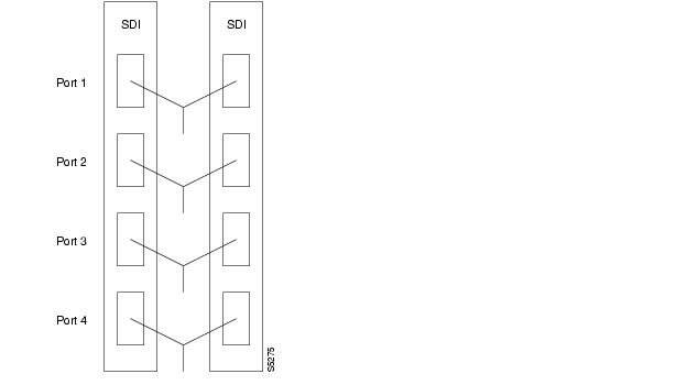
On multiport card sets, each primary port is connected by a Y-cable to a secondary (redundant) port.
Port 1 of the primary card set must be paired to port 1 of the secondary card set, and so forth. Figure 13-8 illustrates the cabling for a multiport card set.Figure 13-8 Y-Cables on Multiple Ports
If the secondary card set becomes active, the primary card set goes into the standby state. For the primary card set to serve as a backup, it must be a complete set and not have failed status.
You can execute the addyred command even if the primary and secondary slots are empty. If cards reside in the primary and secondary slots, the system checks for card compatibility. Two types of incompatibility can occur: back card and jumper or cable.
The following are the BPX mismatch types:
•
•
•
If incompatibilities exist, the message "Y-Cable Conflict" appears on screen. Specific conflicts are listed in reverse video in the Y-Cable Redundancy screen. For information about the dspyred command, refer to the Cisco WAN Switching Command Reference, Release 9.3.30.
Y-Cable redundancy is supported for both the UXM and BXM trunk cards at the edge of the ATM cloud.
Installation of APS Redundant Frame Assembly and Back Cards
The procedures in this section provide installation instructions for the SONET Automatic Protection System (APS) Redundant Frame Assemblies and back cards. These may be used to provide line and card redundancy for BXM OC-3 and OC-12 cards.
The APS protocols supported by the BXM are listed in Table 13-1.
APS 1:1 Redundancy Installation
APS 1:1 redundancy provides line redundancy only and is supported with the standard BXM OC-3 and OC-12 front and back cards. Figure 13-9 and Figure 13-10 illustrate the APS protocols for BXM.
Figure 13-9 APS 1:1 Redundancy
APS 1+1 Redundancy Installation
APS 1+1 redundancy provides both card and line redundancy. It uses the standard BXM OC-3 and OC-12 front cards but requires a special APS Redundant Backplane and APS Redundant back cards.
With previous card cages, because of the positioning of mechanical dividers, the APS card pairs could be inserted only in slots 2 through 5 and 10 through 13. The mechanical dividers are located at slots 1 and 2, 5 and 6, 9 and 10, and 13 and 14.
With current card cages, this limitation is removed so that the APS card pairs can be located anywhere except BCC cards slots 7 and 8, and ASM card slot 15. An APS 1+1 redundant card pair must be in adjacent slots (2,3 or 4,5 and so on).
Figure 13-10 APS 1+1 Redundancy
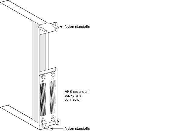
To install APS Redundant Frame Assembly and back cards, use the following procedure:
Step 1
Warning
Step 2
(see Figure 13-11).Step 3
Step 4
Figure 13-11 APS Redundant Frame Assembly
Figure 13-12 BPX Shelf, Rear View
Figure 13-13 Installing APS Redundant Frame Assembly and Back Cards into Place
![]()
![]()
![]()
![]()
![]()
![]()
![]()
![]()
Posted: Tue May 10 21:10:51 PDT 2005
All contents are Copyright © 1992--2005 Cisco Systems, Inc. All rights reserved.
Important Notices and Privacy Statement.