|
|

Table Of Contents
Installation with Cisco Cabinets including 7000 Series Routers
Installing a BPX Switch in a Cisco Cabinet
Installing a 7200 or 7500 Router in a BPX 8650 Cabinet or Rack
Installing Router Assembly in a Cisco Cabinet
Installing Router Assembly in a 19-Inch Open Rack
Installing Router Assembly in a 23-Inch Open Rack
Installation with Cisco Cabinets including 7000 Series Routers
This chapter provides the installation procedures for the Cisco cabinets along with the 7000 series routers.
Contents of this chapter include:
•
Installing a BPX Switch in a Cisco Cabinet
•
Before proceeding with this chapter, complete the procedures and safety checks in:
•
Installing a BPX Switch in a Cisco Cabinet
To install a BPX switch shelf in a Cisco cabinet while using the factory-installed rear rails located at a 19.86 inch (50.5 cm) setback from the front mounting flanges, use the following procedure:
Step 1
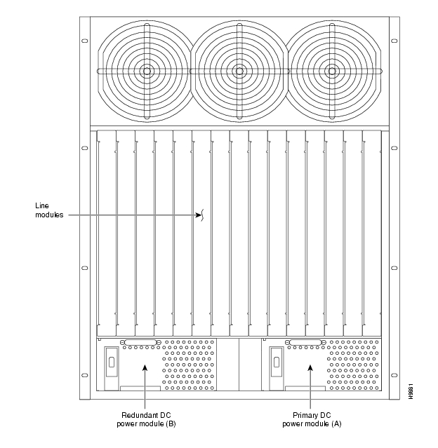
Figure 8-1 Location of DC Power Entry Module(s), Cabinet Rear View
Step 2
Step 3
Preliminary Procedure
To install either an AC- or DC-powered BPX switch shelf, use the following procedure:
Note
Step 1
Step 2
Step 3
Step 4
Note
Warning
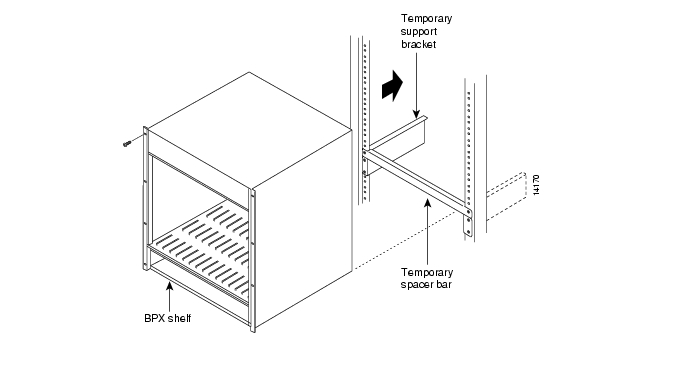
Figure 8-2 BPX Shelf Aligned with Temporary Support Brackets and Bar
Step 5
Step 6
Note
Step 7
Step 8
Step 9
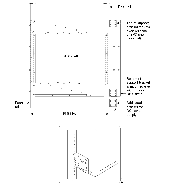
Figure 8-3 BPX Shelf with Rear Rail Mounting at Setback of 19.86 inches
Figure 8-4 Rear Mounting Brackets, with 19.86 Inch Rear Rail Setback (DC Systems)
Figure 8-5 Rear Mounting Brackets, 19.86 Inch Rear Rail Setback (AC-Systems)
Installing a 7200 or 7500 Router in a BPX 8650 Cabinet or Rack
To install the 7200 or 7500 Router Label Switch Controller assembly in a Cisco cabinet as part of a BPX 8650 installation, use the following procedure:
Note
Step 1
a.
b.
c.
Note
d.
e.
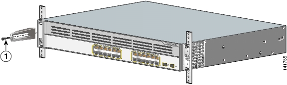
Figure 8-6 Assembly of Router in Router Enclosure
Step 2
•
•
•
Installing Router Assembly in a Cisco Cabinet
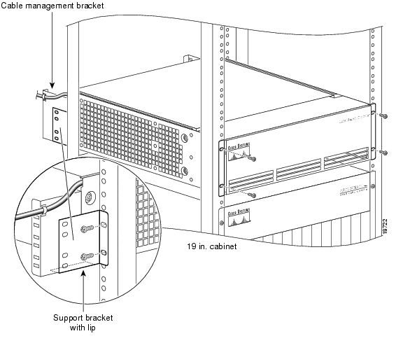
To install the router enclosure assembly in BPX 8650 cabinet (see Figure 8-7), use the following procedure:
Step 1
Step 2
Step 3
Step 4
Step 5
Step 6
Step 7
Step 8
Figure 8-7 Installing the Router Enclosure Assembly in the Cisco BPX 7650 Cabinet
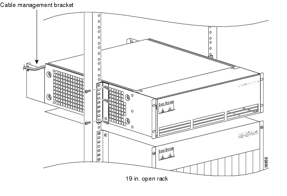
Installing Router Assembly in a 19-Inch Open Rack
To install the router enclosure assembly in BPX 8650 cabinet (see Figure 8-8), use the following procedure:
Step 1
Step 2
Step 3
Step 4
Step 5
Step 6
Step 7
Figure 8-8 Installing the Router Enclosure Assembly in a 19-inch Open Rack
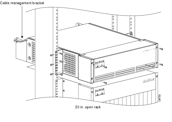
Installing Router Assembly in a 23-Inch Open Rack
To install the router enclosure assembly in BPX 8650 cabinet (see Figure 8-9), use the following procedure:
Step 1
Step 2
Step 3
Step 4
Step 5
Step 6
Step 7
Step 8
Figure 8-9 Installing the Router Enclosure Assembly in a 23-inch Open Rack
![]()
![]()
![]()
![]()
![]()
![]()
![]()
![]()
Posted: Tue May 10 21:09:24 PDT 2005
All contents are Copyright © 1992--2005 Cisco Systems, Inc. All rights reserved.
Important Notices and Privacy Statement.