|
|

Table Of Contents
Installing the T3/E3 Cable Management Tray
Installation of Cable Management Tray
Raising Tray for Access to PEMs
Installing BXM T3/E3 Cable Bracket
Connecting Cables to BXM T3/E3 Cards
Routing Cables from Cards through Cable Management Tray
Tray Raised with Cables in Place
Installing the T3/E3 Cable Management Tray
This chapter provides instructions for the installation of the optional cable management tray that you can use to route cables in an open-rack, nonredundant configuration.
Contents of this chapter include:
•
Installation of Cable Management Tray
•
•
•
•
•
You must obtain the optional cable management tray kit and one each BXM T3/E3 cable bracket kit for each BXM T3/E3 card.
Installation of Cable Management Tray
This section describes the steps to install the cable management tray.
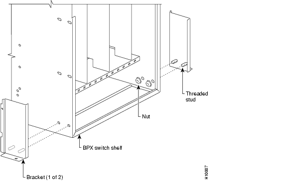
Installing Tray Brackets
To install tray brackets, use the following procedure:`
Step 1
Step 2
Figure 12-1 Installation of Cable Management Tray Brackets
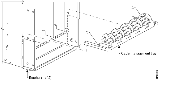
Installing Tray
To install a tray, use the following procedure:
Step 1
Step 2
Figure 12-2 Sliding Cable Management Tray over Brackets
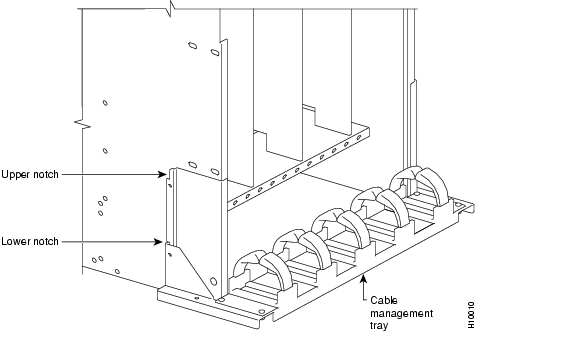
Figure 12-3 Cable Management Tray in Lowered Home Position
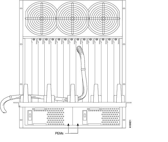
Raising Tray for Access to PEMs
You should raise the tray only when necessary to access the Power Entry Modules (PEMs), typically for replacement or to install a second PEM. Figure 12-4 shows the tray in the raised position.
To raise the tray to provide access to the PEMs, use the following procedure:
Step 1
Step 2
Step 3
Figure 12-4 Cable Management Tray in Raised Position
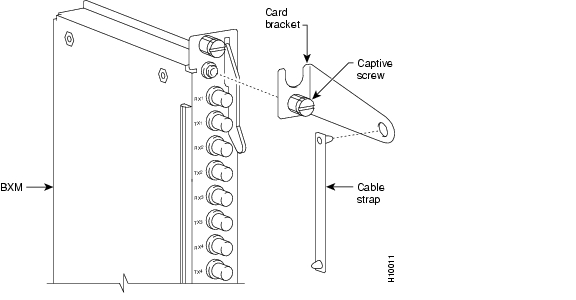
Installing BXM T3/E3 Cable Bracket
To attach the BXM T3/E3 cable bracket to each BXM T3/E3 card as shown in Figure 12-5, use the following procedure:
Step 1
Step 2
Step 3
Step 4
Figure 12-5 Installing BXM T3/E3 Cable Bracket
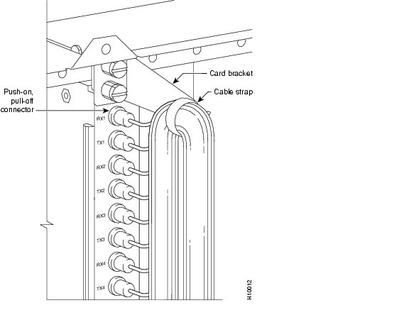
Connecting Cables to BXM T3/E3 Cards
To route the cables as shown in Figure 12-6 and Figure 12-7, use the following procedure:
Step 1
Step 2
Step 3
Step 4
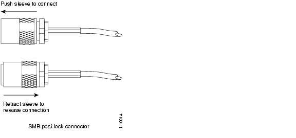
Note
Figure 12-6 Connecting Cables to T3/E3 Card
Figure 12-7 T3/E3 SMB Connector Detail
Routing Cables from Cards through Cable Management Tray
To route cables as shown in Figure 12-8, use the following procedure:
Step 1
Step 2
Step 3
Figure 12-8 Cables Routed through Cable Management Tray in Lowered Position
Tray Raised with Cables in Place
To provide access to the Power Entry Modules (PEMs), raise the cable management tray with cables in place as shown in Figure 12-9.
Figure 12-9 Tray Raised with Cables in Place
![]()
![]()
![]()
![]()
![]()
![]()
![]()
![]()
Posted: Tue May 10 21:07:25 PDT 2005
All contents are Copyright © 1992--2005 Cisco Systems, Inc. All rights reserved.
Important Notices and Privacy Statement.