cc/td/doc/product/wanbu/bpx8600/9_3_3
hometocprevnextglossaryfeedbacksearchhelp
PDF

Table Of Contents

Connecting Cables

Making T3 or E3 Connections

Making a BXM OC-3 or OC-12 Connection

Making a BXM T3/E3 Connection

Setting up the BME OC-12 Port Loop

Alarm Output Connections


Connecting Cables


This chapter explains how to connect trunk and circuit line cables.

Contents of this chapter include:

Making T3 or E3 Connections

Making a BXM OC-3 or OC-12 Connection

Making a BXM T3/E3 Connection

Setting up the BME OC-12 Port Loop

Alarm Output Connections

Before proceeding to this chapter, you should first complete the procedures in:

Chapter 13, "Installing the BPX Switch Cards"

and before that, the procedures in either:

"Installing the DC Shelf"

"Installing the AC Shelf"

and

"Installing the T3/E3 Cable Management Tray"

and before that, the procedures in either:

"Installation with Cisco Cabinets including 7000 Series Routers"

or

"Installation in Customer Cabinet"

Making T3 or E3 Connections

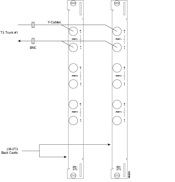
Each LM-3T3 and LM-3E3 line module (BNI back card) provides three ports with a BNC connector each for the XMT trunk output and for the RCV trunk input.

Each LM-2T3 and LM-2E3 line module provides two ports with a BNC connector each for the XMT line output and for the RCV line input.

To make the T3/E3 connections to each port, use the following procedure:


Step 1 Bring each cable through the opening at the bottom of the cabinet at the back and route them up the side.

Step 2 The BPX switch has velcro tie-downs inside the cabinet to hold cabling in place. Pull the tie-downs apart as applicable, place the routed cable in position, wrap the ties around the cable and remake the loops by pressing the two sections together.

Step 3 Connect the cables to the BNC connectors on the LM-3T3 or LM-3E3 line modules. Remember, the RCV is an input to the BPX switch and XMT is an output from the BPX switch. The ports are numbered from top to bottom as shown in Figure 14-1.

Figure 14-1 Connecting T3 Cables to BPX LM-T3 (BNI T3 back card)


Note Maximum distance from a BPX switch to a DSX3 cross connect point is approximately 450 feet (150 meters).


Step 4 Record which slot and port number you are using for each trunk or line. You will need this information later when configuring the network.

Step 5 If optional Y-cable redundancy is desired, locate a 3-way BNC Y-cable adapter for each port to be so equipped. As an alternative to the Y-cable, use a BNC "T" and two short, equal-length BNC-BNC cables.

Step 6 For card redundancy, ensure there are two appropriate line modules equipped in adjacent slots.

Step 7 Connect two legs of the Y-cable to the XMT T3 or E3 connectors on the same port on each of the two line modules as shown in Figure 14-2. Do the same with the two RCV T3 or E3 connectors.

Step 8 Connect the third leg of the XMT and RCV Y-cable adapters to the XMT and RCV trunk cable.

Figure 14-2 Connecting Y-Cable Adapters to a T3 Port


Making a BXM OC-3 or OC-12 Connection

Each OC-3 or OC-12 line module provides ports with both a transmit and receiver connector for each port. This procedure applies to OC-3 and OC-12 back cards, except that Y-Cabling redundancy is supported only for the SMF cards.

To make BXM OC-3 or OC-12 connections, use the following procedure:


Step 1 At the back of the cabinet, route each cable up the inside of the cabinet, as applicable.

Step 2 The Cisco cabinet has tie-downs inside the cabinet to hold cabling in place. If using a Cisco cabinet, pull the tie downs apart as applicable, place the routed cable in position, wrap the ties around the cable and remake the loops by pressing the two sections together.

Step 3 Connect the cables to the applicable connectors on the line modules.
Remember, the RCV is an input to the BPX switch and XMT is an output from the BPX switch. The ports are numbered from top to bottom.

Step 4 Record which slot and port number you are using for each trunk or line. You will need this information later when configuring the network.

A Y-Cable redundancy connection for the SMF-2-BC back card is shown in Figure 14-3.

Figure 14-3 Connecting Y-Cables to an OC-3-SMF Back Card

Step 5 For card redundancy, make sure there are two appropriate line modules equipped in adjacent slots.

Step 6 Connect two legs of the Y-cable to the XMT connectors on the same port on each of the two line modules (see Figure 14-3). Do the same with the two RCV connectors.

Y-redundancy is supported on the following cards:

SMF-155-8-BC

SMFLR-155-8-BC

SMF-155-4-BC

SMFLR-155-4-BC

SMF-622-2-BC

SMFLR-622-2-BC

SMF-622-BC

SMFLR-622-BC

BPX-XLR-622-BC

BPX-XLR-622-2-BC

BPX-STM1-EL-4-BC


Making a BXM T3/E3 Connection

Each T3/E3 line module provides ports with both a transmit and receiver connector for each port. The back cards can provide 4, 8, or 12 ports.

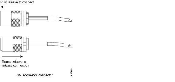
Figure 14-4 shows a typical T3/E3 cable connector that connects to the BXM T3/E3 cards.

Figure 14-4 BXM T3/E3 Cable Connector Detail

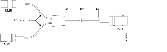
Y-Cabling redundancy is supported on the BXM T3/E3 cards. An example of a Y-cable is shown in Figure 14-5.

Figure 14-5 Y-Cable for BXM T3/E3 Cards

To make a BXM T3/E3 connection, use the following procedure:


Step 1 At the back of the cabinet, route each cable up the inside of the cabinet, as applicable. If Y-cables are used, the Y-cable connects to the corresponding connectors on adjacent cards.

Step 2 The Cisco cabinet has velcro tie-downs inside the cabinet to hold cabling in place. If using a Cisco cabinet, pull the tie downs apart as applicable, place the routed cable in position, wrap the ties around the cable and remake the loops by pressing the two sections together.

Step 3 Connect the cables to the applicable connectors on the T3/E3 line modules.

Remember, the RCV is an input to the BPX switch and XMT is an output from the BPX switch. The ports are numbered from top to bottom.

Step 4 For an open rack configuration in which Y-redundancy is not being used, an optional cable management tray is available. This is helpful for routing cables when a number of DS3/T3 cards are installed resulting a large number of cables to handle. For more information, see "Installing the T3/E3 Cable Management Tray."


Setting up the BME OC-12 Port Loop

To set up the two ports on the OC-12 back card for the BME multicast card, connect both:

the transmit of port 1 to the receive of port 2

the receive to port 1 to the transmit of port 2

Thus, you have looped the two ports together as shown in Figure 14-6.

Figure 14-6 Looping Ports 1 and 2 for BME on OC-12 Back Card

Alarm Output Connections

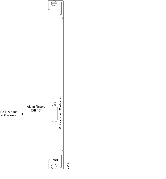
Dry contact relay closures are available for forwarding BPX switch alarms to a user office alarm system. Separate visual and audible alarm outputs are available for both major as well as minor alarm outputs.

These outputs are available from a DB15 connector on the LM-ASM faceplate as shown in Figure 14-7. For a list of the pinouts for this connector, see "BPX Switch Cabling Summary." Use switchboard cable for running these connections.

Figure 14-7 Alarm Output Connector


hometocprevnextglossaryfeedbacksearchhelp

Posted: Tue May 10 21:12:51 PDT 2005
All contents are Copyright © 1992--2005 Cisco Systems, Inc. All rights reserved.
Important Notices and Privacy Statement.