|
|

Table Of Contents
Managing the Configuration Files
Clearing a Switch Configuration
Restoring a Saved Configuration
Enabling and Disabling ILMI on a Port
Displaying the ILMI Port Configuration
Displaying and Clearing ILMI Management Statistics
Determining the Software Version Number from Filenames
Displaying Software Revisions for Cards
Displaying Software Revisions in Use
Displaying Software Revisions for a Single Card
Switching Between Redundant PXM Cards
Switching Between Redundant Service Modules
Removing Redundancy Between Two Cards
Switching Between Redundant RPM Cards
Configuring Intercard APS Lines
Displaying APS Line Information
Removing APS Redundancy Between Two Lines
Managing Network Clock Sources
Deleting an Existing SNTP Server
Displaying the Current SNTP Configuration
Configuring an NCDP Clock Source
Managing Manually Configured Clocks Sources
View the Configured Clock Sources
Reconfigure Manual Clock Sources
Restore a Manual Clock Source After Failure
Viewing an ATM Port Configuration
Displaying a PXM1E Resource Partition Configuration
Changing a PXM1E Resource Partition Configuration
Deleting a PXM1E Resource Partition
Configuring VPI and VCI Ranges for SVCs and SPVCs
Establishing Priority Routing on a Node
Configuring Priority Routing on a Connection
Modifying SPVC Priority Routing Configuration
Managing Path and Connection Traces
Displaying Path and Connection Traces
Clearing a Call at the Destination Node
Displaying Load Sharing Status
Starting and Managing Telnet Sessions to Other Switches
Returning to a Previous Session
Returning to the Original CLI Session
Displaying the Contents of the Disk Verification Utility Log File
Troubleshooting Active and Standby Card Disk Discrepancies
Configuring Loopback Line Tests on PXM1E and AXSM Cards
Configuring a Line Loopback on a CBSM
Configuring a Bit Error Rate Test
Deleting a Configured Bit Error Rate Test
Diagnostics Support on PXM1E and AXSM Cards
Configuring Offline and Online Diagnostics Tests on PXM1E and AXSM Cards
Enabling Online and Offline Diagnostics Tests on All Cards in a Switch
Displaying Online and Offline Diagnostics Test Configuration Information
Enabling and Disabling IMA Group ATM Cell Layer Parameters
2
3
Switch Operating Procedures
This chapter describes procedures you can use to manage the Cisco MGX 8850 (PXM1E/PXM45), Cisco MGX 8950, and Cisco MGX 8830 switches.
Managing the Configuration Files
The following sections describe how to save a switch configuration in a single zipped file, clear or erase a configuration, and restore a configuration from a file.
Saving a Configuration
After configuring your switch or after making configuration updates, it is wise to save the configuration. Restoring a saved configuration is much easier than re-entering all the commands used to configure the switch.
To save a configuration, enter the saveallcnf command, which saves the configuration to a file in the C:/CNF directory. The file is named using the switch name and the current date as follows:
Name_01_DateTime.zip.
The date appears in YYYYMMDD (year, month, day) format, and the time appears in HHMM (hour, minute) format. For example, if the configuration for a switch named mgx8850a were saved on February 29th, 2000 at 2:31pm, the file would be named C:/CNF/mgx8850a_01_200002291431.zip.
When you save a configuration, the switch saves all configuration data, including the software revision levels used by the cards in the switch. The saved configuration file does not include the boot and runtime software files. Should you need to restore a configuration, the restoreallcnf command restores the configuration exactly as it was when the configuration file was saved. If the boot and runtime files have been removed from the switch, they must be transferred to the switch before the restored configuration can start.
Note
If you have upgraded software on the switch since the last time the configuration was saved, a configuration restore will restore the non-upgraded software versions and configuration data. The software does not allow you to save a configuration and restore it on a different revision level of the software.
You can save a configuration if both of the following are true:
•
•
Caution
To save a switch configuration, use the following procedure.
Step 1
Step 2
mgx8830a.7.PXM.a > saveallcnf [-v]The verbose option, -v, displays messages that show what the switch is doing during the save process. You do not need to see these messages, but they do give you an indication on how the save process is proceeding. If you do not enter the -v option, the switch does not display any status messages until the save is complete.
Step 3
When the save is complete, the switch prompt reappears, and the new file is stored in the C:/CNF directory.
Note
The following example shows what appears on the switch when the saveallcnf command is used without the -v option:
mgx8830a.1.PXM.a > saveallcnfThe 'saveallcnf' command can be time-consuming. The shelfmust not provision new circuits while this command is running.Do not run this command unless the shelf configuration is stableor you risk corrupting the saved configuration file.ATTENTION PLEASE NOTE:-> If you want to abort the save, please use abortallsaves CLI.If you use cntrl-C, you will risk hanging the whole telnetsession and may lose capability of being able to performsubsequent saves-> The save command will only store the2 most recent saved files in C:/CNF directory.If you have 2 or more files already saved in C:/CNF,the older ones will be deleted by the current save,keeping the 2 most recent.Do you want to proceed (Yes/No)? ysaveallcnf: shelf configuration saved in C:/CNF/pop20one_01_200006151550.zip.
Note
Clearing a Switch Configuration
There are two commands that allow you to clear the switch configuration: clrcnf and clrallcnf.
To clear switch provisioning data such as the PNNI controller and SPVC connections, enter the clrcnf command. This command clears all configuration data except the following:
•
•
•
•
•
To clear the entire configuration, use the clrallcnf command. This command clears all the provisioning data and most of the general switch configuration parameters, such as the switch name and SNMP configuration. The clrallcnf command clears all IP addresses except the boot IP address.
Clearing a Slot Configuration
To clear the entire configuration on both the RAM and the disk for a specified service module slot, enter the clrsmcnf command. If you enter clrsmcnf <slot> without any options, only the RAM and disk will be cleared. If you enter clrsmcnf <slot> -all, card specific information will be cleared along with the RAM and disk.
The service module will go into reboot, and then it will come back up in the previous revision.
Enter the dspcd command to verify whether the clrsmcnf command was successful or not.
Note
Caution
Restoring a Saved Configuration
You can restore a configuration if all of the following statements are true:
•
•
•
Caution
To restore a saved switch configuration, use the following procedure.
Step 1
Step 2
Note
Tip
Step 3
mgx8830a.1.PXM.a > restoreallcnf -f filename
Caution
Note
Replace filename with the name of the saved configuration file.You do not have to enter the path to the file or the extension. For information on the location and name of the file, see " Saving a Configuration."
Managing ILMI
The following sections describe how to
•
•
•
•
Enabling and Disabling ILMI on a Port
The Cisco MGX switches provide several commands that you can use to enable or disable ILMI on a port. For instructions on enabling or disabling ILMI from a PXM1E card, see the " Configuring ILMI on a Port" section in Chapter 11, "Provisioning PXM1E Communication Links." For instructions on enabling or disabling ILMI from a AXSM card, see refer to the Cisco ATM Services (AXSM) Software Configuration Guide and Command Reference for MGX Switches.
To enable or disable ILMI from the PXM prompt, use the following procedure.
Step 1
Step 2
To enable or disable ILMI on a port, enter the cnfilmienable command as follows:
mgx8830a.1.PXM.a>cnfilmienable <portid> <no | yes>Replace portid using the format slot:bay.line:ifNum. Table 13-1 describes these parameters.
Enter yes to enable ILMI on the port, or enter no to disable ILMI.
Step 3
Displaying the ILMI Port Configuration
The following procedure describes some commands you can use to view the ILMI port configuration.
Step 1
Step 2
mgx8830a.1.PXM.a > dspilmisSig. rsrc Ilmi Sig Sig Ilmi S:Keepalive T:conPoll K:conPollPort Part State Vpi Vci Trap Interval Interval InactiveFactor---- ---- ---- ---- ---- --- ------------ ---------- ----------1 1 Off 0 16 On 1 5 43 1 Off 0 16 On 1 5 4The example above shows that all ports are configured for the default ILMI values and that ILMI has not been started on any port. Table 13-2 describes each of the report columns.
Step 3
mgx8830a.1.PXM.a > dspilmi <ifnum> <partitionId>Replace ifnum with the interface number of the port, and replace partitionID with the partition number assigned to the port. You can view both of these numbers in the dspilmis command report. The following is an example report for the dspilmi command. Table 13-2 describes each of the columns that appear in the command report.
mgx8830a.1.PXM.a > dspilmi 1 1Sig. rsrc Ilmi Sig Sig Ilmi S:Keepalive T:conPoll K:conPollPort Part State Vpi Vci Trap Interval Interval InactiveFactor---- ---- ---- ---- ---- --- ------------ ---------- ----------1 1 On 0 16 On 1 5 4Step 4
mgx8830a.1.PXM.a > dsppnportsSummary of total connections(p2p=point to point,p2mp=point to multipoint,SpvcD=DAX spvc,SpvcR=Routed spvc)Type #Svcc: #Svpc: #SpvcD: #SpvpD: #SpvcR: #SpvpR: #Total:p2p: 0 0 0 0 0 0 0p2mp: 0 0 0 0 0 0 0Total=0Summary of total configured SPVC endpointsType #SpvcCfg: #SpvpCfg:p2p: 0 0p2mp: 0 0Per-port status summaryPortId IF status Admin status ILMI state #Conns7.35 up up Undefined 07.36 up up Undefined 07.37 up up Undefined 07.38 up up Undefined 0Type <CR> to continue, Q<CR> to stop:10:1.1:1 up up UpAndNormal 0The ILMI operational state is displayed as one of the following: Disable, EnableNotUp, or UpAndNormal. When ILMI is disabled on the port, the operational status is Disable. When ILMI is enabled on the local port but cannot communicate with ILMI on the remote port, the status is EnableNotUp. In other words, the EnableNotUp status happens when ILMI is disabled on the remote end. When ILMI is enabled and communicating with ILMI on the remote port, the ILMI state is UpAndNormal.
Step 5
mgx8830a.1.PXM.a > dsppnilmi <portid>Replace portid using the format slot:bay.line:ifNum. Table 13-1 describes these parameters. The following example shows the format of the dsppnilmi command report.
mgx8830a.1.PXM.a > dsppnilmi 10:1.1:1Port: 10:1.1:1 Port Type: PNNI Side: networkAutoconfig: disable UCSM: disableSecure Link Protocol: enableChange of Attachment Point Procedures: enableModification of Local Attributes Standard Procedure: enableAddressreg: Permit AllVPI: 0 VCI: 16Max Prefix: 16 Total Prefix: 0Max Address: 64 Total Address: 0Resync State: 0 Node Prefix: yesPeer Port Id: 16848897 System_Id : 0.80.84.171.226.192Peer Addressreg: enablePeer Ip Address : 0.0.0.0Peer Interface Name : atmVirtual.01.1.1.01ILMI Link State : UpAndNormalILMI Version : ilmi40INFO: No Prefix registeredDisplaying and Clearing ILMI Management Statistics
The following procedure describes some commands you can use to view ILMI management statistics.
Step 1
mgx8830a.1.PXM.a > dspilmicnt <ifnum> <partitionId>Replace ifnum with the interface number of the port, and replace partitionID with the partition number assigned to the port. You can view both of these numbers in the dspilmis command report. The following is an example report for the dspilmicnt command.
mgx8830a.1.PXM.a > dspilmicnt 1 1If Number : 1Partition Id : 1SNMP Pdu Received : 36914GetRequest Received : 18467GetNext Request Received : 0SetRequest Received : 0Trap Received : 1GetResponse Received : 18446GetResponse Transmitted : 18467GetRequest Transmitted : 18446Trap Transmitted : 4Unknown Type Received : 0ASN1 Pdu Parse Error : 0No Such Name Error : 0Pdu Too Big Error : 0
Note
Step 2
mgx8830a.1.PXM.a > clrilmicnt <ifnum> <partitionId>Replace ifnum with the interface number of the port, and replace partitionID with the partition number assigned to the port. The following example shows the switch response to this command.
mgx8830a.1.PXM.a > clrilmicnt 1 1ilmi stats for ifNum 1, partId 1 clearedStep 3
Deleting ILMI Prefixes
The following procedure describes how to delete an ILMI address prefix from a port.
Note
Step 1
Step 2
mgx8830a.1.PXM.a > dspprfx <portid>Replace <portid> with the port address using the format slot:bay.line:ifnum. These parameters are described in Table 13-1. For example:
mgx8830a.1.PXM.a > dspprfx 10:2.2:4INFO: No Prefix registeredIn the example above, no ILMI prefixes have been assigned to the port, so the port will use the prefix configured for the SPVC prefix.
Step 3
mgx8830a.1.PXM.a > dnpnport 10:2.2:4Step 4
mgx8830a.1.PXM.a > delprfx <portid> <atm-prefix>Replace portid using the format slot:bay.line:ifNum. Table 13-1 describes these parameters.
Replace atm-prefix with the 13-byte ATM address prefix in use.
Step 5
mgx8830a.1.PXM.a > uppnport 10:2.2:4Step 6
Determining the Software Version Number from Filenames
The following version management commands require a version number to be entered in a specific format:
•
•
•
•
•
•
In most cases, you will find the correct firmware version numbers in the Release Notes for Cisco MGX 8850 (PXM1E/PXM45), Cisco MGX 8950, and Cisco MGX 8830, Software Version 4.0.00. If the release notes are not available, you can use the firmware filename to determine the version number as described below.
Step 1
Step 2
mgx8830a.1.PXM.a > cd C:/FW
Note
Step 3
mgx8830a.1.PXM.a > llThe following example shows the ll command display:
mgx8830a.1.PXM.a > ll-rwxrwxrwx 1 0 0 1367596 Mar 12 18:27 ausm_8t1e1_020.000.000.106-D.fw-rwxrwxrwx 1 0 0 967736 Apr 11 18:43 pxm1e_002.001.050.000-D_diag.fw-rwxrwxrwx 1 0 0 6476612 Mar 29 23:51 pxm1e_003.000.000.000-D_mgx.fw-rwxrwxrwx 1 0 0 1123104 Mar 6 18:26 pxm1e_003.000.000.000-D_diag.fw-rwxrwxrwx 1 0 0 6412036 Feb 27 19:39 pxm1e_003.000.000.206-P1_m30.fw-rwxrwxrwx 1 0 0 3810744 Feb 26 23:54 vism_8t1e1_003.000.000.051-I.fw-rwxrwxrwx 1 0 0 3811160 Feb 26 19:21 vism_8t1e1_003.000.000.050-I.fw-rwxrwxrwx 1 0 0 1085856 Jan 5 2000 pxm1e_001.001.050.005-A_diag.fw-rwxrwxrwx 1 0 0 6327220 Feb 1 00:02 pxm1e_003.000.000.185-P2_m30.fw-rwxrwxrwx 1 0 0 1015768 Feb 1 00:02 pxm1e_003.000.000.185-P2_bt.fw-rwxrwxrwx 1 0 0 6331172 Jan 29 00:24 pxm1e_003.000.000.185-A_mgx.fw-rwxrwxrwx 1 0 0 878976 Jan 1 2098 pxm1e_002.001.050.007-A_bt.fw-rwxrwxrwx 1 0 0 725744 Mar 12 18:27 cesm_8t1e1_020.000.000.106-D.fw-rwxrwxrwx 1 0 0 867564 Mar 12 18:27 frsm_8t1e1_020.000.000.106-D.fw-rwxrwxrwx 1 0 0 1004548 Mar 12 18:28 frsm_vhs_020.000.000.106-D.fw-rwxrwxrwx 1 0 0 6524548 May 3 00:38 pxm1e_003.000.000.000-D_m30.fw-rwxrwxrwx 1 0 0 6505668 Apr 29 23:24 pxm1e_003.000.000.026-P4_m30.fwIn the file system :total space : 819200 K bytesfree space : 786279 K bytes
Note
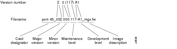
Figure 13-1 shows the information contained in filenames for released software.
Figure 13-1 Filename Format for Released Software
Filenames that include "_mgx" are for runtime PXM firmware, and filenames that include "_bt" are for boot firmware. Service module runtime firmware images do not have an image description after the version number. When you first receive the switch from Cisco, there will be single versions of each file. If you download updates to any files, there will be multiple versions of those files.
Figure 13-2 shows the information contained in filenames for prereleased firmware. If you are evaluating nonreleased firmware, the filename format shows that the firmware is prereleased and indicates the development level of the prerelease firmware.
Figure 13-2 Filename Format for Prereleased Firmware
Step 4
Write the version number in the format required by the revision management commands. The following example shows the required format. If you are logged in as a user with SERVICE_GP access privileges, you can display this example by entering any of the revision management commands without parameters.
mgx8830a.1.PXM.a > runrevERR: Syntax: runrev <slot> <revision>slot -- optional; value: 15,16,31,32revision - revision number. E.g.,2.0(1)2.0(1.255)2.0(0)I or 2.0(0)A2.0(0)P1 or 2.0(0)P22.0(0)P3 or 2.0(0)P42.0(0)D2.0(1.166)I or 2.0(1.166)A2.0(1.166)P1 or 2.0(1.166)P22.0(1.166)P3 or 2.0(1.166)P4The first example above, 2.0(1), is for released firmware version 2.0, maintenance release 1. The second example, 2.0(1.255), is for patch 255 to version 2.0, maintenance release 1. The other examples are for prerelease firmware. Prerelease firmware does not include patches; the maintenance release number is increased for each software change.
Table 13-3 shows some example filenames and the correct version numbers to use with the revision management commands.
Displaying Software Revisions for Cards
This section describes how to display software revision information for the cards in your switch.
Displaying Software Revisions in Use
To display the boot and runtime software version in use on every card in the switch, enter the dsprevs command as shown in the following example:
mgx8830a.1.PXM.a > dsprevsUnknown System Rev: 03.00 May. 04, 2002 20:24:57 GMTMGX8830 Node Alarm: MINORPhy. Log. Inserted Cur Sw Boot FWSlot Slot Card Revision Revision---- ---- -------- -------- --------01 01 PXM1E-4-155 3.0(0.26)P4 3.0(0.26)A02 01 PXM1E-4-155 3.0(0.26)P4 3.0(0.26)A03 03 --- --- ---04 04 FRSM_2CT3 --- ---05 05 FRSM_2CT3 --- ---06 06 CESM_8T1 --- ---07 07 SRM_3T3 --- ---08 08 --- --- ---09 09 --- --- ---10 10 --- --- ---11 11 FRSM_8T1 --- ---12 12 --- --- ---13 13 FRSM_8T1 --- ---14 07 SRM_3T3 --- ---To display the upgrades status of the runtime software on all switch cards, enter the dsprevs -status command as shown in the following example:
mgx8830a.1.PXM.a > dsprevs -statusCorvette System Rev: 03.00 Jun. 07, 2002 19:12:23 GMTMGX8830 Node Alarm: MINORPhy. Log. Cur Sw Prim Sw Sec Sw Rev ChgSlot Slot Revision Revision Revision Status---- ---- -------- -------- -------- -------01 01 3.0(0.83)D 3.0(0.83)D 3.0(0.83)D ---02 01 3.0(0.83)D 3.0(0.83)D 3.0(0.83)D ---03 03 --- --- --- ---04 04 20.0(1.44)A 20.0(1.44)A 20.0(1.44)A ---05 04 20.0(1.44)A 20.0(1.44)A 20.0(1.44)A ---06 06 20.0(1.44)A 20.0(1.44)A 20.0(1.44)A ---07 07 --- --- --- ---08 08 --- --- --- ---09 09 --- --- --- ---10 10 --- --- --- ---11 11 20.0(1.44)A 20.0(1.44)A 20.0(1.44)A ---12 12 --- --- --- ---13 13 --- --- --- ---14 07 --- --- --- ---Displaying Software Revisions for a Single Card
To display the boot and runtime software revisions in use on a single card, enter the dspcd <slot> command as shown in the following example:
mgx8830a.1.PXM.a > dspcd 2Unknown System Rev: 03.00 May. 04, 2002 20:29:14 GMTMGX8830 Node Alarm: MINORSlot Number 2 Redundant Slot: 1Front Card Upper Card Lower Card---------- ---------- ----------Inserted Card: PXM1E-4-155 UI Stratum3 SMFIR_4_OC3Reserved Card: PXM1E-4-155 UI Stratum3 UnReservedState: Active Active ActiveSerial Number: S1234567890 SAK0325008J SAG05415SW9Prim SW Rev: 3.0(0.26)P4 --- ---Sec SW Rev: 3.0(0.26)P4 --- ---Cur SW Rev: 3.0(0.26)P4 --- ---Boot FW Rev: 3.0(0.26)A --- ---800-level Rev: E2 03 4P800-level Part#: 800-12345-01 800-05787-01 800-18663-01CLEI Code: ύ0 0Reset Reason: On Power upCard Alarm: NONEFailed Reason: NoneMiscellaneous Information:Type <CR> to continue, Q<CR> to stop:Managing Redundant Cards
The MGX switches support redundancy between two cards of the same type. For PXM1E, PXM45, and SRM cards, this redundancy is preconfigured on the switch. To establish redundancy between two CBSMs (for example, CESM, AUSM, FRSM, and VISM), two AXSMs, or two FRSM12s, you can enter the addred command as described in the " Establishing Redundancy Between CBSM Cards" section in "Preparing Cell Bus Service Modules for Communication."
The following sections describe how to
•
•
•
Displaying Redundancy Status
To display the redundancy configuration for the switch, use the following procedure.
Step 1
Step 2
mgx8830a.1.PXM.a > dspredAfter you enter the command, the switch displays a report similar to the following example:
mgx8830a.1.PXM.a > dspredUnknown System Rev: 03.00 May. 04, 2002 20:31:39 GMTMGX8830 Node Alarm: MINORLogical Primary Secondary Card RedundancySlot Slot Card Slot Red Type TypeState State----- ----- ----------- ---- ------------ ------------ ----------1 1 Standby 2 Active PXM1E 1:17 7 Standby 14 Active SRM-3T3 1:1Switching Between Redundant PXM Cards
When the switch has two PXM cards running in active and standby mode, you can enter the swtichcc command to swap the roles of the two cards. Typically, you enter this command to switch roles so you can upgrade the hardware or software on one of the cards.
Note
To switch operation from one redundant PXM card to another, use the following procedure.
Step 1
Step 2
The dspcds command should list one card as active and one card as standby. If the cards are not in their proper states, the switchover cannot take place.
Step 3
mgx8830a.1.PXM.a > switchccSwitching Between Redundant Service Modules
To switch operation from an active redundant service module to the standby card, use the following procedure.
Step 1
Step 2
The dspcds command should list one card as active and one card as standby. If the cards are not in their proper states, the switchover cannot take place.
Step 3
mgx8830a.1.PXM.a > switchredcd <fromSlot> <toSlot>Replace <fromSlot> with the card number of the active card, and replace <toSlot> with the card number to which you want to switch control.
Removing Redundancy Between Two Cards
To remove the redundant relationship between two service modules, use the following procedure.
Step 1
Step 2
mgx8830a.1.PXM.a > delred <primarySlot>Replace primarySlot with the number of the primary card. You can view the primary and secondary status of cards by entering the dspred command.
Switching Between Redundant RPM Cards
To switch operation from an active RPM-PR or RPM-XF card to the standby card, use the following procedure.
Step 1
Step 2
The dspcds command should list one card as active and one card as standby. If the cards are not in their proper states, the switchover cannot take place.
Step 3
mgx8850a.7.PXM.a > softswitch <fromSlot> <toSlot>Replace <fromSlot> with the card number of the active card, and replace <toSlot> with the card number to which you want to switch control.
Managing Redundant APS Lines
APS line redundancy is supported on PXM1E, AXSM, and SRME cards. To establish redundancy between two lines, you can enter the addapsln command as described in the " Establishing Redundancy Between Two Lines with APS" section in Chapter 4, "Preparing PXM1E Lines for Communication."
The following sections describe how to:
•
•
•
•
•
Note
Note
Preparing for Intercard APS
The following components are required for intercard APS:
•
•
•
Enter the dspapsbkplane command on both the standby and active card to verify that the APS connector is plugged in properly. The following example shows the results displayed by the dspapsbkplane command when the APS connector is in place:
mgx8830a.1.PXM.a > dspapsbkplaneLine-ID Primary Card Signal Status Secondary Card Signal StatusSlot #1 Slot #21.1 PRESENT PRESENT1.2 PRESENT ABSENT2.1 PRESENT ABSENT2.2 PRESENT ABSENTRemote Front Card : PRESENTTop Back Card : ENGAGEDBottom Back Card : ENGAGEDThe following example shows the results displayed by the dspapsbkplane command when the APS connector is not place:
mgx8830a.1.PXM.a > dspapsbkplaneLine-ID Primary Card Signal Status Secondary Card Signal StatusSlot #1 Slot #21.1 PRESENT ABSENT1.2 ABSENT ABSENT2.1 PRESENT ABSENT2.2 ABSENT ABSENTRemote Front Card : ABSENTTop Back Card : ENGAGEDBottom Back Card : NOT-ENGAGED
Note
If the dspapsbkplane command displays the message "APS Line Pair does not exist," suspect that the APS is not configured on a line.
If the dspapsbkplane command shows different values for each card in a pair of PXM1E, SRM, AXSME, or AXSM-XF cards, suspect that the APS connector is seated properly on one card but not on the other.
The APS connector status is the same for all lines in a single bay because the APS connector interconnects two back cards within the same bay. You need to enter the dspapsbkplane command only once to display the APS connector status for both upper and lower bays.
Enter the dspapslns command to verify APS configuration. If the working and protection lines show OK, both lines are receiving signals from the remote node.
Configuring Intercard APS Lines
In PXM1E, SRM, AXSME, or AXSM-XG intercard APS, either front card can be active, and can be connected to either APS line through the APS connector joining the two back cards. The following process describes how intercard APS communication works:
1.
2.
3.
4.
5.
6.
Note
Line failures are always detected at the receive end of the line. This is where a switchover occurs when a failure is detected. Two different types of switchovers can occur, depending on whether the APS was configured as unidirectional or bidirectional in the cnfapsln command:
•
•
If the status of the standby line is good, a switchover from the failed active line to the standby is automatic.
Enter the cnfapsln command to enable an automatic switchover back to the working line after it recovers from a failure, as shown in the following example:
mgx8830a.1.PXM.a > cnfapsln -w 1.1.1 -rv 2Table 13-4 describes the configurable parameters for the cnfapsln command.
If you want to manually switch from one line to another, enter the switchapsln <bay> <line> <switchOption> command, as shown in the following example:
mgx8830a.1.PXM.a > switchapsln 1 1 6Manual line switch from protection to working succeeded on line 1.1.1Table 13-5 describes the configurable parameters for the switchapsln command.
Enter the dspapslns command to verify that the active line switched over from the protection line to the working line, as shown in the following example:
mgx8830a.1.PXM.a > dspapslnsWorking Prot. Conf Oper Active WLine PLine WTR Revt Conf Oper LastUserIndex Index Arch Arch Line State State (min) Dir Dir SwitchReq------- ----- ---- ----- ------ ----- ----- ----- ---- ---- ---- ----------1.1.1 2.1.1 1+1 1+1 working OK OK 5 Yes bi bi ManualP->WDisplaying APS Line Information
To display the APS line redundancy configuration for a PXM card, enter the dspapsln command as described below.
Step 1
Step 2
mgx8830a.1.PXM.a > dspapsln <working-slot.bay.line>Replace <working-slot.bay.line> with the slot, bay, and line id of the APS line you want to display. After you enter the command, the switch displays a report similar to the following:
mgx8830a.1.PXM.a > dspapsln 9.1.1Working Prot. Conf Oper Active SFBer SDBer WTR Revt Dir LastUserIndex Index Arch Arch Line 10^-n 10^-n (min) SwitchReq------- ----- ---- ----- ------ ----- ----- ----- ---- --- ----------9.1.1 9.1.2 1+1 1+1 working 3 5 5 No uni No Request9.2.1 9.2.2 1+1 1+1 working 3 5 5 No uni No RequestModifying APS Lines
To change the configuration for an APS line, enter the cnfapsln command as described in the following procedure.
Step 1
Step 2
mgx8830a.1.PXM.a > cnfapsln -w <workingIndex> -sf <SignalFaultBER> -sd <SignalDegradeBER>
-wtr <Wait To Restore> -dr <direction> -rv <revertive> -proto <protocol>
Select the working line to configure by replacing <workingIndex> with the with the location of the working line using the format slot.bay.line. For example, to specify the line on card 9, bay 1, line 2, enter 9.1.2.
Table 13-6 describes the cnfapsln command options.
Table 13-6 Options for cnfapsln Command
-w
Slot number, bay number, and line number of the active line to configure, in the following format:
slot.bay.lineExample:
-w 1.1.1-sf
The signal failure Bit Error Rate (BER) threshold. Replace <SignalFaultBER> with a number in the range of 3 to 5.
5 = signal failure BER threshold = 10 ^^ -5.
-sd
The Signal degrade BER threshold. Replace <SignalDegradeBER> with a number in the range of 5 to 9.
5 = signal degrade BER threshold = 10 ^^ -5.
-wtr
The number of minutes to wait before attempting to switch back to the working line. Replace <Wait To Restore> with a number in the range of 1 to 12 (minutes).
Note that this option is applicable only when the -rv option is set to 2, enabling revertive operation.
-dr
The direction option, which specifies the communication paths to be switched when a failure occurs. The options are unidirectional or bidirectional. When the unidirectional option is selected, only the affected path, either transmit or receive, is switched. When the bidirectional option is selected, both paths are switched.
To set this option, replace the <direction> variable with 1 for unidirectional operation or 2 for bidirectional operation.
-rv
The revertive option, which defines how the switch should operate when a failed line recovers. The options are revertive and nonrevertive. When the -rv option is configured for revertive operation and the working line recovers, the switch will switch back to the working line after the period specified by the -wtr option. If the line is configured for nonrevertive operation, a failure on the working line will cause the switch to use the protect line until a manual switchover is initiated as described in " Switching APS Lines."
To set this option, replace the <revertive> variable with 1 for non-revertive operation or 2 for revertive operation.
-proto
The protocol option, which determines whether the switch will use the standard Bellcore protocol, or the ITU protocol.
Switching APS Lines
To switch between two APS lines, enter the switchapsln command as described in the following procedure.
Step 1
Step 2
mgx8830a.1.PXM.a > switchapsln <bay> <line> <switchOption> <serviceSwitch>Select the working line to switch by replacing <bay> with the bay number of the working line, and replacing <line> with the line number for the working line.
Table 13-7 describes the other options you can use with this command.
Removing APS Redundancy Between Two Lines
To remove the redundant APS line relationship between two lines, enter the delapsln command as described in the following procedure.
Step 1
Step 2
mgx8830a.1.PXM.a > delapsln <workingIndex>Select the working line to delete by replacing <workingIndex> with the location of the working line using the format slot.bay.line. In the following example, the delapsln command removes the APS redundancy between the working line at Card 1, Bay 2, Line 1 and the protection line associated with it.
mgx8830a.1.PXM.a > delapsln 1.2.1Troubleshooting APS Lines
Port lights on PXM1E, SRM, AXSME, AXSM-XG or FRSM12 front cards indicate the receive status of APS lines. The active front card always displays the status of the active line. The standby card always displays the status of the inactive line. If only one APS line fails, the line failure LED is always displayed on the standby front card.
Caution
If the active line fails and the standby line is not available, the switch reports a critical alarm.
If the active line fails and the standby line takes over, the former standby line becomes the new active line, and the switch reports a major alarm.
If a PXM1E, SRM, AXSME, AXSM-XG, or FRSM12 front card fails, APS communication between the redundant front cards fails. This can result in one of the following situations:
•
•
Use the following procedure to troubleshoot APS lines.
Step 1
mgx8830a.1.PXM.a > dsplnsMedium MediumSonet Line Line Line Frame Line Line Alarm APSLine State Type Lpbk Scramble Coding Type State Enabled----- ----- ------------ ------ -------- ------ ------- ----- --------1.1 Up sonetSts12c NoLoop Enable Other ShortSMF Clear Enable1.2 Up sonetSts12c NoLoop Enable Other ShortSMF Clear Disable2.1 Up sonetSts12c NoLoop Enable Other ShortSMF Clear Disable2.2 Up sonetSts12c NoLoop Enable Other ShortSMF Clear DisableIf the line in alarm is an APS line, and has always functioned properly as an APS line, proceed to Step 2.
If the line in alarm has never functioned properly as an APS line, verify that the following are true:
•
•
•
Step 2
Use Table 13-8 to help you determine which APS line is not functioning properly.
Table 13-8 Troubleshooting APS Line Problems Using the dspaps Command
Working
OK
OK
Green
Green
Active card is receiving signal on working and protection lines. This does not guarantee that transmit lines are functioning properly. You must view the status on remote switch.
Protection
SF
OK
Green
Red
Active card is receiving signal on the protection line. No signal received on the working line.
Working
OK
SF
Green
Red
Active card is receiving signal on the working line. No signal received on the protection line.
Working
SF
SF
Red
Red
Active card is not receiving signal from either line. The working line was the last line to work.
Protection
SF
SF
Red
Red
Active card is not receiving signal from either line. The protection line was the last line to work.
Working
UNAVAIL
UNAVAIL
The card set is not complete. One or more cards have failed or been removed. See Table 13-9 to troubleshoot card errors.
Step 3
•
•
•
Managing Network Clock Sources
The following sections describe how to do the following tasks:
•
•
•
•
•
•
Synchronizing TOD Clocks
Clock synchronization is valuable for network clients with applications which need to have a reliable and accurate Time of Day (TOD). SES switches use SNTP to synchronize TOD clocks between a client and a server. An SNTP client can be configured to synchronize with one primary SNTP server and up to three secondary SNTP servers, and an SNTP server can support up to 200 clients.
In an SNTP server/client configuration, the SNTP client periodically requests TOD from the server. If the primary server is not available for some reason, the SNTP client switches over the next available secondary server for TOD information until the primary server comes back up.
An SNTP server can reside on an active PXM in an MGX and in and SES switch. An SES switch an be an SNTP server, but not an SNTP client.
To set synchronized network clocks, you need to perform the following task in order:
1.
2.
3.
To synchronize the primary and secondary servers, the SNTP client must be enabled on the node or nodes on which the servers are running. Since an SNTP client is not supported on an SES, The supported primary and secondary configurations are as follows:
•
•
Use the following procedure to set up TOD synchronization in your network.
Note
Step 1
Step 2
espses.1.PXM.a > cnfsntp -server on -stratum 1Table 13-10 describes the cnfsntp command parameters you must use to set up a server.
Table 13-10 cnfsntp Command Parameters
-server
Toggles the primary SNTP server on or off.
-stratum
Stratum of the SNTP client. The default is 0.
Step 3
mgx.1.PXM.a > addsntprmtsvr <server IP address> on -version <version> -primary yesReplace <server IP address> with the IP address of the SES server you set up in Step 1 and Step 2. Replace <version> with the SNTP version.
Table 13-11 describes the cnfsntprmtsvr command parameters you must use to set up a remote server.
Note
Deleting an Existing SNTP Server
Enter the delsntprmtsvr <IP_address> command at the active PXM prompt to delete a specific SNTP server. Replace <IP_address> with the IP address of the server you want to delete.
M8850_LA.8.PXM.a > delsntprmtsvr 172.29.52.88Enter the delsntprmtsvr all command to delete all SNTP servers on the network, as shown in the following example:
M8850_LA.8.PXM.a > delsntprmtsvr allDisplaying an SNTP Server
Enter the dspsntprmtsvr command at the active PXM prompt to display a specific SNTP server.
ses.1.PXM.a > dspsntprmtsvr 172.29.52.88Enter the dspsntprmtsvr all command at the active PXM prompt to display a list of all existing SNTP servers in the network.M8850_NY.8.PXM.a > dspsntprmtsvr allDisplaying the Current SNTP Configuration
To display the client requesting the TOD information from the current server, enter the dspsntp command as shown in the following example:
M8850_NY.8.PXM.a > dspsntpclient: yesserver: yespolling: 64waiting: 5rollback: 1024stratum(default): 3stratum(current): 3sync: noTable 13-12 shows the objects displayed for the dspsntp command.
Managing NCDP Clock Sources
The following sections provide procedures for managing Network Clock Distribution Protocol (NCDP) clock sources.
Enabling NCDP on a Switch
By default, NCDP is disabled on all nodes and all NNI ports. To enable NCDP on a switch, enter the cnfncdp command as follows:
M8850_LA.8.PXM.a > cnfncdp [-distributionMode 1|2] [-maxNetworkDiameter diameter]
[-hello time] [ -holdtime time] [ -topoChangeTimer time]
Note
The -distributionMode option is the only option required to enable NCDP. Table 13-13 describes the options available for the cnfncdp command.
Configuring an NCDP Clock Source
After you enable NCDP through the cnfncdp command, NCDP automatically selects the root clock source based on the following criteria:
•
•
•
•
You can manipulate these criteria and specify a clock source through the cnfncdpclksrc command as follows.
M8850_LA.8.PXM.a > cnfncdpclksrc <portid> <prstid> [-clocktype {e1 | t1}] [-priority
<priority>] [-stratumLevel <level>]
Table 13-14 describes the options available for the cnfncdpclksrc command.
In the following example, the user configures an NCDP clock source on port 7.35 with a external source, a priority of 100, and the stratum level 2.
M8850_LA.8.PXM.a > cnfncdpclksrc 7.35 0 -priority 100 -stratumLevel 2
Note
Enter the dspncdpclksrc <portid> command to ensure the NCDP configuration took effect. Replace <portid> with the 7.35 or 7.36 (for T1/E1 ports). The following example displays the NCDP configuration on an E1 port.
M8850_LA.8.PXM.a > dspncdpclksrc 7.35Best clock source : NoPriority : 100Stratum level : 2Primary reference src id : 0(external)Health : BadConfiguring an NCDP Port
Once you enable NCDP on your node, NCDP is automatically enabled on all the node's NNI ports. You can alter the default NCDP port configuration through the cnfncdpport <portid> <options> command, as shown in the following example:
M8850_LA.8.PXM.a > cnfncdpport 1:2.2:2 -ncdp enable -vpi 1 -vci 1 -admincost 1 -pcr 200
-scr 100  -mbs 50
Table 13-15 describes the cnfncdpport command options.
Table 13-15 cnfncdpport Command Parameters
portid
Port identifier in the format slot:bay.line:ifnum. These parameters are described in Table 13-1.
-ncdp
Enables/disables NCDP on the current port.
Default = disable
-vpi
Reserved VPI of the signaling channel, in the range from 0 through 4095. There is no reason to change this number unless a relevant card's partition is intended to support a specific VPI.
Note
Note
Default = 0
-vci
Reserved VCI of the signaling channel, in the range from 32 through 65535. Normally, no reason exists to change it.
Note
Note
Default = 34
-admincost
Sets the routing cost of the port, in the range from 1 through (2^24-1).
For example, if the equipment were in an area with a large amount of electronic noise, or if the switch carried a particularly large amount of traffic, you might want to raise the cost.)
Default = 10
-pcr
Specifies the PCR1 for the port. Default = 250 cells per second
-scr
Specifies the SCR2 for the port.
Default = 150 cells per second
-mbs
Specifies the MBS3 for the port.
Default = 100 cells
1 PCR = peak cell rate
2 SCR = sustained cell rate
3 MBS = maximun burst size
Enter the dspncdpport <portid> command to verify that the NCDP parameters were set properly.
M8850_LA.8.PXM.a > dspncdpport 1:2.2:2Network clock mode : enableNcdp Vc status : upNetwork clock vpi : 0Network clock vci : 34Admin cost : 10Service Category : sigPCR : 250SCR : 150MBS : 100M8850_LA.8.PXM.a >Displaying NCDP Information
The following sections describe how to display information about NCDP configuration in your network.
Display the Current NCDP Root Clock
Enter the dspncdp command to display the current NCDP root clock source on the network.
M8850_LA.8.PXM.a > dspncdpDistribution Mode : ncdpNode stratum level : 3Max network diameter : 20Hello time interval : 500 msHold Down time interval : 500 msTopology change time interval : 500 msRoot Clock Source : 255.255Root Clock Source Reason : lockedRoot Clock Source Status : okRoot Stratum Level : unknownRoot Priority : 0Secondary Clock Source : 0.0Secondary Clock Source Reason : unknownSecondary Clock Source Status : unknownLast Clock Source change time : N/ALast Clock Source change reason : NoneTable 13-16 describes the objects displayed by the dspncdp command.
Display A Specific NCDP Clock Source
Enter the dspncdpclksrc command to display configuration information about a specific NCDP clock
sources on the network.
M8850_LA.8.PXM.a > dspncdpclksrc 7.35Best clock source : NoPriority : 100Stratum level : 2Primary reference src id : 0(external)Health : BadM8850_LA.8.PXM.a >Table 13-17 describes the objects displayed by the dspncdpclksrc command.
Display All NCDP Clock Sources
Enter the dspncdpclksrcs command to display all configured NCDP clock sources on the network.M8850_LA.8.PXM.a > dspncdpclksrcsPortId Best clk src Priority Stratum level Prs id Health7.35 (e1) No 100 2 0(external) Bad7.36 (e1) No 128 3 0(external) Bad255.255 Yes 128 3 255(internal) GoodM8850_LA.8.PXM.a >Table 13-18 describes the objects displayed by the dspncdpclksrcs command.
Display All NCDP Ports on the Switch
Enter the dspncdpports command to display general details about all signaling ports for NCDP.
U1.8.PXM.a > dspncdpportsPortId Clock mode Clock Vpi Clock Vci Admin Cost Ncdp Vc6:1.1:1 disable 0 34 10 down6:1.1:2 disable 0 34 10 down6:1.1:3 disable 0 34 10 downTable 13-19 describes the objects displayed by the dspncdpports command.
Table 13-19 dspncdpports Command Objects
PortId
Port identifier in the format slot:bay.line:ifnum. Table 13-1 describes these parameters.
Clock mode
Displays whether NCDP is enabled or disabled on each port.
Clock VPI
Displays the VPI of the signaling channel for each port.
Clock VCI
Displays the VCI of the signaling channel for each port.
Admin Cost
Displays the routing cost of the port.
NCDP VC
Displays whether the Ncdp VC is up or down.
Display An NCDP Port
Enter the dspncdpport <portid> command to display detailed information for a specified NCDP signaling port. Replace <portid> with the port identifier in the format slot:bay.line:ifnum.
U1.8.PXM.a > dspncdpport 6:1.1:1Network clock mode : disableNcdp Vc status : downNetwork clock vpi : 0Network clock vci : 34Admin cost : 10Service Category : sigPCR : 250SCR : 150MBS : 100Table 13-20 describes the objects displayed by the dspncdpport command.
Table 13-20 dspncdpport Command Objects
Network clock mode
Displays whether NCDP is enabled or disabled on each port.
NCDP Vc status
Displays whether the Ncdp VC is up or down.
Network clock VPI
Displays the VPI of the signaling channel for each port.
Network clock VCI
Displays the VCI of the signaling channel for each port.
Admin Cost
Displays the routing cost of the port.
Service Category
Displays the service category for the current NCDP port.
PCR
Displays the PCR1 for the port.
SCR
Displays the SCR2 for the port.
MBS
Displays the MBS3 for the port.
1 PCR = peak cell rate
2 SCR = sustained cell rate
3 MBS = maximun burst size
Deleting an NCDP Clock Source
Enter the delncdpclksrc <portid> [clocktype <e1 | t1>] command to delete a clock source from the network. describes how to set the <portid> and [clocktype] parameters on all possible switches and cards.
In the following example, the user deletes the clock source from the E1 port number 7.35 on a Cisco MGX 8850 (PXM45) switch.
M8850_LA.8.PXM.a > delncdpclksrc 7.35M8850_LA.8.PXM.a >Managing Manually Configured Clocks Sources
The following sections provide commands and procedures for managing manually configured clock source.
View the Configured Clock Sources
One command allows you to view the configured clock sources and determine which clock source is active. To view the configured clock sources, use the following procedure.
Step 1
Step 2
mgx8830a.1.PXM.a > dspclksrcsThe following example shows a display with neither primary nor secondary clocks configured. This is the default configuration of a switch, which uses the internal clock as the network clock source. Whenever the active clock is listed as null, the switch is using the internal clock.
mgx8830a.1.PXM.a > dspclksrcsPrimary clock type: nullPrimary clock source: 0.0Primary clock status: not configuredPrimary clock reason: okaySecondary clock type: nullSecondary clock source: 0.0Secondary clock status: not configuredSecondary clock reason: okayActive clock: internal clocksource switchover mode: non-revertiveIn the following example, the display shows that both the primary and secondary clocks are configured for network clock sources. The primary clock source is coming from port 1 on the PXM1E card in slot 1. The primary clock source is active. The secondary clock source is coming from port 1 on the CESM card in slot 6.
mgx8830a.1.PXM.a > dspclksrcsPrimary clock type: genericPrimary clock source: 1:2.2:1Primary clock status: okPrimary clock reason: okaySecondary clock type: genericSecondary clock source: 6:1.1:1Secondary clock status: okSecondary clock reason: okayActive clock: primarysource switchover mode: non-revertiveReconfigure Manual Clock Sources
The procedure you use to reconfigure a clock source depends on whether or not you need to change the role of the clock source. If the clock source keeps its role as either primary or secondary, just enter a new cnfclksrc command as described in the following locations:
•
•
•
When reconfiguring a clock source from primary to secondary or from secondary to primary, you must delete both existing clock sources and define new clock sources. The switch will not allow you to create two primary or two secondary clock sources, and the switch will not allow you to configure the same line as both primary and secondary clock sources. After you have deleted the old clock source, you can use the appropriate procedure (referenced above) to define a new clock source.
To delete a clock source, enter the delclksrc command as described in the next section.
Delete Manual Clock Sources
Deleting a clock source deletes the definition of the clock source, not the clock source itself. You might want to delete a primary or secondary clock source definition so that you can reassign the clock source to another line.
To delete a clock source, use the following procedure.
Step 1
Step 2
You will need the information in this display to delete the clock source.
Step 3
mgx8830a.1.PXM.a > delclksrc <priority>The following example deletes a primary clock source:
mgx8830a.1.PXM.a > delclksrc primaryStep 4
Restore a Manual Clock Source After Failure
The revertive option for clock sources connected to the PXM allows a primary clock source to resume operation as the primary clock source after a failure and restoration of the clock signal. However, if you have the revertive option disabled, or if your primary clock source is connected to a service module line, you will have to reconfigure the primary clock source after it is restored.
Caution
To reconfigure the clock source as a BITS clock source, see the " Configuring the MPLS Controller" section in Chapter 3, "Configuring General Switch Features." To reconfigure the clock source as a service module line clock source, see the " Configuring PXM1E Line Clock Sources" section in Chapter 11, "Provisioning PXM1E Communication Links." To reconfigure the clock source as an AXSM line clock source, refer to the Cisco ATM Services (AXSM) Software Configuration Guide and Command Reference for MGX Switches.
Tip
Note
When the primary clock source is restored on the master clock node, you may have to reconfigure the primary clock source at each remote node where the node has switched from the primary source to the secondary source. This reconfiguration is necessary only if the local node has detected a change in the master clock source.
To determine if you need to reconfigure the primary clock at a nonmaster node, enter the dspclksrcs command. If the active clock has changed to either secondary or internal clock, you must use the cnfclksrc command to reconfigure the primary clock source for that node.
Displaying SVCs
To display active SVCs, use the following procedure.
Step 1
Step 2
mgx8830a.1.PXM.a > dsppnconsThe following is an example report for the dsppncons command.
mgx8830a.1.PXM.a > dsppnconsPort VPI VCI CallRef:Flag X-Port VPI VCI CallRef:Flag Type OAM-Type Pri9:1.1:1 0 32 1: 0 9:1.2:2 0 36 5: 0 PTP No 3Calling-Addr:47.666666666666666666666666.666666666666.00Called-Addr: 47.111111111111111111111111.111111111111.649:1.2:2 0 36 5 9:1.1:1 0 32 1: 0 PTP No 3Calling-Addr:47.666666666666666666666666.666666666666.00Called-Addr: 47.111111111111111111111111.111111111111.64
Managing Controllers
Cisco MGX Release 4 switches support one PNNI controller and up to two Label Switch Controllers. The controller identifies a network control protocol to the Virtual Switch Interface (VSI) that runs on the node.
Adding Controllers
To add a controller, use the following procedure.
Step 1
Step 2
mgx8830a.1.PXM.a > addcontroller <cntrlrId> i <cntrlrType> <lslot> [cntrlrName}Table 13-22 describes the parameters for this command.
Step 3
MGX8850.7.PXM.a > dspcontrollersController Bay Number: 0Controller Line Number: 0Controller VPI: 0Controller VCI: 0Controller In Alarm: NOController Error:MGX8850 System Rev: 02.00 Jul. 30, 2000 09:39:36 GMTMGX8850 Shelf Alarm: NONENumber of Controllers: 1Controller Name: PNNITWOController Id: 2Controller Location: InternalController Type: PNNIController Logical Slot: 7Deleting a Controller
To delete a controller, use the following procedure.
Step 1
Step 2
mgx8830a.1.PXM.a > delcontroller <cntrlrId>Replace <cntrlrId> with 2 to identify PNNI controller, or 3 to identify an LSC controller.
Caution
Step 3
Note
Viewing an ATM Port Configuration
To view the configuration of an ATM line or trunk port, use the following procedure.
Step 1
Step 2
mgx8830a.1.PXM.a > dspportsThis command displays all configured ports on the PXM1E or AXSM card. Port numbers are listed in the ifNum (interface number) column. The interfaces listed include UNI and NNI ports. Note the number of the port for which you want to view the configuration.
Step 3
mgx8830a.1.PXM.a > dspport <ifNum>Replace ifNum with the number assigned to the port during configuration. The following example shows the report for this command:
mgx8830a.1.PXM.a > dspport 2Interface Number : 2Line Number : 2.1Admin State : Up Operational State : DownGuaranteed bandwidth(cells/sec): 100000 Number of partitions: 1Maximum bandwidth(cells/sec) : 100000 Number of SPVC : 0ifType : NNI Number of SVC : 0SCT Id : 6VPI number(VNNI only) : 0
Managing PXM1E Partitions
The following sections describe how to display, change, and delete a resource partition.
Note
Displaying a PXM1E Resource Partition Configuration
To display a list of resource partitions or a resource partition configuration, use the following procedure.
Step 1
Step 2
mgx8830a.1.PXM.a > dsppartsThe switch displays a report similar to the following:
mgx8830a.1.PXM.a > dsppartsif part Ctlr egr egr ingr ingr min max min max min maxNum ID ID GuarBw MaxBw GuarBw MaxBw vpi vpi vci vci conn conn(.0001%)(.0001%)(.0001%)(.0001%)-----------------------------------------------------------------------------1 1 2 1000000 1000000 1000000 1000000 0 4095 35 65535 10000 100002 1 2 1000000 1000000 1000000 1000000 0 255 35 65535 5000 5000Step 3
mgx8830a.1.PXM.a > dsppart <ifNum> <partId>Replace ifnum with the interface number of the port, and replace partitionID with the partition number assigned to the port. The following example shows the report provided by the dsppart command.
mgx8830a.1.PXM.a > dsppart 1 1Interface Number : 1Partition Id : 1 Number of SPVC: 0Controller Id : 2 Number of SPVP: 0egr Guaranteed bw(.0001percent): 1000000 Number of SVC : 2egr Maximum bw(.0001percent) : 1000000ing Guaranteed bw(.0001percent): 1000000ing Maximum bw(.0001percent) : 1000000min vpi : 0max vpi : 4095min vci : 32max vci : 65535guaranteed connections : 10000maximum connections : 10000
Note
Changing a PXM1E Resource Partition Configuration
To change the configuration of a resource partition, use the following procedure.
Step 1
Step 2
Note
Step 3
mgx8830a.1.PXM.a > cnfpart -if <ifNum> -id <partId> -emin <egrminbw> -emax <egrmaxbw>
-imin <ingminbw> -imax <ingmaxbw> -vpmin <minVpi> -vpmax <maxVpi> -vcmin <minVci> -vcmax
<maxVci> -mincon <minConns> -maxcon <maxConns>
To create a resource partition on a FRSM12 card, enter the cnfpart command as shown in the following example:
mgx8830a.1.PXM.a > cnfpart -if <ifNum> -ctlrnum <controllerNum>] [-lcn <available
connections>] [-dlcimin <minDlci>] [-dlcimax <maxDlci> [-ibw <ingPctBw>] [-ebw <egrPctBw>]
Table 13-23 describes the parameters for the cnfpart command. Be sure to configure only the parameters that are appropriate for the card you are configuring.
Step 4
Note
Step 5
mgx8830a.1.PXM.a > dspcontrollersStep 6
pop20two.7.PXM.a > delcontroller 3All Ports and Connectionson this controller will be deleted.delcontroller: Do you want to proceed (Yes/No)? yStep 7
pop20two.7.PXM.a > addcontroller 3 i 3 7 "PNNI Controller"Step 8
Deleting a PXM1E Resource Partition
To delete a resource partition, you must do the following:
•
•
The following procedure explains how to delete a resource partition.
Step 1
Step 2
Step 3
Step 4
mgx8830a.1.PXM.a > dspconsThe following is a sample dspcons display.
mgx8830a.1.PXM.a > dspconsLocal Port Vpi.Vci Remote Port Vpi.Vci State Owner Pri Persistency----------------------+------------------------+---------+-------+---+-----------3:1.1:1 102 102 Routed 102 102 FAIL MASTER 3 PersistentLocal Addr: 47.00918100000100001a531c2a.000001031801.00Remote Addr: 47.00918100000200036b5e30cd.000001011802.00Preferred Route ID:-Currently on preferred route: N/AStep 5
The Identifier column identifies the interface, VPI, and VCI for the connection in the format: if.VPI.VCI. If the interface is in use, note the VPI and VCI values of all connections that use the interface. You will need these to delete the connections.
Step 6
mgx8830a.1.PXM.a > delcon <ifNum> <VPI> <VCI>Step 7
mgx8830a.1.PXM.a > dnport <ifNum>Step 8
mgx8830a.1.PXM.a > delpart <ifNum> <partId>Replace ifnum with the interface number of the port, and replace partitionID with the partition number assigned to the port.
Step 9
Removing Static ATM Addresses
If you create a static ATM address and later want to remove that address, use the following procedure to delete it.
Step 1
Step 2
Step 3
mgx8830a.1.PXM.a > deladdr <portid> <atm-address> <length> [-plan {e164|nsap}]The command parameters are described in Table 13-24.
Table 13-24 ATM Address Configuration Parameters
portid
Port identifier in the format slot:bay.line:ifnum. These parameters are described in Table 13-1.
atm-address
Enter the ATM address using up to 40 nibbles. The ATM address can include up to
20 bytes, which is 40 nibbles or 160 bits.length
Enter the length, in bits, of the address you specified with the <atm-address> parameter. Each nibble is equal to 4 bits. The acceptable range for the parameter is from 0 to 160 bits.
-plan
Enter the address plan, which is either e164 (E.164) or nsap (NSAP). For an NSAP address, the first byte of the address automatically implies one of the three NSAP address plans: NSAP E.164, NSAP DCC, or NSAP ICD.
Default = nsap.
Step 4
mgx8830a.1.PXM.a > dspatmaddr <portid>Replace <portid> with the port address using the format slot:bay.line:ifnum These parameters are described in Table 13-1.
Configuring VPI and VCI Ranges for SVCs and SPVCs
When you add a partition to a port, you define the minimum and maximum VPIs and VCIs for that port. These VPIs and VCIs become available for all services unless you make additional configuration changes. If this configuration is acceptable for your installation, you can skip this section. You are not required to configure VPI and VCI ranges for SVCs and SPVCs.
The Cisco MGX switches allow you to define the minimum and maximum values for the following parameters:
•
•
•
To configure VPI and VCI usage for connections on a specific port, use the following procedure.
Step 1
Step 2
Step 3
mgx8830a.1.PXM.a > dnpnport <portid>A PNNI port is automatically brought up when you add it. You must bring down the port before you can change the port range. Replace <portid> using the format slot:bay.line:ifNum. Table 13-1 describes these parameters.
Step 4
mgx8830a.1.PXM.a > cnfpnportrange <portid> [-minsvccvpi <min-svcc-vpi>] [-maxsvccvpi
<max-svcc-vpi>]] [-minsvccvci <min-svcc-vci>] [-maxsvccvci <max-svcc-vci>]] [-minsvpcvpi
<min-svpc-vpi>] [-maxsvpcvpi <max-svpc-vpi>]]
The only required parameter for this command is the <portid> parameter, but the command serves no purpose if you enter it without options. If you include some options with the command and omit others, the omitted options remain set to the last configured values. Table 13-25 lists and describes the options and parameters for this command.
Table 13-25 Parameters for the cnfpnportrange Command
portid
Port identifier in the format slot:bay.line:ifnum. Table 13-1 describes these parameters.
min-svcc-vpi
Minimum VPI value for SVCC.
Range: 0 to 4095.
Default = 0.max-svcc-vpi
Maximum VPI value for SVCC.
Range: 0 to 4095.
Default = 4095.min-svcc-vci
Minimum VCI value for SVCC.
Range: 32 to 65535.
Default = 35.max-svcc-vci
Maximum VCI value for SVCC.
Range: 32 to 65535.
Default = 65535.min-svpc-vpi
Minimum VPI value for SVPC.
Range: 1 to 4095.
Default = 1.max-svpc-vpi
Maximum VPI value for SVPC.
Range: 1 to 4095.
Default = 4095.
Step 5
mgx8830a.1.PXM.a > uppnport <portid>Replace <portid> using the format slot:bay.line:ifNum. Table 13-1 describes these parameters.
Step 6
mgx8830a.1.PXM.a > dsppnportrange <portid>After you enter this command, the switch displays a report similar to the following example:
mgx8830a.1.PXM.a > dsppnportrange 1:2.1:2minSvccVpi: 0 maxSvccVpi: 4095minSvccVci: 35 maxSvccVci: 65535minSvpcVpi: 1 maxSvpcVpi: 4095
Managing Priority Routing
When an SPVC is created, it can be prioritized so that the user has more control over the sequence in which connections are routed, rerouted, and derouted in the network. Routing priorities are set in a range from 0 through 15, with 0 being the highest priority and 15 being the lowest priority. 0 priority is reserved for networking control connections, while priorities 1 through 15 can be assigned to user connections.
Within the priority categories of 0 through15, connections are further divided into groups based on their bandwidth. Connections requiring more bandwidth are routed before those requiring less bandwidth. The number of bandwidth groups is fixed at 50, but you can specify the following ranges:
•
•
Because the bandwidth groups are node-level, they apply to all priorities. The same ranges exist for priority 0, priority 1, priority 2, and so on down to the lowest priority. Connections requiring the least bandwidth are grouped at the low end of the range, and connections requiring the most bandwidth are grouped at the top end of the range. The remaining connections are progressively grouped somewhere between the upper and lower bounds.
Bandwidth for a priority is divided into three parts:
•
•
•
Note
Before you can prioritize a specific SPVC, you must set up the priority routing feature on the node itself, as described in the section that follows.
Establishing Priority Routing on a Node
Enter the cnfpri-routing command at the PXM card to establish priority routing on a node.
mgx8830a.1.PXM.a > cnfpri-routing [-bwgrps <grps>] [-bwstart <start>] [-bwincr
<incr>][-pribuf <time>] [-nodebuf <delay>]
Table 13-26 describes the options available in the cnfpri-routing command.
Configuring Priority Routing on a Connection
Once priority routing has been set up on a node, you can prioritize the node's SPVCs. A connection's priority is designated during the SPVC master end setup with the addcon command. (See the "Configuring the Master Side of SPVCs and SPVPs" section in Chapter 11, "Provisioning PXM1E Communication Links.")
The following command example defines a port as the master side of an SPVC with a routing priority of 3.
mgx8830a.1.PXM.a > addcon 3 101 101 1 1 -slave -rtngprio 3
4700918100000000001A531C2A00000101180300.101.101
master endpoint added successfullymaster endpoint id : 4700918100000000107B65F33C0000010A180300.101.101
Note
Modifying SPVC Priority Routing Configuration
Enter the cnfcon command and use the -rtngprio option to change an SPVC's routing priority, as shown in the following example:
mgx8830a.1.PXM.a > cnfcon 3 101 101 -rtngprio 6Managing Path and Connection Traces
Cisco MGX switches support the following traces:
•
•
For more information about enabling path and connection traces, refer to the Cisco MGX 8850 (PXM1E/PXM45), Cisco MGX 8950, and Cisco MGX 8830 Command Reference.
Displaying Path and Connection Traces
There are several commands that allow you to display trace information about a connection. By entering these commands at the slave end of the connection, you can determine the path taken by a connection. Table 13-27 describes these commands:
Clearing a Call at the Destination Node
When a call setup message reaches its destination, you can ensure that the call is cleared by entering the pathtraceport command as follows:
mgx8830a.1.PXM.a > pathtraceport <portid> -XReplace portid using the format slot:bay.line:ifNum. Table 13-1 describes these parameters. The -X parameter ensures that calls will be cleared once they reach the destination specified in the portid parameter.
Managing Load Sharing
When redundant PXM cards are used, load sharing enables traffic routing through the switch fabric on both PXM cards, doubling the capacity of the switch. Load sharing is enabled by default and should only be disabled for testing or debugging purposes.
The switch provides two options for load sharing management: Auto Shutdown and Plane Alarm Threshold. The switch fabric on each PXM is made up of 3 switch planes that each contain links to 14 slots within the switch chassis. When the Auto Shutdown feature is enabled and one of these internal links fails, that link is automatically shut down, and the card in the affected slot must use a link to another switch plane. If Auto Shutdown is not enabled and a link goes bad, the affected card slot can still attempt to use that link.
The Plane Alarm Threshold option defines the threshold at which a switch plane is declared bad and reported as such. When a switch plane is reported bad, the PXM on which the switch plan resides should be replaced.
The following procedures describe how to view the load sharing option settings and how to change them.
Displaying Load Sharing Status
Enter the dspxbarmgmt command to display the status of the load sharing options. The following example shows the display for this command.
mgx8830a.1.PXM.a > dspxbarmgmtpop20two System Rev: 02.01 Dec. 07, 2000 18:36:47 GMTMGX8850 Node Alarm: MAJORLoad Sharing: EnableAuto Shutdown: DisablePlane Alarm Threshold: 3The Load Sharing and Auto Shutdown lines fields show the option status as Enable or Disable. The Plane Alarm Threshold line displays a number from 1 to 32. On PXM cards, the maximum number of slots to which each plane can connect is 14.
Changing Load Sharing Options
To change the load sharing options, enter the cnfxbarmgmt command as described in the following procedure.
Step 1
Step 2
Step 3
mgx8830a.1.PXM.a > cnfxbarmgmt <loadSharing> <autoShutdown> <planeAlarmThresh>
Note
Table 13-28 describes the parameters for this command.
Step 4
Starting and Managing Telnet Sessions to Other Switches
The Cisco MGX switches support Telnet sessions between switches. For example, you can start a CLI session with one switch, Telnet to a second switch to view configuration information, then switch back to the first switch and continue that CLI session. Each switch supports up to 15 simultaneous Telnet sessions, and you can Telnet across multiple switches. For example, you can establish a CLI session on switch A, Telnet to switch B, and then Telnet from switch B to switch C. The following sections describe:
•
•
Starting a Telnet Session
To start a Telnet session, enter the telnet command as follows:
mgx8830a.1.PXM.a > telnet [-E<escapeCharacter>] [-R<tracerouteCharacter>] <ipAddress>
[[0x|X|x]<tcpPort>]
You must enter an IP address with the telnet command as shown in the following example:
mgx8830a.1.PXM.a > telnet 172.29.52.88Trying 172.29.52.88...Connected to 172.29.52.88Login: ciscopassword:The -E option allows you to specify an escape character that takes you back to the previous session. For example, if you have Telnetted from Switch A to Switch B to Switch C, you can use this escape character to return to Switch B. The default escape character is Q. To change this, specify an alternate escape character with the -E option when you start a Telnet session. There should be no space character between the -E and the escape character.
The -R option allows you to specify an escape character that displays a trace of your Telnet activity. For example, if you have Telnetted from Switch A to Switch B to Switch C, you can use this escape character to display the Telnet routes from A to B and from B to C. The default escape character is g. To change the default escape character, specify an alternate escape character withe the -R option when you start a Telnet session. There should be no space character between the -R and the escape character.
The tcpPort option allows you to specify a destination port for the Telnet session. If you omit this option, the Telnet session uses the default Telnet port.
Returning to a Previous Session
After you Telnet from one switch to another, enter the bye command or the exit command to close the current session and return to the previous session. For example, if you telnet from Switch A to Switch B to Switch C, the bye command will terminate the session on Switch C and display the session on Switch B.
Returning to the Original CLI Session
After you Telnet from switch to switch, enter the escape character to close all Telnet sessions and return to the original CLI session. The default escape sequence is Escape, Q (uppercase Q). Press Escape first, then press Shift-Q. If you specified an alternate escape character when opening Telnet sessions, enter that character in place of Q.
For example, if you Telnet from Switch A to Switch B to Switch C, the escape character sequence closes the Telnet sessions on Switches B and C, and displays the CLI session on Switch A.
Displaying a Telnet Trace
After you Telnet from switch to switch, enter the trace escape character to display a list of connections you have established between switches. The default escape sequence is Escape, g (lowercase g). Press Escape first, then press g. If you specified an alternate escape character when opening Telnet sessions, enter that character in place of g.
The following example shows a sequence of Telnet sessions and the trace that documents the sequence:
mgx8830a.1.PXM.a > telnet 172.29.52.88Trying 172.29.52.88...Connected to 172.29.52.88Login: ciscopassword:mgx8830b.1.PXM.a > telnet 172.29.52.56Trying 172.29.52.56...Connected to 172.29.52.56Login:password:mgx8830a.1.PXM.a >-> local IP 172.29.52.56, next hop at 172.29.52.88-> local IP 172.29.52.88, connected to server at 172.29.52.56mgx8830b.1.PXM.a >Verifying PXM Disk Data
When a failure occurs before a write is complete, the data on the active and standby hard disk may not match.
Enter the verifydiskdb check [-l <level>] [-s <slot>] [-p <pass>] command at the active PXM to run the disk verification utility. Table 13-29 describes the possible options for the verifydiskdb check command.
Note
Table 13-29 describes the possible options for the verifydiskdb check command.
If you enter verifydiskdb check without any options, the verification utility verifies that the data on the active hard disk matches the data on the standby hard disk. In the following example, the user runs the verification utility for all cards in the node.
pop20two.7.PXM.a > verifydiskdb checkpop20two.7.PXM.a >Enter verifydiskdb check with the -sl <slot number> option to run the verification utility only on the specified slot.
In the following example, the user configures the verification utility to check for any discrepancies in the control information on the card in slot 7. If any discrepancy is found, the verification utility will run through the disk up to 3 times before it finishes.
pop20two.7.PXM.a > verifydiskdb check -l 1 -sl 7 -p 3The disk verification task runs in the background until completion. It can take a few seconds or several hours for the disk verification task to finish. The more connections configured on the switch, the longer it takes the utility to complete disk verification. To view the progress of the disk verification task, enter the verifydiskdb status command while the verification task is running.
pop20two.7.PXM.a > verifydiskdb statusVerification is currently running with the following parameters:Request: Slot(s): ALL Level: 1 Passes: 3Current StatusSlot: 7, Databases: 13 Tables 88DB Index: 12 DB Name: spvcRedTable Details:Table Index: 81 Table Name: Disk_spvc_pep_db19Total Records: 10000 Records Verified: 0Table 13-30 describes the information displayed by the verifydiskdb status command.
Note
Displaying the Contents of the Disk Verification Utility Log File
When the disk verification task is complete, a log file of the task is stored in the log folder on your hard drive. Each log file contains a header with the slot number and the status of the card.
If more information about the discrepancies is determined, it is stored in the log file. However, there is no comparison between data on the hard disk versus data on the card.
To view the disk verification utility log file, enter the verifydiskdb display command as shown in the following example.
pop20two.7.PXM.a > verifydiskdb displayIf you want to view an older log file, enter the verifydiskdb display command with the -l old option, as shown in the following example.
pop20two.7.PXM.a > verifydiskdb display -l old
Note
If no discrepancies are found on a card, the log file contains only the slot number, timestamp of the verification task, and a message stating that no discrepancies were found, as shown in the following example:
------------------ Information for Slot 5 ------------------Start: 22/05/2002-10:31:19 - End: 22/05/2002-10:31:27Verify DONETotalofDbs= 2, TotalofTbls= 15, #DbVerf=2, #TblVerf= 15No Discrepancies found for slot 5--------------------------------------------------------------If discrepancies were found on a card, the log file contains the names of the databases and tables in which the discrepancies were found, as shown in the following example:
------------------ Information for Slot 1 ------------------Start: 20/04/2002-17:43:49 - End: 20/04/2002-17:43:57Verify DONETotalofDbs= 4, TotalofTbls= 20, #DbVerf=4, #TblVerf= 20=============================================================dbInd: 2 - dbName: EmDiskDbtblInd: 17 - tblName: LineTableRecord: 8 ActvChkSum: 0 StdbyChkSum: 549=============================================================dbInd: 2 - dbName: EmDiskDbtblInd: 17 - tblName: LineTableRecord: 9 ActvChkSum: 0 StdbyChkSum: 549===============================================================Verification Slot SummaryStart: 20/04/2002-17:43:49 - End: 20/04/2002-17:43:57Total Discrepancies Found: 2, Total Discrepancies Sync: 0--------------------------------------------------------------If the verification utility is run on a slot in which no card resides, the display will show that the slot was invalid and has been skipped, and shown in the following example:
-------------------------------------------------------------------------------- Information for Slot 2 ------------------Start: 22/05/2002-10:31:10 - End: 22/05/2002-10:31:10Verify SKIPPED - INV_SLOTTotalofDbs= 0, TotalofTbls= 0, #DbVerf=0, #TblVerf= 0No Discrepancies found for slot 2----------------------------------------------------------------------------------------------------------------------------If the card is in an unstable state, the display indicates that the verification utility has skipped that slot because it is unstable, as shown in the following example.
------------------ Information for Slot 4 ------------------Start: 20/04/2002-17:44:06 - End: 20/04/2002-17:44:06Verify SKIPPED - UNSTABLE SLOTTotalofDbs= 0, TotalofTbls= 0, #DbVerf=0, #TblVerf= 0No Discrepancies found for slot 4--------------------------------------------------------------If a firmware upgrade had not finished (the commitrev command had not yet been used on the slot), the display indicates that the verification utility has skipped that slot because a REV_CHG is in progress, as shown in the following example:
------------------ Information for Slot 6 ------------------Start: 20/04/2002-17:44:14 - End: 20/04/2002-17:44:14Verify SKIPPED - REV_CHGTotalofDbs= 0, TotalofTbls= 0, #DbVerf=0, #TblVerf= 0No Discrepancies found for slot 6--------------------------------------------------------------If more than 20 discrepancies are found in a table or database, the utility is terminated and the display indicates that the slot is unstable, and lists the names of the tables and databases where the discrepancies were found. The following example shows the display for an unstable slot with more that 20 discrepancies:
----------------- Information for Slot 9 ------------------Start: 20/04/2002-17:44:54 - End: 20/04/2002-17:44:57Verify SKIPPED - UNSTABLE SLOTTotalofDbs= 2, TotalofTbls= 6, #DbVerf=0, #TblVerf= 0=============================================================dbInd: 1 - dbName: sm_mib_v21tblInd: 5 - tblName: mib29Record: 1782 ActvComdID: 0 StdbyComID: 7=============================================================dbInd: 1 - dbName: sm_mib_v21tblInd: 5 - tblName: mib29Record: 1783 ActvComdID: 0 StdbyComID: 7=============================================================dbInd: 1 - dbName: sm_mib_v21tblInd: 5 - tblName: mib29Record: 1784 ActvComdID: 0 StdbyComID: 7=============================================================dbInd: 1 - dbName: sm_mib_v21tblInd: 5 - tblName: mib29Record: 1785 ActvComdID: 0 StdbyComID: 7=============================================================dbInd: 1 - dbName: sm_mib_v21tblInd: 5 - tblName: mib29Record: 1786 ActvComdID: 0 StdbyComID: 7=============================================================dbInd: 1 - dbName: sm_mib_v21tblInd: 5 - tblName: mib29Record: 1787 ActvComdID: 0 StdbyComID: 7=============================================================dbInd: 1 - dbName: sm_mib_v21tblInd: 5 - tblName: mib29Record: 1788 ActvComdID: 0 StdbyComID: 7=============================================================dbInd: 1 - dbName: sm_mib_v21tblInd: 5 - tblName: mib29Record: 1789 ActvComdID: 0 StdbyComID: 7=============================================================dbInd: 1 - dbName: sm_mib_v21tblInd: 5 - tblName: mib29Record: 1790 ActvComdID: 0 StdbyComID: 7=============================================================dbInd: 1 - dbName: sm_mib_v21tblInd: 5 - tblName: mib29Record: 1791 ActvComdID: 0 StdbyComID: 7=============================================================dbInd: 1 - dbName: sm_mib_v21tblInd: 5 - tblName: mib29Record: 1792 ActvComdID: 0 StdbyComID: 7=============================================================
Note
Troubleshooting Active and Standby Card Disk Discrepancies
If discrepancies are found by the disk verification utility, follow these steps:
Step 1
Step 2
Step 3
If you provision connections while the verifydiskdb check command is running, discrepancies will be flagged, even if the information between the active PXM and the standby PXM is synchronized. To ensure an accurate log of discrepancies, wait for the verifydiskdb check to finish running before you provision connections.
Configuring a Line Loopback
If a connection fails and you do not know which end of the connection is causing the problem, putting a line into loopback mode can help you determine what the problem is and where it occurs on a connection. In an MGX 8830 and an MGX 8850, loopback lines provide CLI-based line level monitoring capabilities.
When a line is put into loopback, the receiving switch takes all of the data it receives and returns it unchanged back to the sender. The physical line in a loopback configuration is connected between a CPE and a switch; one physical line is connected from the tx (Transmit port) of the CPE to the rx (receive) port of a card on the switch you are testing. Another physical line is connected between the tx port of the same card and the receive port of the CPE.
Configuring Loopback Line Tests on PXM1E and AXSM Cards
Once the physical connection is established, you need to use the CLI to put the connection into loopback mode.
The following types of loopback are supported on PXM1E and AXSM cards:
•
•
•
•
Once your physical line is connected, you can perform a loopback test using the following procedure.
Step 1
Step 2
Step 3
Step 4
addlnloop -ds3 2.1 -lpb 2Step 5
dspln -ds3 4.1
Note
Configuring a Line Loopback on a CBSM
Once your physical line is connected, you can perform a loopback test using the following procedure.
Step 1
Step 2
Step 3
Step 4
addlnloop -ds3 2.1 -lpb 2Step 5
dspln -ds3 4.1Before you can change the loopback type for an existing loopback, you must first delete the loopback by executing dellnloop, or you can just enter the addlnloop command with the -lpb 1 (No loopback) option.
Managing Bit Error Rate Tests
BERT commands can help you analyze and resolve problems on a physical interface. To conduct a BERT on a line, a user sends a specified pattern over a line that is configured in loopback mode at the far end. The local end receives the loopback pattern, and the user compares the local end pattern to the original pattern sent from the far end. The number of bit errors discovered in the local (or receive) end pattern help the user determine the quality of the physical line.
Note
Configuring a Bit Error Rate Test
Use the following procedure to configure BERT on an MGX switch.
Step 1
Step 2
Note
Step 3
dspbertcap <SM Interface> <Test Option>Table 13-31 describes the dspbertcap command parameters.
Step 4
Unknown.7.PXM.a > cnfbert -cbif <LSMnum> -pat <bertPattern> -lpbk <lpbk> -sbe
<singleBitErrInsert> -cir <dropIteration> -en <enable>
In the following example, the user enables a BERT on line 1 in port 0 on the service module in slot 25. The BERT pattern is set to 1 (all zeros), and loopback is set to 14.
Unknown.7.PXM.a > cnfbert -cbif 25.1.0 -pat 1 -lpbk 14 -en 6Step 5
Note
Note
Unknown.7.PXM.a > dspbert 2Replace bay with 1 to indicate the lower bay.
Unknown.7.PXM.a > dspbert 2Start Date : 08/29/2002Current Date : 08/29/2002Start Time : 18:43:07Current Time : 16:56:23Physical Slot Number : 22Logical Slot Number : 22Line Number : 1 (Line test)Device To Loop : Local LoopbackBERT Pattern : Double One Zero PatternError Inject Count : 0Bit Count : 3091031099Bit Count Received : 3091031099Bit Error Count : 0Bit Error Rate (BER) : 0Bit Counter Overflowed : 6 <times>BERT is in sync.Deleting a Configured Bit Error Rate Test
There are two ways to terminate a configured BERT.
1.
Unknown.7.PXM.a > delbert 7.1.12.
Unknown.7.PXM.a > cnfbert -cbif 25.1.0 -pat 1 -lpbk 14 -en 6Diagnostics Support on PXM1E and AXSM Cards
Diagnostics tests run on all the major hardware components that belong to the PXM1E or AXSM front card and its lower back cards, and the connection path between these components. You can configure a hardware-oriented test to check the health of the active and standby PXM1E or AXSM front card. Tests can be run on standby card, the active card, or both cards at the same time.
PXM1E and AXSM cards support both online and offline diagnostics.
•
Note
•
Note
AXSM cards run offline diagnostics in the following areas:
•
•
PXM1E cards run registered offline diagnostics on UI- S3 or UI-S3/B back cards.
Both control path and data path must to be tested in order to have a complete test coverage on the entire connection path within a card. The control path is the path that carries IPC messages between cards. The diagnostic data path is the path for cells travelling between the backplane and the loop back device.
Configuring Offline and Online Diagnostics Tests on PXM1E and AXSM Cards
Enter the cnfdiag command as follows to enable online diagnostics tests on PXM1E or AXSM cards:
MGX.7.PXM.a > cnfdiag <slot> <onEnb> <offEnb> [<offCover> <offStart> <offDow>]Table 13-33 tells you how to set these parameters to run online diagnostics tests on PXM1E and AXSM cards.
Warning
Example 13-1 Configuring online diagnostics only
In the following example, the user enables online diagnostics only for the PXM1E in slot 7.
MGX.7.PXM.a > cnfdiag 7 enable disableExample 13-2 Configuring offline diagnostics only
In the following example, the user enables online diagnostics for the PXM1E in slot 7. A medium online diagnostics coverage test is scheduled to run every Wednesday at 11:30 (11:30 AM).
MGX.7.PXM.a > cnfdiag 7 disable enable medium 11:30 -W-Example 13-3 Configuring both online and offline diagnostics at the same time
In the following example, the user enables both online and offline diagnostics for the PXM1E in slot 8. A medium offline diagnostics coverage test is scheduled to run every Monday and Friday at 21:30 (8:30 PM).
MGX.7.PXM.a > cnfdiag 7 enable enable medium 21:30 -M-F-To display your online diagnostics test configuration and ensure all the parameters have been set correctly, enter the dspdiagcnf command.
Enabling Online and Offline Diagnostics Tests on All Cards in a Switch
Enter the cnfdiagall command as follows to enable and configures online or offline diagnostics for all card slots:
MGX_a.7.PXM.a > cnfdiagall <slot> <onEnb> <offEnb> [<offCover> <offStart> <offDow>]Table 13-34 describes the cnfdiagall command parameters.
Example 13-4 Configuring online diagnostics only
In the following example, the user enables online diagnostics only for all cards in the switch.
Unknown.7.PXM.a > cnfdiagall 7 enable disableExample 13-5 Configuring offline diagnostics only
In the following example, the user enables online diagnostics for all cards in the switch. A medium online diagnostics coverage test is scheduled to run every Wednesday at 11:30 (11:30 AM).
Unknown.7.PXM.a > cnfdiagall 7 disable enable medium 11:30 -W-Example 13-6 Configuring both online and offline diagnostics at the same time
In the following example, the user enables both online and offline diagnostics for all cards in the switch. A medium offline diagnostics coverage test is scheduled to run every Monday and Friday at 21:30 (8:30 PM).
Unknown.7.PXM.a > cnfdiagall 7 enable enable medium 21:30 -M-F-To display your online diagnostics test configuration and ensure all the parameters have been set correctly, enter the dspdiagcnf command.
Displaying Online and Offline Diagnostics Test Configuration Information
Enter the dspdiagcnf command to display the current diagnostics configuration on a card. The dspdiagcnf command displays the following information:
•
•
•
•
•
•
The following example shows the information displayed by the dspdiagcnf command.
Unknown.7.PXM.a > dspdiagcnfOnline -------------- Offline -------------Slot Enable Enable Coverage StartTime SMTWTFS---- ------ ------ -------- --------- -------1 enable enable light 15:13 ---W---2 enable enable light 15:13 ---W---3 enable enable light 15:13 ---W---4 enable enable light 15:13 ---W---5 enable enable light 15:13 ---W---6 enable enable light 15:13 ---W---7 disable enable light 15:13 ---W---8 enable enable light 15:13 ---W---9 enable enable light 15:13 ---W---10 enable enable light 15:13 ---W---11 enable enable light 15:13 ---W---12 enable disable light 15:13 ---W---13 enable enable light 15:13 ---W---14 enable enable light 15:13 ---W---15 disable disable light 15:13 ---W---16 disable disable light 15:13 ---W---17 enable enable light 15:13 ---W---18 enable enable light 15:13 ---W---19 enable enable light 15:13 ---W---Type <CR> to continue, Q<CR> to stop:20 disable disable light 00:00 SMTWTFS21 disable disable light 00:00 SMTWTFS22 disable disable light 00:00 SMTWTFS23 disable disable light 00:00 SMTWTFS24 disable disable light 00:00 SMTWTFS25 disable disable light 00:00 SMTWTFS26 disable disable light 00:00 SMTWTFS27 disable disable light 00:00 SMTWTFS28 disable disable light 00:00 SMTWTFS29 disable disable light 00:00 SMTWTFS30 disable disable light 00:00 SMTWTFS31 disable disable light 00:00 SMTWTFS32 disable disable light 00:00 SMTWTFSDisplaying Online Diagnostic Errors
Enter the dspdiagerr online command to display the current online diagnostics errors for all cards in a switch.
Unknown.7.PXM.a > dspdiagerr onlineSlot Date Time Message---- ---- ---- -------1 -- --2 -- --3 -- --4 -- --5 -- --6 -- --7 -- --8 -- --9 -- --10 -- --11 -- --12 -- --13 -- --14 -- --15 -- --16 -- --17 -- --18 -- --19 -- --20 -- --Type <CR> to continue, Q<CR> to stop: 21 -- --Displaying Offline Diagnostic Errors
Enter the dspdiagerr offline command to display the current online diagnostics errors for all cards in a switch,
Unknown.7.PXM.a > dspdiagerr offlineSlot Date Time Message---- ---- ---- -------1 -- --2 -- --3 -- --4 -- --5 -- --6 -- --7 -- --8 -- --9 -- --10 -- --11 -- --12 -- --13 -- --14 -- --15 -- --16 -- --17 -- --18 -- --19 -- --20 -- --Type <CR> to continue, Q<CR> to stop: 21 -- --Enter the dspdiagstat command to display the number of times that the diagnostics has run. The output shows the number of attempts and the number of failures for both offline and online diagnostics.
Unknown.7.PXM.a > dspdiagstat 7Slot 7 diagnostics statistics:online diag attempted = 0x00001a26online diag passed = 0x00001a26online diag failed = 0x00000000offline diag attempted = 0x00000000offline diag passed = 0x00000000offline diag failed = 0x00000000Enter the dspdiagstatus command to display the diagnostics status and role (active or standby) for each card on the switch. The diagnostics statuses are:
•
•
•
•
Enter the dspdiagstatus command as shown in the following example:
Unknown.7.PXM.a > dspdiagstatusSlot State Role---- ----- ----1 Idle UNKNOWN CARD ROLE2 Idle UNKNOWN CARD ROLE3 Idle UNKNOWN CARD ROLE4 Idle UNKNOWN CARD ROLE5 Idle UNKNOWN CARD ROLE6 Idle UNKNOWN CARD ROLE7 Ready ACTIVE CARD ROLE8 Idle UNKNOWN CARD ROLE9 Idle UNKNOWN CARD ROLE10 Idle UNKNOWN CARD ROLE11 Idle UNKNOWN CARD ROLE12 Idle UNKNOWN CARD ROLE13 Idle UNKNOWN CARD ROLE14 Idle UNKNOWN CARD ROLE15 Ready ACTIVE CARD ROLE16 Idle UNKNOWN CARD ROLE17 Idle UNKNOWN CARD ROLE18 Idle UNKNOWN CARD ROLE19 Idle UNKNOWN CARD ROLE20 Idle UNKNOWN CARD ROLEType <CR> to continue, Q<CR> to stop:Enabling and Disabling IMA Group ATM Cell Layer Parameters
The cnfatmimagrp allows you to enable and disable the following ATM cell layer parameters on an IMA group:
•
•
To configure ATM cell layer parameters on an IMA group, enter the cnfatmimagrp command as follows:
cnfatmimagrp -grp <bay.group> -sps <PayloadScramble> -ais <aisMode>In the following example, the user enables payload scrambling and AIS on the ATM IMA group 14 on the PXM1E in the lower bay.
Unknown.7.PXM.a > cnfatmimagrp -grp 2.14 -sps 1 -ais 1Table 13-35 describes the parameters for the cnfimagrp command.
Enter the dspatmimagrp <bay.group> command to display whether AIS and payload scrambling are enabled or disabled for an IMA group, as shown in the following example:
Satire.2.PXM.a > dspatmimagrp 2.1GrpNum HCScoset PayloadScramble NullCellHdr NullCellPayload AIS------- --------- --------------- ----------- --------------- -------2.1 Enable Disable 0x00000001 6a EnableMaintaining IMA
The sections that follow describe how to do the following tasks:
•
•
•
•
•
Displaying IMA Groups
To display general information about all configured IMA groups on the current PXM1E-16-T1E1, AXSM-32-T1E1-E, or AUSM/B card, enter the dspimagrps command, as shown in the following example:
Unknown.7.PXM.a > dspimagrpsIma Min Tx Rx Tx Diff NE-IMA FE-IMA IMAGrp Lnks Frm Frm Clk Delay state state VerLen Len Mode (ms)--------------------------------------------------------------------------------2.1 1 128 128 CTC 100 StartUp StartUp 1.02.2 3 128 128 CTC 100 StartUp StartUp 1.12.3 3 128 128 CTC 100 StartUp StartUp 1.1To display detailed information about a specific IMA group, enter the dspimagrp <bay.group> command. Replace bay with the number 1 to specify the top bay, or 2 to specify the lower bay. Replace group with the IMA group number.
In the following example, the user displays information about the IMA group 2 in the lower bay.
nknown.7.PXM.a > dspimagrp 2.2
Group Number : 2.2NE IMA Version : Version 1.1Group Symmetry : Symm OperationTx Min Num Links : 3Rx Min Num Links : 3NE TX Clk Mode : CTCFE TX Clk Mode : CTCTx Frame Len : 128Rx Frame Len : 128Group GTSM : DownNE Group State : StartUpFE Group State : StartUpGroup Failure Status : Other FailureTx Ima Id : 2Rx Ima Id : 0Max Cell Rate (c/s) : 0Avail Cell Rate (c/s) : 0Diff Delay Max (msecs) : 100Diff Delay Max Observed (msecs) : 0Accumulated Delay (msec) : 0GTSM Up Integ time(msec) : 10000GTSM Dn Integ time(msec) : 2500Type <CR> to continue, Q<CR> to stop:Num Tx Cfg Links : 0Num Rx Cfg Links : 0Num Act Tx Links : 0Num Act Rx Links : 0Least Delay Link : UnknownTx Timing Ref Link : UnknownRx Timing Ref Link : UnknownGroup Running Secs : 0Alpha Val : 2Beta Val : 2Gamma Val : 1Tx OAM Label : 3Rx OAM Label : 0Test Pattern Procedure Status : DisabledTest Link : UnknownTest Pattern : 255Stuff Cell Indication (frames) : 1Displaying IMA Links
Enter the dspimalnk <bay.link> command to display configuration information for the specified IMA link. Replace bay with the number 1 to specify the top bay, or 2 to specify the lower bay. Replace link with the number of the link you want to display, in the range from 1 through 16.
In the following example, the user displays information about the IMA link 1 in the lower bay.
Satire.2.PXM.a > dspimalnk 2.1IMA Link Number : 2.1IMA Link Group Number : 2.1Link Rel Delay (msecs) : 0Link NE Tx State : Unusable-FailedLink NE Rx State : Not In GrpLink FE Tx State : Not In GrpLink FE Rx State : Not In GrpLink NE Rx Failure Status : LIF FailLink FE Rx Failure Status : No FailureIMA Link Tx LID : 0IMA Link Rx LID : 255Link Rx Test Pattern : 255Link Test Procedure Status : DisabledLink LIF Integ UpTime : 2500Link LIF Integ DownTime : 10000Link LODS Integ UpTime : 2500Link LODS Integ DownTime : 10000Deleting an IMA Group
To delete an IMA group, enter the delimagrp <bay.group>. Replace bay with the number 1 to specify the top bay, or 2 to specify the lower bay. Replace group with the IMA group number you want to delete.
In the following example, the user deletes the IMA group 3 in the lower bay.
Unknown.7.PXM.a > delimagrp 2.3Enter the dspimagrps command to ensure that the correct IMA link is deleted.
Deleting an IMA Link
To delete an IMA link, enter the delimalnk <link> command. Replace bay with the 2 to specify the lower bay. Replace link with the IMA link you want to delete, in the range from 1 through 16.
In the following example, the user deletes the IMA link 3 in the lower bay.
Unknown.7.PXM.a > delimalnk 2.3Enter the dspimalnks command to ensure that the correct IMA link is deleted.
Satire.2.PXM.a > dspimalnksLink Grp Rel NE NE NE Rx Tx RxNum Num Dly Tx Rx Fail LID LID(ms) State State Status------------------------------------------------------------------------------2.1 2.1 0 Unusable-Failed Not In Grp LIF Fail 0 2552.2 2.1 0 Unusable-Failed Not In Grp LIF Fail 0 2552.4 2.1 0 Unusable-Failed Not In Grp LIF Fail 0 255Restarting an IMA Group
To restart an IMA group, enter the restartimagrp <bay.group> command. Replace bay with the number 1 to specify the top bay, or 2 to specify the lower bay. Replace group with the IMA group you want to restart, in the range from 1 through 16.
After you enter the restartimagrp command, the IMA group attempts to re-establish the IMA protocol with far end of a failed connection.
In the following example, the user attempts to restart the IMA group number 6 in the lower bay.
Unknown.7.PXM.a > restartimagrp 2.6
![]()
![]()
![]()
![]()
![]()
![]()
![]()
![]()
Posted: Thu May 31 17:12:37 PDT 2007
All contents are Copyright © 1992--2007 Cisco Systems, Inc. All rights reserved.
Important Notices and Privacy Statement.