cc/td/doc/product/wanbu/8850px1e/rel4
hometocprevnextglossaryfeedbacksearchhelp
PDF

Table Of Contents

Switch Maintenance Procedures

Adding Cards

Adding a Standby PXM Card

Adding Service Modules

Adding SRM Cards

Adding RPM Cards

Replacing Cards

Replacing PXM1E Cards

Replacing PXM45/A or PXM45/B Cards with PXM45/C Cards

Replacing AXSM Cards with AXSM/B Cards

Replacing Service Modules

Replacing RPM Cards

Decommissioning a Service Module Slot

Decommissioning an RPM Slot


Switch Maintenance Procedures


This chapter describes the configuration changes that are needed after a switch has been initialized, started, and configured, and you want to do any of the following tasks:

Add cards

Replace cards

Upgrade cards

Decommission a card slot

Decommission an RPM slot

Service module and SRM slots must be decommissioned when you want to change the type of card that runs in the slot.

Adding Cards

After the initial installation and configuration of a Cisco MGX 8850 (PXM1E/PXM45) or Cisco MGX 8830 switch, you can add additional cards to empty slots in the chassis. When you add a card, as opposed to replacing a card, you must configure the switch to recognize the new card. The following sections describe how to configure the switch to recognize new PXM cards, SRM cards, and the following cell bus service modules (CBSMs):

CESM

AUSM

FRSM

VISM

Adding a Standby PXM Card

During installation, single or redundant PXM1E or PXM45 cards can be installed in the switch. The procedure for initializing cards after installation is described in the " Initializing the Switch" section in Chapter 3, "Configuring General Switch Features."

When you add a PXM card to the switch, you are adding a standby PXM card to a switch with a single active PXM card.


Note If you are replacing a PXM card that previously operated as either an active or standby card in this switch, refer to the " Replacing Cards" section later in this chapter.


When adding a standby PXM card to your switch, you need to physically install the PXM card and the back cards in the following order:

1. PXM interface card (for PXM1E) or PXM-HD card (for PXM45)

2. PXM-UI-S3 or PXM-UI-S3/B card

3. PXM front card

After the new standby PXM front and back cards are installed, the active PXM card will initialize the standby card set. The initialization procedure takes some time. You can verify that initialization is complete by entering the dspcd command with the standby slot number, for example, dspcd 8. If the front card state is Standby, initialization is complete.

Adding Service Modules

When you add any new service module to a switch, you are adding new front and back cards to a slot that is not pre-configured for any card. The following procedure describes how to add service modules to unconfigured slots.


Note If the slot has been previously configured for a service module, you can either replace that card with a card of the same type or you can decommission the slot. If you are replacing a service module that previously operated in this switch, see the "Replacing Cards" section later in this chapter.


Note This procedure applies to any of the following service modules: VISM, FRSM, CESM, and AUSM.


Step 1 Before installing the hardware, enter the dspcd command to verify that the slot in which you want to add the card is not configured. In the following example, the dspcd report shows that slot 14 is not configured.

Unknown.2.PXM.a > dspcd 12
Unknown System Rev: 03.00 May. 05, 2002 00:51:45 GMT
MGX8830 Node Alarm: MINOR
Slot Number: 12 Redundant Slot: NONE

Front Card Back Card
---------- ---------
Inserted Card: --- ---
Reserved Card: UnReserved UnReserved
State: Empty Empty
Serial Number:
Prim SW Rev: --- ---
Sec SW Rev: --- ---
Cur SW Rev: --- ---
Boot FW Rev: --- ---
800-level Rev:
800-level Part#: --- ---
CLEI Code: --- ---
Reset Reason: On Power up
Card Alarm: NONE
Failed Reason: None
Miscellaneous Information:


Type <CR> to continue, Q<CR> to stop:

Step 2 Install the service module and the appropriate back cards in an unconfigured slot as described in the Cisco MGX 8850 (PXM1E/PXM45), Cisco MGX 8950, and Cisco MGX 8830 Hardware Installation Guide.

After the new service module front and back cards are installed, the Fail LED on the front card flashes and none of the LEDs on the back cards are lit. If you enter the dspcds command, the card state in the display appears as Failed.

Step 3 To initialize the slot for the service module, enter the following command:

mgx8850a.7.PXM.a > setrev <slot> <revision>

Replace <slot> with the card slot number for the new service module. Replace <revision> with the software version number for the runtime firmware the card will use. You can find the software version number in the Release Notes for Cisco MGX 8850 (PXM1E/PXM45), Cisco MGX 8950, and Cisco MGX 8830, Software Version 4.0.00. To determine the version number from the runtime firmware filename, see the " Determining the Software Version Number from Filenames" section in Chapter 13, "Switch Operating Procedures."


Note After installation, each card should be initialized with the setrev command only once. For instructions on upgrading the software on a card, see Appendix A, "Downloading and Installing Software Upgrades."


Step 4 When prompted to confirm the command and reset the card, type y and press Return.

After you confirm the command, the slot initializes, the runtime firmware loads on the service module card, and the card resets. Be patient. The card reset takes a couple of minutes. While the card is resetting, you can enter the dspcds command to display the status of the service module card. If you enter the command frequently, you will see the card state change from Empty to Boot/Empty to Empty to Init/Empty and finally to Active/Active.

Step 5 To verify that the new card is running the correct firmware, enter the dspcd command with the correct slot number. The following example shows that the CESM card in slot 6 is running firmware version 3.1(0).

8850_LA.7.PXM.a > dspcd 6

Unknown System Rev: 03.00 May. 05, 2002 00:55:40 GMT
MGX8830 Node Alarm: MINOR
Slot Number: 6 Redundant Slot: NONE

Front Card Back Card
---------- ---------
Inserted Card: CESM_8T1 RJ48_8T1
Reserved Card: UnReserved UnReserved
State: Active Active
Serial Number: A79907 A12475
Prim SW Rev: 20.0(1.44)A ---
Sec SW Rev: 20.0(1.44)A ---
Cur SW Rev: 20.0(1.44)A ---
Boot FW Rev: 1.0(2.0) ---
800-level Rev:
800-level Part#: 000-00000-00 000-00000-00
CLEI Code:
Reset Reason: On Reset from PXM
Card Alarm: NONE
Failed Reason: None
Miscellaneous Information:

After you confirm that the service module has been added and is running the correct software, you can start bringing up lines as described in the appropriate service module software configuration guide.


Adding SRM Cards

When you add an SRM card to a switch, you are adding new front and back cards to a slot that is not configured for an SRM card. The following procedure describes how to add SRM cards to unconfigured slots.


Note If the slot has been previously configured for an SRM card, you can either replace that card with a card of the same type or you can decommission the slot.


Step 1 Before installing the hardware, enter the dspcd command to verify that the slot in which you want to add the card is not configured. In the following example, the dspcd report shows that slot 14 is not configured.

pop20one.7.PXM.a > dspcd 14
ERR: The slot specified, has no card configured in it.
ERR: Syntax: dspcd ["slot_number"]
slot number -- optional;

Step 2 Install the SRM card and the appropriate back cards in an unconfigured slot as described in the Cisco MGX 8850 (PXM1E/PXM45), Cisco MGX 8950, and Cisco MGX 8830 Hardware Installation Guide.

Step 3 Configure SRM communications.


Adding RPM Cards

When you add an RPM card to a switch, you are adding new front and back cards to a slot that is not configured for an RPM card. The following procedure describes how to add RPM cards to unconfigured slots.


Note If the slot has been previously configured for an RPM card, you can either replace that card with a card of the same type or you can decommission the slot. If you are replacing an RPM card that previously operated in this switch, see the " Replacing RPM Cards" section later in this chapter. For instructions on decommissioning a slot, see the " Decommissioning an RPM Slot" section later in this chapter.


Step 1 Before installing the hardware, enter the dspcd command to verify that the slot in which you want to add the card has not been configured. In the following example, the dspcd report shows that slot 14 is not configured.

pop20one.7.PXM.a > dspcd 14
ERR: The slot specified, has no card configured in it.
ERR: Syntax: dspcd ["slot_number"]
slot number -- optional;

Step 2 Install the RPM card and the appropriate back cards in an unconfigured slot as described in the Cisco MGX 8850 (PXM1E/PXM45), Cisco MGX 8950, and Cisco MGX 8830 Hardware Installation Guide.

Step 3 Initialize the RPM card as described in the " Initializing RPM Cards" section in Chapter 9, "Preparing RPM Cards for Operation."

Step 4 Verify the RPM software version level as described in the " Verifying the Software Version in Use" section in Chapter 9, "Preparing RPM Cards for Operation."

Step 5 Establish card redundancy as described in the " Establishing Redundancy Between RPM Cards" section in Chapter 9, "Preparing RPM Cards for Operation."

Step 6 Configure RPM communications as described in the Cisco MGX 8850 Route Processor Module Installation and Configuration Guide.


Replacing Cards

The following sections describe how to replace the following types of cards:

PXM1E cards

PXM45 cards

AXSM cards with AXSM/B cards

Service modules (For example: AUSM, AXSM, CESM, FRSM, and VISM cards)

RPM cards


Caution When replacing T1 or T3 cards are replaced with E1 or E3 cards, or vice versa, you must enter the clrsmcnf command for the appropriate slot before you install the replacement card. For details about using clrsmcnf command, refer to the "Clearing a Slot Configuration" section in Chapter 13, "Switch Operating Procedures."

Replacing PXM1E Cards

PXM1E front and back cards can be replaced when the switch is operating. If a PXM1E is operating in standalone mode, all calls are interrupted until the PXM1E is replaced and operating correctly. If the switch is using redundant PXM1E cards, enter the switchcc command to ensure that the card you want to replace is operating in standby mode.

Because the PXM1E front and hard disk cards store configuration information that controls switch operation, a nativity check is performed each time a PXM1E front card or hard disk card is added or replaced. If a PXM1E has been configured in a Cisco MGX 8850 or Cisco MGX 8830 switch, the backplane serial number is stored on the PXM1E front card and on the PXM hard disk card. If a PXM1E card is inserted into a chassis or the card is reset with a command such as resetsys, the nativity check is run to determine if the PXM1E cards are native to the chassis. If the chassis serial numbers configured on all PXM1E cards match the switch chassis serial number, the cards are all native and no special action is required.

The purpose of the nativity check is to resolve configuration differences between PXM cards. Some configuration is stored on the PXM1E front card, and some information is stored on the PXM1E hard disk card. This information includes the runtime software version to be used. The actual runtime software is stored on the PXM1E hard disk.


Note When you replace a PXM1E card, the replacement card uses the boot software stored on the replacement card and the runtime software configured for slots 7 and 8 in the Cisco MGX 8850, or slots 1 and 2 in the Cisco MGX 8830. If the boot software stored on the replacement card is not the correct version, you should upgrade it while the card is operating in standby mode. For instructions on upgrading boot software, see to Appendix A, "Downloading and Installing Software Upgrades."


If one or more cards are replaced, the nativity check identifies which cards are new to the switch chassis and uses the nativity check results to determine which cards hold the valid configuration. This feature can automatically respond to most configuration mismatches, but some mismatches do require a manual response.

When a switch cannot automatically resolve a nativity check conflict, establish a console port session through the corresponding PXM-UI-S3/B card and enter the shmRecoverIgRbldDisk command. This command ignores the nativity check and configures the entire switch according to the configuration on the hard disk.

The following sections describe how the automatic response feature works for standalone and redundant PXM installations, and how to respond when the system cannot automatically resolve conflicts.

Automatic Response for Standalone PXM1E Installations

For standalone installations, the nativity check feature detects and responds to PXM1E cards as shown in Table 14-1.

Table 14-1 Automatic Response to Nativity Checks in Standalone Installations 

Event
Nativity Check Results
Response

PXM front card and hard disk card have not changed.

Both PXM cards are configured with the correct chassis serial number.

No action is required.

PXM front card has been replaced with an unconfigured card.

PXM front card is not configured and the hard disk card is configured with correct chassis serial number.

The switch builds the PXM front card configuration from the configuration on the hard disk.

PXM front card has been replaced with a previously configured front card.

PXM front card is not configured with the correct chassis serial number. The hard disk card is configured with correct chassis serial number.

The switch rebuilds the PXM front card configuration from the configuration on the hard disk.

The hard disk card has been replaced with an unconfigured card.

PXM front card is configured with the correct chassis serial number, but the hard disk card is not configured.

The hard disk configuration cannot be completely built from the configuration on the front card. You must manually resolve the configuration conflict as described in the " Manually Responding to Nativity Checks" section which appears later in this chapter.

The hard disk card has been replaced with a previously configured hard disk card.

PXM front card is configured with the correct chassis serial number, but the hard disk card is not configured with correct chassis serial number.

The hard disk configuration cannot be completely rebuilt from the configuration on the front card. You must manually resolve the configuration conflict as described in the " Manually Responding to Nativity Checks" section which appears later in this chapter.

PXM front card and hard disk card are replaced with unconfigured cards.

No configuration exists on either card.

There is no existing configuration to use. You must configure the switch or restore a saved configuration.

PXM front card and hard disk card are replaced with a set that was configured in another switch.

PXM front card and hard disk card are configured with matching chassis serial numbers, but the configured serial number does not match the chassis serial number.

The switch uses the configuration on the matched set.

Both PXM front card and hard disk card are replaced with cards that were configured in different switches.

The PXM front and hard disk cards are configured with chassis serial numbers that do not match each other or the backplane serial number for the switch in which they are installed.

In this scenario, you can clear the configuration stored on the PXM cards, restore a configuration from a saved file, or you can use the configuration stored on the hard disk. You must manually resolve the configuration conflict as described in " Manually Responding to Nativity Checks," which appears later in this chapter.


Automatic Response for Redundant PXM1E Installations

For redundant PXM1E installations, the nativity check is performed only on the active PXM1E card set. If an active PXM1E card set is operating correctly, you can replace any card in the standby or non-active card set, and the active card set will attempt to configure the replacement card and bring it up in standby mode.

When the entire switch is reset, the nativity check is used to determine which card set gains mastership. The card set that gains mastership will attempt to go active and will resolve nativity conflicts as described in Table 14-1. Table 14-2 shows how the nativity check is used to assign mastership to a PXM card set.

Table 14-2 Mastership Assignment to PXM Card Sets after Nativity Check 

Slot 7
Slot 8
Nativity Status
Both cards non-native
Front card non-native
Both cards non-native, matched serial numbers
Hard disk card non-native
Both cards non-native, mismatched serial numbers
Both cards non-native

Slot 7 (Cisco MGX 8850)

Slot 1 (Cisco MGX 8830)

Slot 7 (Cisco MGX8850)

Slot 1 (Cisco MGX 8830)

Slot 7 (Cisco MGX 8850)

Slot 1 (Cisco MGX 8830)

Slot 7 (Cisco MGX 8850)

Slot 1 (Cisco MGX 8830)

Slot 7 (Cisco MGX 8850)

Slot 1 (Cisco MGX 8830)

Front card non-native

Slot 8 (Cisco MGX 8850)

Slot 2 (Cisco MGX 8830)

Slot 7 (Cisco MGX8850)

Slot 1 (Cisco MGX 8830)

Slot 7 (Cisco MGX 8850)

Slot 1 (Cisco MGX 8830)

Slot 7 (Cisco MGX8850)

Slot 1 (Cisco MGX 8830)

Slot 7 (Cisco MGX 8850)

Slot 1 (Cisco MGX 8830)

Both cards non-native, matched serial numbers

Slot 8 Cisco MGX 8850)

Slot 2 (Cisco MGX 8830)

Slot 8 (Cisco MGX 8850)

Slot 2 (Cisco MGX 8830)

Slot 7 (Cisco MGX8850)

Slot 1 (Cisco MGX 8830)

Slot 7 (Cisco MGX8850)

Slot 1 (Cisco MGX 8830)

Slot 7 (Cisco MGX8850)

Slot 1 (Cisco MGX 8830)

Hard disk card non-native

Slot 8 (Cisco MGX 8850)

Slot 2 (Cisco MGX 8830)

Slot 8 (Cisco MGX 8850)

Slot 2 (Cisco MGX8830)

Slot 8 (Cisco MGX 8850)

Slot 2 (Cisco MGX 8830)

No active card set.

No active card set.

Both cards non-native, mismatched serial numbers

Slot 8 (Cisco MGX8850)

Slot 2 (Cisco MGX 8830)

Slot 8 (Cisco MGX 8850)

Slot 2 (Cisco MGX 8830)

Slot 8 (Cisco MGX 8850)

Slot 2 (Cisco MGX 8830)

No active card set.

No active card set.


Manually Responding to Nativity Checks

When the nativity check discovers conflicts that cannot be automatically corrected, you can resolve the conflict by doing one of the following tasks:

If you saved a configuration with the saveallcnf command, you can restore the configuration with the restoreallcnf command.

If there is no configuration available, you can enter a clrallcnf command to establish the PXM1E card sets as new, unconfigured cards in the chassis.

If a configuration exists on a hard drive, you can use that configuration to configure the front card and establish nativity for the card set.

If the switch cannot resolve a nativity check conflict and all the cards are operating properly, the PXM1E cards enter stage 1 CLI mode, which offers a reduced set of commands that you can use to resolve the conflict.

When operating in stage 1 CLI mode, you can FTP files to the switch in preparation for a new configuration or a configuration restore. You can FTP files to the switch using the procedures described for copying files to the switch in Appendix A, "Downloading and Installing Software Upgrades."

To rebuild the configuration from a configured hard disk in the switch, do the following tasks:

Clear the configuration (clrallcnf) on the PXM1E front card using a PXM1E hard disk card for which the configuration can be erased. (Do not use the PXM hard disk that hosts the configuration you want to use.)

Install the unconfigured PXM1E front card and the configured PXM hard disk card in a chassis without a redundant card set.

The switch will build the PXM1E front card configuration from the configuration on the hard disk.

Replacing PXM1E-4-155 Cards with PXM1E-8-155 Cards

The PXM1E-8-155 card set consists of a a front card, a UI-S3/B back card, and one of two back cards:

MCC-8-155 STM1 electrical back card—.Supports APS redundancy.

SFP-8-155 optical back card— Supports APS and Y-cable redundancy. Physical interfaces require installation field replaceable units (FRUs).

Consider the following information when replacing an existing PXM1E-4-155 card set with a PXM1E-8-155 card set:

The switch must be running software Release 4.0 before you can replace a PXM1E-4-155 card with a PXM1E-8-155 card.

PXM1E front and back cards can be replaced while the switch is operating.

If a PXM1E-4-155 card set is operating in standalone mode, all calls are interrupted until the PXM1E-4-155 card set is replaced with a fully functioning PXM1E-8-155.

If the switch is using redundant PXM1E-4-155 card sets with an APS connector, you can upgrade to a PXM1E-8-155 card set without interrupting traffic.

If the switch is using redundant PXM1E-4-155 card sets without an APS connector, an upgrade to a PXM1E-8-155 card set will interrupt traffic.

Originally, FRUs were built into the PXM1E-4-155 cards. The PXM1E-8-155 card's SFP-8-155 optical back card requires you to install one FRU for each physical connection on the card. For example, if the PXM1E-4-155 card you are replacing has four connections configured, you will need at least four FRUs in the SFP-8-155 optical back card in order to bring up the same connections on the new PXM1E-8-155 card.

If you want to upgrade without interrupting traffic, the FRU types must match the type of PXM-4-155 back card you are replacing. For example, if you are replacing a SMFIR-4-OC 3 back card that has four lines configured, you must install four SMF-IR FRUs on the SFP-8-155 back card.

For detailed information about installing FRUs on a PXM1E-8-155 card, or to see what a FRU looks like, see the Cisco MGX 8850 (PXM1E/PXM45), Cisco MGX 8950, and Cisco MGX 8830 Hardware Installation Guide.


Note Cisco recommends that you have at least four FRUs per PXM1E-4-155 card to ensure that all connections will be active when you replace a configured PXM1E-4-155 card with a PXM1E-8-155 card.


SC cables are not compatible with PXM1E-8-155 cards. Replace SC cables with the new LC cables. Before you replace a PXM1E-4-155 with a PXM1E-8-155 card, ensure that you have the appropriate number of LC cables required to replace all SC cables that were originally connected to the PXM1E-4-155 card. You also need to ensure that you have the proper type of LC cable. If you will be connecting the LC cable to an SC connector, you need an SC conversion cable that has an LC connector on one end, and an SC connector on the other end. If you will be connecting the LC cable to another LC connector, you need a cable with an LC connector on both ends.

For detailed information about SC and LC cables, see the Cisco MGX 8850 (PXM1E/PXM45), Cisco MGX 8950, and Cisco MGX 8830 Hardware Installation Guide.


Note Do not do any provisioning on the switch while you are replacing the PXM1E cards.


The sections that follow provide both graceful and ungraceful upgrade procedures for PXM1E-8-155 cards.

Gracefully Replacing a Redundant PXM1E-4-155 Card Set with a Redundant PXM1E-8-155 Card Set

A graceful upgrade is an upgrade that upgrades hardware or software without interrupting established calls. The following conditions must be met before you can gracefully upgrade to a PXM1E-8-155 card set:

The PXM1E-4-155 is running Release 4.0.

Intercard APS is configured on the PXM1E-4-155 card set you want to replace. This means that an APS connector is installed on the PXM1E-4-155 back cards. If an APS mini-backplane has not been installed, you need to install it on the PXM1E-4-155 back cards before proceeding with the upgrade.

If you are installing SFP-8-155 back cards, you have the proper number of LC-to-SC conversion cables. Without LC-to-SC conversion cables, traffic will be interrupted.

Use the following procedure to gracefully replace a redundant PXM1E-4-155 card set with a redundant PXM1E-8-155 card set.


Step 1 Enter the dspcds command to verify that the current PXM1E-4-155 card is running Release 4. If the card is running a release that is prior to Release 4, you need to upgrade the entire switch to Release 4 as described in Appendix A, "Downloading and Installing Software Upgrades."

Step 2 Enter the saveallcnf command to save the existing configuration on the current PXM1E-4-155 card, and FTP that configuration file to a remote location. This ensures that you will be able to go back to your old switch configuration if you need to.

Step 3 Ensure that the active PXM1E-4-155 back card is firmly screwed into the chassis by gently tugging on the back card. If the card feels loose, or if one back card is seated slightly higher or lower in the chassis than the other back card, one of the cards may not be seated properly.


Warning It is imperative that the active back cards are firmly screwed in and seated properly in the chassis before you remove the standby card set. If the active back cards are even slightly misaligned, traffic may be lost or interrupted during card replacement.

Step 4 Physically remove the standby PXM1E-4-155 card set (front and back cards) from the switch on which you are performing the upgrade.

Step 5 If you are installing an SFP-8-155 back card, insert FRU connectors into the appropriate ports on the back card before installing new card set into the switch.

If you are installing an MCC-8-155 back card, skip Step 5 and move on to Step 6.


Note Cisco recommends that you install FRUs on the PXM1E-8-155 ports that correspond to the configured ports on the removed standby PXM1E-4-155 back card. For example, if you had a physical SC line connected to port 1 on the removed standby PXM1E-4-155 back card, you need to install a FRU on port 1 of the installed SFP-8-155 back card.


Step 6 Insert the PXM1E-8-155 card set into the appropriate slots. Insert the front card first; then insert the back cards.


Warning Ensure that the new back cards are firmly screwed into the chassis by gently tugging on them. If one of the standby back cards feels loose, or if the standby back cards are seated slightly higher or lower in the chassis than the active back cards, the new back cards may not be seated properly.

Step 7 Remove any Y-cables and straight cables connected to the removed standby PXM1E-4-155 back card. If there are no cables attached to the removed standby PXM1E-4-155 back card, proceed to
Step 9.

Step 8 Replace SC cables that will be connected to the FRUs in the installed PXM1E-8-155 card with SC-conversion cables. Connect one end of the LC cable to the appropriate FRU on the installed PXM1E-8-155 card. Connect the far end of the LC cable to an SC conversion cable, as described in the "Replacing SC Cables with LC Cables via SC Conversion Cables" section later in this chapter.


Note SC conversion cables are required for graceful upgrades.


Step 9 Log into the switch and configure boot parameters on the new PXM1E-8-155 card, as described in the "Setting the LAN IP Addresses" section in Chapter 3, "Configuring General Switch Features."

Step 10 Enter the dspcds command and verify that the PXM1E-8-155 comes up in the standby-ready state.

Step 11 Enter the switchcc command to switch the roles of the active and standby cards so you can upgrade the non-upgraded card in standby mode. The PXM1E-8-155 now becomes the active card, and the PXM1E-4-155 becomes the standby card.

Step 12 Enter the dspcds command to verify that the PXM1E-8-155 comes up in the active-ready state.

Step 13 Physically remove the standby PXM1E-4-155 card set from the switch on which you are performing the upgrade.

Step 14 If you are installing an SFP-8-155 back card, insert FRU connectors into the appropriate ports on the back card before installing new card set into the switch.

If you are installing an MCC-8-155 back card, skip Step 14 and move on to Step 15.


Note Cisco recommends that you install FRUs on the PXM1E-8-155 ports that correspond to the configured ports on the removed standby PXM1E-4-155 back card. For example, if you had a physical SC line connected to port 1 on the removed standby PXM1E-4-155 back card, you need to install a FRU on port 1 of the installed SFP-8-155 back card.


Step 15 Insert the PXM1E-8-155 card set into the appropriate slots. Insert the front card first; then insert the back cards.


Warning Ensure that the new back cards are firmly screwed into the chassis by gently tugging on them. If one of the standby back cards feels loose, or if the standby back cards are seated slightly higher or lower in the chassis than the active back cards, the new back cards may not be seated properly.

Step 16 Remove any Y-cables and straight cables connected to the removed standby PXM1E-4-155 back card. If there were no cables attached to the removed standby PXM1E-4-155 back card, proceed to
Step 18.

Step 17 Replace SC cables that will be connected to the FRUs in the installed PXM1E-8-155 card with SC-conversion cables. Connect one end of the LC cable to the appropriate FRU on the installed PXM1E-8-155 card. Connect the far end of the LC cable to an SC conversion cable as described in the "Replacing SC Cables with LC Cables via SC Conversion Cables" section later in this chapter


Note SC conversion cables are required for graceful upgrades.


Step 18 Enter the dspcds command and verify that the standby PXM1E-8-155 comes up in the standby-ready state.

Step 19 At the active PXM1E-8-155, enter the commithw <Slot Number> 1 command to commit the hardware upgrade on the switch. Replace <Slot Number> with the slot number for the active PXM1E-8-155 card. In a Cisco MGX 8850 (PXM1E) switch, the <Slot Number> parameter can be 7 or 8. In a Cisco MGX 8830 switch, the <Slot Number> parameter can be 1 or 2. The number 1 specifies that this card has been upgraded from a PXM1E-4-155 to a PXM1E-8-155.

In the following example, the user commits the hardware upgrade on the PXM1E-8-155 in slot 2 of an MGX 8830 switch.

pxm1e.2.PXM.a > commithw 2 1

Step 20 Enter the dspcd <slotnumber> command to verify that the reserved front card is a PXM1E-8-155. Replace <slotnumber> with the slot number of the active PXM1E card.

Step 21 If you have APS lines on the installed PXM1E-8-155 card, enter the dspaps command to verify that the APS lines are OK and clear of alarms.


Non-gracefully Upgrading a Single PXM1E-4-155 to a PXM1E-8-155

A nongraceful upgrade is a software or hardware upgrade that interrupts some or all established calls. When you perform a nongraceful PXM1E upgrade, all calls are interrupted. To non-gracefully replace a single PXM1E-4-155 to a PXM1E-8-155, use the following procedure:


Step 1 Enter the dspcds command to verify that the current PXM1E-4-155 card is running Release 4. If the card is running a release that is prior to Release 4, you need upgrade the entire switch to Release 4 as described in Appendix A, "Downloading and Installing Software Upgrades."

Step 2 Enter the saveallcnf command to save the existing configuration on the current PXM1E-4-155 card, and FTP that configuration file to a remote location. This ensures that you will be able to go back to your old switch configuration if you need to.

Step 3 Physically remove the PXM1E-4-155 card set (front and back cards) from the switch on which you are performing the upgrade, and replace it with the PXM1E-8-155 card set.

Step 4 If you are installing an SFP-8-155 back card, insert FRU connectors into the appropriate ports on the back card before installing new card set into the switch.

If you are installing an MCC-8-155 back card, skip Step 4 and move on to Step 5.


Note Cisco recommends that you install FRUs on the PXM1E-8-155 ports that correspond to the configured ports on the removed standby PXM1E-4-155 back card. For example, if you had a physical SC line connected to port 1 on the removed standby PXM1E-4-155 back card, you need to install a FRU on port 1 of the installed SFP-8-155 back card.


Step 5 Insert the PXM1E-8-155 card set into the appropriate slots. Insert the front card first; then insert the back cards.

Step 6 Ensure that the new back cards are firmly screwed into the chassis by gently tugging on them. If one of the standby back cards feels loose, the new back cards may not be seated properly.

Step 7 Remove any cables connected to the removed PXM1E-4-155 back card. If there were no cables attached to the removed standby PXM1E-4-155 back card, proceed to Step 8.

Step 8 Replace SC cables that will be connected to the FRUs in the installed PXM1E-8-155 card with appropriate LC cables or SC conversion cables.


Note If the LC cable will be linked to an SC cable on the far-end, you will need a cable with and LC connector on one end and SC connector on the other end. If the LC cable will be linked to another LC connector on the far end, you will need a cable with an LC connector on both ends.


Step 9 Log into the switch and configure boot parameters on the new PXM1E-8-155 card, as described in the "Setting the LAN IP Addresses" section in Chapter 3, "Configuring General Switch Features."`

Step 10 Enter the dspcds command to verify that the PXM1E-8-155 comes up in the active-ready state.

Step 11 FTP the original PXM1E-4-155 configuration file onto current switch. This is the file that you saved to a remote location in Step 2.

Step 12 Enter the restoreallcnf command to restore the old configurations on the current switch.

Step 13 Enter the commithw <Slot Number> 1 command to commit the hardware upgrade on the switch. Replace <Slot Number> with the slot number for the active PXM1E-8-155 card. In a Cisco MGX 8850 (PXM1E) switch, the <Slot Number> parameter can be 7 or 8. In a Cisco MGX 8830 switch, the <Slot Number> parameter can be 1 or 2. The number 1 specifies that this card has been upgraded from a PXM1E-4-155 to a PXM1E-8-155.

In the following example, the user commits the hardware upgrade on the PXM1E-8-155 in slot 2 of an MGX 8830 switch.

pxm1e.2.PXM.a > commithw 2 1

Step 14 Enter the dspcd <slotnumber> command to verify that the reserved front card is a PXM1E-8-155. Replace <slotnumber> with the slot number of the active PXM1E card.


Replacing SC Cables with LC Cables via SC Conversion Cables

When performing a graceful upgrade of a PXM1E-4-155 card set that uses SC cables to a PXM1E-8-155 card set, you will need to install SC conversion cables to complete the upgrade. SC conversion cables have an LC connector on one end, and an SC connector on the other. The LC connector fits into the FRUs you install in the SFP-8-155 back card. The SC connector can connect to another SC cable.

Use the following procedure during a graceful PXM-8-155 upgrade if you need to install SC conversion cables.


Step 1 Figure 14-1shows an example of a PXM1E-4-155 back card Y-cable configuration that uses SC cables. This is what the configuration looks like prior to the PXM-8-155 upgrade.

Figure 14-1 PXM1E-4-155 Back Cards with SC Cable
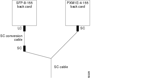
Step 2 After you have installed the first standby SFP-8-155 back card, you need to install the SC conversion cable or cables into the appropriate FRU or FRUS. Connect the LC end of the cable into the proper FRU on the SFP-8-155 card. Connect the SC end of the cable to the end of the SC cable you disconnected from the removed PXM1E-4-155 back card. The configuration should look similar to Figure 14-2.

Figure 14-2 Standby SFP-8-155 Back Card with SC Conversion Cable
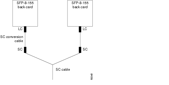
Step 3 After you have installed the second SFP-8-155 back card, install the SC conversion cable or cables into the appropriate FRU or FRUs, just as you did in Step 2. The configuration should look similar to Figure 14-3.

Figure 14-3 Both SFP-8-155 Back Cards with SC Conversion Cables

If the upgraded SFP-8-155 back cards connect to CPE that is already using LC cables, you still need to use SC conversion cables. Without the SC conversion cables, you can not do a graceful upgrade and traffic will be interrupted. This is because the CPE at the other end of the original SC connection has an LC to SC conversion cable. If you want to upgrade to a straight LC cable, you will have to disconnect the original SC conversion cable, and this will interrupt traffic.

Replacing PXM45/A or PXM45/B Cards with PXM45/C Cards

PXM45/A and PXM45/B front cards can be replaced with PXM45/C cards while the switch is operating. If a PXM45 is operating in standalone mode, all calls are interrupted until the PXM45 is replaced and the PXM45/C card is operating correctly. If the switch is using redundant PXM45s, enter the switchcc command, if necessary, to ensure that the card you want to replace is operating in standby mode. For redundant PXM45 cards, you are ready to replace the standby card as soon as the other card becomes active. You do not need to wait for the standby card to reach standby mode.


Note The PXM45/C card requires a PXM-UI-S3B back card. The PXM45/C will not run with the PXM-UI-S3 back card.


Note Before replacing PXM45 cards with PXM45/C cards, you need to upgrade all cards on the switch to Release 4.


Note If you are running CWM on your switch, you must upgrade CWM to Release 12 before replacing PXM45 cards with PXM45/C cards.


Gracefully upgrade from a Redundant PXM45 Card Set to a Redundant PXM45/C Card Set

To gracefully upgrade from a redundant PXM45 card set to a redundant PXM45/C card set, use the following procedure:


Step 1 Enter the dspcds command to verify that the current PXM45 card is running Release 4.

Step 2 If you are running CWM on your network, ensure that all workstations are running CWM Release 12.

Step 3 Enter the saveallcnf command to save the existing configuration on the current PXM45 card, and FTP that configuration file to a remote location. This ensures that you will be able to go back to your old switch configuration if you need to.

Step 4 Physically remove the standby PXM45 card set (front and back cards) from the switch on which you are performing the upgrade, and replace it with the PXM45/C card set. Replace the back cards before replacing the front cards.

Step 5 Log into the switch and configure boot parameters on the new PXM45/C card.

Step 6 Enter the dspcds command and verify that the PXM45/C comes up in the standby-ready state.

Step 7 Enter the switchcc command to witch the roles of the active and standby cards so you can upgrade the non-upgraded card in standby mode. The PXM45/C now becomes the active card, and the PXM45 becomes the standby card.

Step 8 Enter the dspcds command to verify that the PXM45/C comes up in the active-ready state.

Step 9 Physically remove the standby PXM45 from the switch on which you are performing the upgrade, and replace it with the PXM45/C.

Step 10 Enter the dspcds command and verify that the standby PXM45/C comes up in the standby-ready state.


Non-gracefully Upgrade a Single PXM45 to a PXM45/C

To non-gracefully upgrade from a single PXM45 to a PXM45/C, use the following procedure:


Step 1 Enter the dspcds command to verify that the current PXM45 card is running Release 4.

Step 2 If you are running CWM on your network, ensure that all workstations are running CWM Release 12.

Step 3 Enter the saveallcnf command to save the existing configuration on the current PXM45 card, and FTP that configuration file to a remote location. This ensures that you will be able to go back to your old switch configuration if you need to.

Step 4 Physically remove the PXM45 card set (front and back cards) from the switch on which you are performing the upgrade, and replace it with the PXM45/C card set.

Step 5 Log into the switch and configure boot parameters on the new PXM45/C card.

Step 6 Enter the dspcds command to verify that the PXM45/C comes up in the active-ready state.

Step 7 FTP the original PXM45 configuration file onto current switch. This is the file that you saved to a remote location in Step 2.

Step 8 Enter the restoreallcnf command to restore the old configurations on the current switch.

Step 9 Enter the dspcd <slotnumber> command to verify that the reserved front card is a PXM45/C. Replace <slotnumber> with the slot number of the active PXM45 card.


After you replace the PXM45 card, enter the dspcd or dsprev command to view the boot software version. If the boot software version is not correct for your switch, upgrade it as described in Appendix A, "Downloading and Installing Software Upgrades."


Note When replacing PXM45 cards with PXM45/C cards, the switch performs the same nativity check described earlier in this chapter.


Replacing AXSM Cards with AXSM/B Cards

You can replace AXSM cards with AXSM/B cards of the same type. For example, you can replace an AXSM-4-622 with and AXSM-4-622/B. The following sections describe these upgrade scenarios:

Upgrading a standalone AXSM

Upgrading an AXSM in a redundant card set

Upgrading a Standalone AXSM

You can upgrade a standalone AXSM, but all communications are interrupted during the upgrade.


Tip To avoid interrupting communications, consider installing a redundant AXSM card. You can then upgrade the AXSM using the procedure for a redundant card set.


To upgrade a standalone AXSM, use the following procedure.


Step 1 Determine if you need to upgrade the AXSM runtime software before or after the hardware upgrade. For information on the runtime software required, refer to the Release Notes for Cisco MGX 8850 (PXM1E/PXM45), Cisco MGX 8950, and Cisco MGX 8830, Software Version 4.0.00.

Step 2 Replace the standby AXSM with the AXSM/B card.


Note When replacing OC-3, OC-12, and OC-48 versions of the AXSM, you might need to change the back cards to /B versions. To determine which back cards need to be replaced, refer to the row in Table 3-9 that applies to the new AXSM/B card you are installing.


The configuration for AXSM cards is stored on the PXM45. The switch will configure the new AXSM/B card and bring it up in active mode.

Step 3 Enter the dspcd or dsprev command to verify that the AXSM/B card is using the correct boot software version.


Note The switch automatically selects and loads the correct runtime software for the AXSM based on the configuration for that slot. The switch does not automatically burn boot code for an AXSM. For instructions on upgrading boot code, see Appendix A, "Downloading and Installing Software Upgrades."


Upgrading an AXSM in a Redundant Card Set

When upgrading a redundant AXSM card set, you can complete the upgrade without interrupting established calls by using the following procedure.


Step 1 Determine if you need to upgrade the AXSM runtime software before or after the hardware upgrade. For information on the runtime software required, refer to the Release Notes for Cisco MGX 8850 (PXM1E/PXM45), Cisco MGX 8950, and Cisco MGX 8830, Software Version 4.0.00.

Step 2 Use the switchredcd command as necessary so that the AXSM card to be replaced is operating in standby mode.

Step 3 Replace the standby AXSM with the AXSM/B card.


Note When replacing OC-3, OC-12, and OC-48 versions of the AXSM, you might need to change the back cards to /B versions. To determine which back cards need to be replaced, refer to the row in Table 3-9 that applies to the new AXSM/B card you are installing.


The configuration for AXSM cards is stored on the PXM45. The switch will configure the new AXSM/B card and bring it up in standby mode.

Step 4 Enter the dspcd or dsprev command to verify that the AXSM/B card is using the correct boot software version.


Note The switch automatically selects and loads the correct runtime software for the AXSM based on the configuration for that slot. The switch does not automatically burn boot code for an AXSM. For instructions on upgrading boot code, see Appendix A, "Downloading and Installing Software Upgrades."


If you need to replace both AXSM cards in the redundant pair, repeat this procedure for the other card.


Replacing Service Modules

The procedure you use for replacing a service module depends on whether you are replacing the service module with the same type of service module or with a different type. The following sections describe the following procedures:

Replacing Service Modules with the Same Type of Service Module

Replacing Service Modules with a Different Type of Service Module

Replacing Service Modules with the Same Type of Service Module

If a service module front or back card fails, remove the old card and insert a new card of the same type in the same slot. If the card is a standalone card, all communications are interrupted. If the card is part of a redundant card set, you can replace the standby card without disrupting traffic through the active card.

The configuration for each service module is stored on the PXM. The switch automatically configures the replacement service module and starts it up. If the card is a standalone card, the card will start up as an active card. If the card is part of a redundant pair, the card will start up in standby mode.


Note The switch automatically selects and loads the correct runtime software for a service module based on the configuration for that slot. The switch does not automatically burn the boot code for a service module.


Replacing Service Modules with a Different Type of Service Module

To replace one type of service module with another type of service module, you must delete all connections, partitions, and ports, and then down all lines. This is called "decommissioning the slot," and is required, for example, when replacing an AXSM-16-T3E3 with an AXSM-8-155/B. For more information, see the " Decommissioning a Service Module Slot" section, which appears later in this chapter.

Replacing RPM Cards

If you have properly initialized an RPM card as described in the " Initializing RPM Cards" section in Chapter 9, "Preparing RPM Cards for Operation." the configuration for the RPM card is stored on the PXM hard disk.

To replace a standalone RPM card, remove the old card and insert a new card of the same type in the same slot. The switch will automatically configure the card and start it up.


Note RPM-PR and RPM-B cards are not interchangeable. When replacing an RPM-PR card, you must replace it with another RPM-PR card. If you want to change types of cards, you must first decommission the slot as described in the " Replacing PXM1E-4-155 Cards with PXM1E-8-155 Cards" section which appears later in this chapter.


To replace an RPM card that is configured for redundancy, first switch control to the standby card, then replace the card while it is operating in standby mode. If the card you are replacing has failed, there is no reason to switch cards, as the failure should have triggered a switch to the standby card. If you need to switch cards, enter the softswitch command as described in the " Switching Between Redundant RPM Cards" section in Chapter 13, "Switch Operating Procedures."


Note After you replace a card that is configured for redundancy, it starts up in standby mode. If the active card is configured to operate as a standby card for multiple RPM cards, enter a softswitch command so that the active card returns to its normal standby state.


Decommissioning a Service Module Slot

When a service module is installed and configured, the configuration is associated with a specific slot number and stored on the PXM card. If you replace the service module with another card of the same type, the new card will start operating with the established configuration. Any configuration which has been used previously on that card will be discarded, because the configuration is assigned to the slot, not to the physical card.

If you want to use a previously configured service module slot for a different type of service module, you must first decommission the slot to remove the existing configuration. Otherwise, the switch will attempt to run the old configuration on the new card, and the new card will not operate correctly.

To decommission a slot, you need to remove the existing connections, partitions, and ports. The easiest way to do this is by using the clrsmcnf -all command as described in the " Clearing a Slot Configuration" section of Chapter 13, "Switch Operating Procedures."

Decommissioning an RPM Slot

To decommission an RPM slot, you must remove all configuration items you configured for that card. You can do this by entering each command in the startup-config file with the key word no in front of it. These configuration items are described in the Cisco MGX Route Processor Module (RPM-PR) Installation and Configuration Guide and Cisco MGX Route Processor Module (RPM-XF) Installation and Configuration Guide.


hometocprevnextglossaryfeedbacksearchhelp

Posted: Thu May 31 17:07:21 PDT 2007
All contents are Copyright © 1992--2007 Cisco Systems, Inc. All rights reserved.
Important Notices and Privacy Statement.