|
|

Table Of Contents
Provisioning PXM1E Communication Links
Quickstart Provisioning Procedures
ATM Trunk Configuration Quickstart
PNNI UNI Port Configuration Quickstart
SPVC and SPVP Configuration Quickstart
PNNI Virtual Trunk Configuration Quickstart
BPX PNNI Trunk Configuration Quickstart
AINI Link Configuration Quickstart
IISP Link Configuration Quickstart
XLMI Link Configuration Quickstart
Cisco IGX Feeder to Cisco MGX 8850 Configuration Quickstart
PNNI UNI Port Configuration Quickstart
General PXM1E Configuration Procedures
Partitioning Port Resources Between Controllers
Selecting the Port Signaling Protocol
Assigning Static ATM Addresses to Destination Ports
Configuring PXM1E Line Clock Sources
Configuring Point-to-Multipoint SPVCs and SPVPs
Defining Destination Addresses for Static Links
Configuring Inverse Multiplexing for ATM
Adding an IMA Link to an IMA Group
Configuring a Connection to an IGX Feeder
Connecting a PXM1E Card to a UXM Card on an IGX feeder
Provisioning PXM1E Communication Links
This chapter describes how to add logical ports and virtual connections to physical lines. This chapter explains how to provision the link and connection types listed in Table 11-1.
1 SVC = switched virtual circuits
2 SPVC = soft permanent virtual circuit
3 AINI = ATM Inter-Network Interface
4 IISP = Interim Inter-Switch Protocol
5 ILMI = Extended Link Management Interface
The configuration differences between these types of connections are often as simple as an additional command or a different set of command options. To eliminate redundancy and help experienced users complete configuration procedures quickly, this chapter uses configuration quickstarts and task descriptions to explain how to configure connections.
The first time you configure a connection type, use the quickstart procedure to see the order of tasks to complete, and then read the task descriptions for detailed instructions.
Note
For all commands in this chapter, refer to the Cisco MGX 8850 (PXM1E/PXM45), Cisco MGX 8950, and Cisco MGX 8830 Command Reference for detailed information.
Note
Quickstart Provisioning Procedures
The following sections present abbreviated procedures that you can use to provision connections.
ATM Trunk Configuration Quickstart
ATM trunks connect the switch to other ATM switches in the core ATM network. The quickstart procedure in this section provides a summary of the tasks required to configure ATM trunks on Cisco MGX switches. This procedure is a quick reference for those who have previously configured these types of connections.
Note
Step 1
username
<password>
Start a configuration session.
Note
Step 2
Prepare PXM1E cards and lines as described in Chapter 4, "Preparing PXM1E Lines for Communication."
Remember to select the appropriate card SCT for the controller or controllers you are using.
Step 3
addport <options>
Related commands:
dspports
Add and configure ATM ports. This step establishes ATM communications between two ATM devices.
Specify NNI for interswitch trunks.
See the " Adding ATM Ports" section later in this chapter.
Step 4
addpart <options>
Related commands:
dspparts
dsppart
cnfpart
Assign trunk resources to PNNI controllers. This step can assign all the trunk bandwidth to a single controller, or it can assign portions of the trunk bandwidth to each controller.
See the " Partitioning Port Resources Between Controllers" section later in this chapter.
Step 5
dnpnport <portid>
cnfpnportsig <options>
uppnport <portid>
Related commands:
dsppnports
dsppnport <portid>
dsppnportsig <portid>
Define the signaling protocol used on the trunk. The default signaling protocol is UNI Version 3.1. Specify pnni10 for PNNI trunks.
See the " Selecting the Port Signaling Protocol" section later in this chapter.
Step 6
dsppnni-link
dsppnni-neighbor
When both ends of the link are configured, verify the PNNI communications between the two ends. In the dsppnni-link report, there should be an entry for the port for which you are verifying communications. The Hello state reported should be twoWayInside, and the Remote node ID should display the remote node ATM address after the second colon.
See the " Verifying PNNI Trunk Communications" section later in this chapter.
Step 7
upilmi <ifNum> <partId>
cnfilmi <options>
Related commands:
dspports
dspilmis
This step is optional. Configure and start ILMI on trunks where you want to support Cisco WAN Manager or use ILMI features.
See the " Configuring ILMI on a Port" section later in this chapter.
After you configure an PXM1E trunk, the trunk is ready to support SVCs. You can also create SPVCs and SPVPs between CPE at each end of the trunk as described in " Configuring SPVCs and SPVPs," which appears later in this chapter.
PNNI UNI Port Configuration Quickstart
ATM UNI ports connect the switch to ATM end devices, which serve as the boundary between the ATM network and other communications paths or networks. Typical end devices include ATM routers and multiservice concentrators. UNI signaling is used between the end system (CPE) and the PNNI network for requesting calls.
The quickstart procedure in this section provides a summary of the tasks required to configure UNI ports on Cisco MGX switches. This procedure is provided as an overview and as a quick reference for those who have previously configured UNI ports.
Note
Step 1
username
<password>
Start a configuration session.
Note
Step 2
—
Prepare PXM1E cards and lines as described in Chapter 4, "Preparing PXM1E Lines for Communication."
Remember to select the appropriate card SCT for the controller or controllers you are using.
Step 3
addport <options>
Related commands:
dspports
Add and configure ATM ports. This step establishes ATM layer two communications between two ATM devices.
Specify UNI for ATM lines.
See the " Adding ATM Ports" section later in this chapter.
Step 4
addpart <options>
Related commands:
dspparts
dsppart
cnfpart
Assign line resources to the PNNI controllers. This step can assign all the line bandwidth to a single controller, or it can assign portions of the line bandwidth to each controller.
See the " Partitioning Port Resources Between Controllers" section later in this chapter.
Step 5
dnpnport <portid>
Bring down the port so it can be configured. The next three steps require this step.
Step 6
cnfpnportsig <options>
Related commands:
dsppnports
dsppnport <portid>
dsppnportsig <portid>
Define the signaling protocol used on the line. The default signaling protocol for UNI lines is UNI Version 3.1.
Specify uni30, uni31, or uni40.
See the " Selecting the Port Signaling Protocol" section later in this chapter.
Step 7
cnfaddrreg <portid> no
addaddr <options>
Related commands:
dsppnports
dspatmaddr <portid>
deladdr <options>
Configure static ATM addresses for ports that require them.
See the " Assigning Static ATM Addresses to Destination Ports" section later in this chapter.
Step 8
addprfx <portid> atm-prefix
Related commands:
cnfaddrreg <portid> yes
dspprfx <portid>
If dynamic addressing is to be used on a port, define an ATM address prefix that ILMI can use when assigning addresses.
See the " Configuring ILMI Dynamic Addressing" section later in this chapter.
Step 9
uppnport <portid>
Bring up port after configuration is complete.
Step 10
upilmi <ifNum> <partId>
cnfilmi <options>
Related commands:
dspports
dspilmis
Configure and start ILMI on the port. This step is required for dynamic addressing and the ILMI automatic configuration feature. Otherwise, it is optional.
See the " Configuring ILMI on a Port" section later in this chapter.
SVC Configuration Quickstart
Switched virtual circuits (SVCs) are the solution for on-demand connections. They are set up as needed and torn down when no longer needed. To enable this dynamic activity, SVCs use signaling. End systems request connectivity to other end systems and, provided that the requested services are available, the connection is set up at the time of the request. When idle, an SVC is taken down to save network bandwidth.
Cisco MGX 8850 (PXM1E) and Cisco MGX 8830 switches can use the PNNI protocol to determine how to set up SVCs through the network. Because the switch automatically sets up SVCs, you do not have to configure SVC routes. However, the switch must be configured correctly before it can set up SVCs. The following quickstart procedure summarizes the tasks required to enable SVC communications. With the exception of CPE configuration, all these tasks are described in this chapter.
Note
Step 1
See the " ATM Trunk Configuration Quickstart" section earlier in this chapter.
Configure the trunks that link the switches through which the ATM end stations connect. Be sure to add the PNNI controller on each switch and select that controller when partitioning trunks.
Step 2
dsppnni-reachable-addr network
Verify connectivity between the node pairs that will host SVCs.
See the " Verifying End-to-End PNNI Communications" section later in this chapter.
Step 3
See the " PNNI UNI Port Configuration Quickstart" section earlier in this chapter.
Configure UNI ports for the ATM end stations at each end of the SVC, and assign either static or dynamic addressing to each line. Be sure to add the PNNI controller on each switch and select that controller when partitioning trunks.
Step 4
See the CPE documentation.
Configure CPE devices for communications with the switch through the UNI ports configured in the previous step.
Step 5
dsppncons
This optional step displays the SVC connections that are operating.
See the " Displaying SVCs" section in Chapter 13, "Switch Operating Procedures."
It is beyond the scope of this guide to describe how to configure each model of the CPE to communicate with the switch. To complete this configuration, you will need to learn the capabilities of the CPE and the switch and define a set of communications parameters that are supported by both devices. For example, the Cisco MGX switches support UNI 3.1 communications, but if the CPE does not, you must select a signaling protocol (such as UNI 3.0) that is supported by both devices.
Once all the requirements have been met for SVC connections, CPE devices can establish SVC connections to other CPE devices on the same switched network.
SPVC and SPVP Configuration Quickstart
A soft permanent virtual circuit (SPVC) is a permanent virtual circuit (PVC) that can be rerouted using the Private Network-to-Network Interface (PNNI) Version 1.0 protocol. As with PVCs, SPVCs are full-time connections. A PVC, however, uses a predefined circuit path and will fail if the path is interrupted. Using the PNNI protocol, SPVCs can be rerouted to avoid failed communication links or to use links that offer better bandwidth.
An SPVP is a permanent virtual path that can be rerouted using the PNNI Version 1.0 protocol. The difference between an SPVC and an SPVP is that the SPVP supports multiple virtual circuits, whereas a SPVC is by definition a single virtual circuit. As with SPVCs, when an SPVP fails, PNNI can determine if an alternate route exists and reroute the connection.
The quickstart procedure in this section provides a summary of the tasks required to configure SPVCs and SPVPs on Cisco MGX 8850 (PXM1E) and Cisco MGX 8830 switches. This procedure is provided as an overview and as a quick reference for those who have previously configured these types of connections.
PNNI Virtual Trunk Configuration Quickstart
Virtual trunks are introduced in the "Multiservice Edge Aggregation" section in "Preparing for Configuration." Figure 11-1 shows illustrates how a virtual trunk is configured.
Figure 11-1 Virtual Trunk Topology
Figure 11-1 shows an example of configuration data that you can use when following the quickstart procedure below. Note that the single trunk between Private Switch A and Edge Switch A hosts two virtual trunks, which terminate at Virtual Network-to-Network Interface (VNNI) ports 10:1.2:2 and 10:1.2:7. The switch supports up to 256 VNNI ports on a UNI link and up to 4096 VNNI ports on an NNI link.
To set up a virtual trunk, the following tasks have to be completed:
•
•
The Cisco MGX switches support:
•
•
•
The following quickstart procedure provides a summary of the tasks required to configure virtual trunks on Cisco MGX switches. This procedure is provided as an overview and as a quick reference for those who have previously configured these types of connections.
Step 1
username
<password>
Start a configuration session on a Cisco MGX 8850 (PXM1E) or Cisco MGX 8830 switch. This will be the local routing switch that connects to the feeder.
Note
Step 2
Prepare PXM1E cards and lines as described in Chapter 4, "Preparing PXM1E Lines for Communication."
Remember to select the appropriate card SCT for the controller or controllers you are using.
Step 3
addport <options>
or
addimagrp <options>
addimalink <options>
addimaport <options>
Related commands:
dspports
Configure the virtual trunk end ports at the private switches. Select interface type 3 for VNNI.
For standard port configuration, see the " Adding ATM Ports" section later in this chapter.
If you are configuring IMA on this port, see the " Configuring Inverse Multiplexing for ATM" section later in this chapter.
Step 4
addpart <options>
Related commands:
dspparts
dsppart
cnfpart
Configure the virtual trunk partitions at the private switches. Enter the same VPI number for the minVpi and maxVpi parameters. This number becomes the VPI number for the trunk.
See the " Partitioning Port Resources Between Controllers" section later in this chapter.
Note
Step 5
dnpnport <portid>
cnfpnportsig <options>
uppnport <portid>
Related commands:
dsppnports
dsppnport <portid>
dsppnportsig <portid>
Configure the virtual trunk signaling at the private switches. Select PNNI signaling by setting the -nniver option to pnni10.
pop20two.7.PXM.a > cnfpnportsig <portid> -nniver pnni10See the " Selecting the Port Signaling Protocol" section later in this chapter.
Step 6
addport <ifnum>
Related commands:
dspports
Add and configure the virtual trunk end ports at each core edge node. Specify interface type 1 for UNI or 2 for NNI.
See the " Adding ATM Ports" section later in this chapter.
Step 7
addpart
Related commands:
dspparts
dspparts
cnfpart
Configure the virtual trunk partitions at each core edge node. Use a VPI range that includes all VPI numbers set for virtual trunks on this line at the private switch.
See the " Partitioning Port Resources Between Controllers"section in this chapter.
Step 8
dnpnport
cnfpnportsig
uppnport
Related commands:
dsppnports
dsppnport
dsppnportsig
Configure the virtual trunk signaling at each core edge node. Select no trunk signaling by setting the -univer option (UNI ports) to none or the -nniver option (NNI ports) to none.
See the " Selecting the Port Signaling Protocol" section later in this chapter.
Step 9
addcon <options>
Related commands:
dspcon
dspcons
For each virtual trunk, configure an SPVP between the virtual trunk ports at each edge of the core network. See the " Configuring SPVCs and SPVPs" section in this chapter.
Step 10
dsppnni-reachable-addr network
Verify PNNI connectivity between the two nodes that will host the virtual trunk end points.
See the " Verifying End-to-End PNNI Communications"section in this chapter.
BPX PNNI Trunk Configuration Quickstart
When the Cisco SES PNNI controller is attached to a Cisco BPX switch, the BPX switch can participate in a PNNI network with Cisco MGX switches. The connection between an Cisco MGX 8850 (PXM1E) switch and a BPX switch is a trunk between an PXM1E card in the MGX switch and a BXM card in the BPX. For instructions on configuring the BXM end of the trunk, refer to the Cisco SES product documentation. This section describes how to configure the PXM1E end of the trunk.
The procedure for configuring the PXM1E end of the trunk is similar to the general procedure for configuring PXM1E trunks. The following quickstart procedure is customized for setting up BPX PNNI trunks.
Note
Caution
Step 1
username
<password>
Start a configuration session.
Note
Step 2
Prepare PXM1E cards and lines as described in Chapter 4, "Preparing PXM1E Lines for Communication."
Step 3
addport <options>
Related commands:
dspports
Add and configure ATM ports. This step establishes ATM communications between two ATM devices.
Specify NNI for interswitch trunks.
See the " Adding ATM Ports"section later in this chapter.
Step 4
addpart <options>
Related commands:
dspparts
dsppart
cnfpart
Add and configure a PNNI partition for the trunk. This step reserves trunk resources for the PNNI controller.
See the " Partitioning Port Resources Between Controllers" section later in this chapter.
Step 5
dnpnport <portid>
cnfpnportsig <options>
uppnport <portid>
Related commands:
dsppnports
dsppnport <portid>
dsppnportsig <portid>
Define the signaling protocol used on the trunk. The default signaling protocol is UNI Version 3.1, so you must change the signaling protocol to pnni10. For example:
pop20two.7.PXM.a > cnfpnportsig <portid> -nniver pnni10See the " Selecting the Port Signaling Protocol" section later in this chapter.
Step 6
upilmi <ifNum> <partId>
cnfilmi <options>
Related commands:
dspports
dspilmis
Configure and start ILMI on the trunk. ILMI is required on the BXM end of the trunk, so it must be enabled on the PXM1E side too.
See the " Configuring ILMI on a Port" section later in this chapter.
Step 7
dsppnni-link
dsppnni-neighbor
When both ends of the link are configured, verify the PNNI communications between the two ends. In the dsppnni-link report, there should be an entry for the port for which you are verifying communications. The Hello state reported should be twoWayInside and the Remote node ID should display the remote node ATM address after the second colon.
See the " Verifying PNNI Trunk Communications" section later in this chapter.
After you configure a BPX PNNI trunk, the trunk is ready to support SVCs. You can also create SPVCs and SPVPs between CPE at each end of the trunk as described in the " Configuring SPVCs and SPVPs" section later in this chapter.
AINI Link Configuration Quickstart
The quickstart procedure in this section provides a summary of the tasks required to configure ATM Inter-Network Interface (AINI) links on Cisco MGX switches. This procedure is provided as an overview and as a quick reference for those who have previously configured these types of connections.
Step 1
username
<password>
Start a configuration session.
Note
Step 2
Prepare PXM1E cards and lines as described in Chapter 4, "Preparing PXM1E Lines for Communication."
Remember to select the appropriate card SCT for the controller or controllers you are using.
Step 3
addport <options>
Related commands:
dspports
Add and configure ATM ports. This step establishes ATM communications between two ATM devices.
Specify NNI for interswitch trunks.
See the " Adding ATM Ports" section later in this chapter.
Step 4
addpart <options>
Related commands:
dspparts
dsppart
cnfpart
Assign trunk resources to the PNNI controller. This step can assign all the trunk bandwidth to a single controller, or it can assign portions of the trunk bandwidth to each controller.
See the " Partitioning Port Resources Between Controllers" section later in this chapter.
Step 5
dnpnport <portid>
cnfpnportsig <options>
uppnport <portid>
Related commands:
dsppnports
dsppnport <portid>
dsppnportsig <portid>
Define the signaling protocol used at each end of the AINI link. The default signaling protocol is UNI Version 3.1. Specify aini for AINI trunks.
For example:
8850_LA.7.PXM.a > cnfpnportsig 1:1.1:1 -nniver ainiSee the " Selecting the Port Signaling Protocol" section later in this chapter.
Step 6
addaddr <options>
Add destination addresses to each end of the trunk.
See the " Defining Destination Addresses for Static Links" section later in this chapter.
Step 7
addaddr <options>
Add static addresses to destination ports. This step is required when addresses are not dynamically assigned to the CPE at the destination ports.
See the " Assigning Static ATM Addresses to Destination Ports" section later in this chapter.ater in this chapter.
IISP Link Configuration Quickstart
The quickstart procedure in this section provides a summary of the tasks required to configure Interim Inter-Switch Protocol (IISP) links on Cisco MGX switches. This procedure is provided as an overview and as a quick reference for those who have previously configured these types of connections.
Note
Step 1
username
<password>
Start a configuration session.
Note
Step 2
Prepare PXM1E cards and lines as described in Chapter 4, "Preparing PXM1E Lines for Communication."
Remember to select the appropriate card SCT for the controller or controllers you are using.
Step 3
addport <options>
Related commands:
dspports
Add and configure ATM ports. This step establishes ATM communications between two ATM devices.
Specify NNI for interswitch trunks.
See the " Adding ATM Ports," section later in this chapter.
Step 4
addpart <options>
Related commands:
dspparts
dsppart
cnfpart
Assign trunk resources to the PNNI controller. This step can assign all the trunk bandwidth to a single controller, or it can assign portions of the trunk bandwidth to each controller.
See the " Partitioning Port Resources Between Controllers" section later in this chapter.
Step 5
dnpnport <portid>
cnfpnportsig <options>
uppnport <portid>
Related commands:
dsppnports
dsppnport <portid>
dsppnportsig <portid>
Define the signaling protocol used at each end of the IISP link. The default signaling protocol is UNI Version 3.1. Specify either iisp30 or iisp31 for IISP trunks.
For example:
mgx8830a.1.PXM.a > cnfpnportsig 1:1.1:1 -nniver iisp31See the " Selecting the Port Signaling Protocol" section later in this chapter.
Step 6
addaddr <options>
Add destination addresses to each end of the trunk.
See the " Defining Destination Addresses for Static Links" section later in this chapter.
Step 7
addaddr <options>
Add static addresses to destination ports. This step is required when addresses are not dynamically assigned to the CPE at the destination ports.
See the " Assigning Static ATM Addresses to Destination Ports" section later in this chapter.
XLMI Link Configuration Quickstart
An Extended Link Management Interface (XLMI) link joins a PNNI network with an AutoRoute network. After you establish an XLMI link, you can configure connections that link CPE in the PNNI network with CPE in the AutoRoute network. The interconnection of PNNI and AutoRoute networks enables network expansion beyond the limits of AutoRoute and facilitates a gradual migration from an all AutoRoute network to an all PNNI network.
To establish an XLMI link, you need to the following tasks:
1.
2.
3.
The quickstart procedure in this section describes how to configure an PXM1E port to support an XLMI link, and references the instructions for creating a connection between the PNNI and AutoRoute networks. Before you begin configuration, consider the following guidelines and limitations:
•
•
•
•
•
•
•
–
–
–
The following quickstart procedure provides a summary of the tasks required to configure XLMI links on Cisco MGX 8850 (PXM1E) and Cisco MGX 8830 switches.
Step 1
username
<password>
Start a configuration session.
Note
Step 2
—
Prepare PXM1E cards and lines as described in Chapter 4, "Preparing PXM1E Lines for Communication."
Remember to select the appropriate card SCT for the controller or controllers you are using.
Step 3
addport <options>
Related commands:
dspports
Add and configure ATM ports. This step establishes ATM communications between two ATM devices.
The PXM1E cards supports XLMI on UNI or NNI ports.
See the " Adding ATM Ports"section later in this chapter.
Step 4
addpart <options>
Related commands:
dspparts
dsppart
cnfpart
Assign port resources to the PNNI controller. This step can assign all the port bandwidth to a single controller, or it can assign portions of the port bandwidth to each controller.
See the " Partitioning Port Resources Between Controllers" section later in this chapter.
Step 5
addlmi <interface> <type>
Related commands:
dsplmi <interface>
Add LMI to the port. For example:
M8850_NY.6.PXM1E.a > addlmi 2 2Replace the type variable with 2 for XLMI links. (Type 1 selects feeder operation.)
Step 6
dnpnport <portid>
Related commands:
dsppnports
dsppnport <portid>
Bring down the port so it can be configured.
Step 7
cnfpnportsig <options>
Related commands:
dsppnport <portid>
dsppnportsig <portid>
Define the signaling protocol used for the port. The default signaling protocol is UNI Version 3.1. Specify enni for XLMI trunks.
For example:
mgx8830a.1.PXM.a > cnfpnportsig 1:1.1:1 -nniver enniSee the " Selecting the Port Signaling Protocol" section later in this chapter.
Step 8
uppnport <portid>
Related commands:
dsppnports
dsppnport <portid>
Bring up the configured port.
Step 9
—
If you are using CWM to manage your networks, the XLMI link should be ready to use. Use CWM to add a connection from a destination in the AutoRoute network to a destination in the PNNI network.
Step 10
addcon <options>
If you are not using CWM to manage your networks, add a connection from the XLMI link endpoint on the PXM1E to a destination on the PNNI network.
Note
See the " Configuring SPVCs and SPVPs" section later in this chapter.
Note
Step 11
—
If you are not using CWM to manage your networks, add a connection from the XLMI link endpoint on the BXM to a destination on the AutoRoute network.
Note
For more information, refer to the Cisco BPX 8600 Series Installation and Configuration guide.
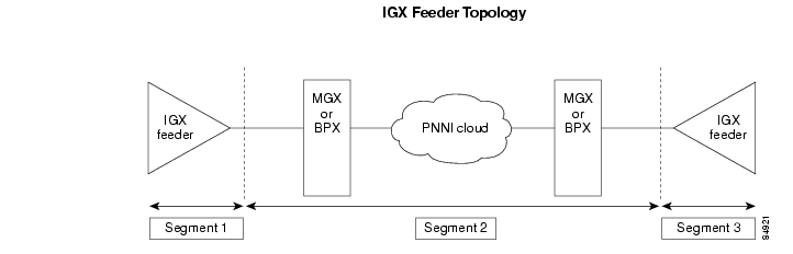
Cisco IGX Feeder to Cisco MGX 8850 Configuration Quickstart
The quickstart procedure in this section provides a summary of the tasks required to configure a feeder between a Cisco MGX 8850 (PXM1E) or Cisco MGX 8830 switch, and a Cisco IGX 8400 switch. This procedure is provided as an overview and as a quick reference for those who have previously configured these types of connections.
Step 1
username
<password>
Start a configuration session with the active PXM1E card on a Cisco MGX 8850 (PXM1E) or Cisco MGX 8830 switch.
Note
Step 2
upln
addport
or
addimagrp
addimalnk
addimaport <options>
Related commands:
dspports.
Create an interface between the PXM1E card on a Cisco MGX 8850 (PXM1E) or a Cisco MGX 8830, and the UXM card on a Cisco IGX 8400.
For standard port configuration, see the " Adding ATM Ports" section later in this chapter.
If you are configuring IMA on this port, see the " Configuring Inverse Multiplexing for ATM" section later in this chapter.
Step 3
addlmi
Designate the interface as a feeder.
Step 4
dnpnport <portid>
cnfpnportsig <options>
uppnport <portid>
Related commands:
dsppnports
dsppnport <portid>
dsppnportsig <portid>
Define the signaling protocol used at each end of the trunk.
For example:
mgx8830a.1.PXM.a > cnfpnportsig 1:1.1:1 -nniver iisp31See the " Selecting the Port Signaling Protocol" section later in this chapter.
Step 5
username
<password>
Start a configuration session with the UXM card on a Cisco IGX 8400 switch.
Note
Step 6
cnfswfunc
uptrk
cnftrk
Configure the trunk on the IGX switch. The configuration on the UXM end of the trunk must match the configuration on the PXM1E end of the trunk.
PNNI UNI Port Configuration Quickstart
ATM UNI ports connect the switch to ATM end devices, which serve as the boundary between the ATM network and other communications paths or networks. Typical end devices include ATM routers and multiservice concentrators. UNI signaling is used between the end system (CPE) and the PNNI network for requesting calls.
The quickstart procedure in this section provides a summary of the tasks required to configure UNI ports on Cisco MGX 8850 (PXM1E) and Cisco MGX 8830 switches. This procedure is provided as an overview and as a quick reference for those who have previously configured UNI ports.
Note
Step 1
username
<password>
Start a configuration session.
Note
Step 2
—
Prepare PXM1E cards and lines as described in Chapter 4, "Preparing PXM1E Lines for Communication."
Remember to select the appropriate card SCT for the controller or controllers you are using.
Step 3
addport <options>
Related commands:
dspports
Add and configure ATM ports. This step establishes ATM layer two communications between two ATM devices.
Specify UNI for ATM lines.
See the " Adding ATM Ports" section later in this chapter.
Step 4
addpart <options>
Related commands:
dspparts
dsppart
cnfpart
Assign line resources to the PNNI controllers. This step can assign all the line bandwidth to a single controller, or it can assign portions of the line bandwidth to each controller.
See the " Partitioning Port Resources Between Controllers" section later in this chapter.
Step 5
dnpnport <portid>
Bring down the port so it can be configured. The next three steps require this step.
Step 6
cnfpnportsig <options>
Related commands:
dsppnports
dsppnport <portid>
dsppnportsig <portid>
Define the signaling protocol used on the line. The default signaling protocol for UNI lines is UNI Version 3.1.
Specify uni30, uni31, or uni40.
See the " Selecting the Port Signaling Protocol" section later in this chapter.
Step 7
cnfaddrreg <portid> no
addaddr <options>
Related commands:
dsppnports
dspatmaddr <portid>
deladdr <options>
Configure static ATM addresses for ports that require them.
See the " Assigning Static ATM Addresses to Destination Ports" section later in this chapter.
Step 8
addprfx <portid> atm-prefix
Related commands:
cnfaddrreg <portid> yes
dspprfx <portid>
If dynamic addressing is to be used on a port, define an ATM address prefix that ILMI can use when assigning addresses.
See the " Configuring ILMI Dynamic Addressing" section later in this chapter.
Step 9
uppnport <portid>
Bring up port after configuration is complete.
Step 10
upilmi <ifNum> <partId>
cnfilmi <options>
Related commands:
dspports
dspilmis
Configure and start ILMI on the port. This step is required for dynamic addressing and the ILMI automatic configuration feature. Otherwise, it is optional.
See the " Configuring ILMI on a Port" section later in this chapter.
General PXM1E Configuration Procedures
This section describes the following general procedures for configuring PXM1E card communications:
•
•
•
Adding ATM Ports
The previous chapter described how to bring up physical lines by specifying the correct line port number. The line ports correspond to line connectors on the switch back cards. Bringing up a line establishes minimal connectivity between two nodes. When you add an ATM port to a line, you enable ATM communications over the line.
Each line can support UNI or NNI ports. UNI ports are used for lines that connect to PBXs, ATM routers, and other ATM devices that connect to the core ATM network through the switch. NNI ports are used for trunks that connect to other core ATM network devices, such as another Cisco MGX 8850 (PXM1E/PXM45) switch.
You must configure one ATM port for each line or trunk to enable ATM communications over that link. You define the port type when you add the ATM port to the line or trunk. The port type can be one of the following:
•
•
•
•
•
•
To add an ATM port to a line, use the following procedure.
Step 1
Step 2
mgx8830a.1.PXM.a > dsplns
Tip
Step 3
mgx8830a.1.PXM.a > dspportsThis command displays all ports on the PXM1E card in the ifNum (interface number) column. The interfaces listed include UNI, NNI, VUNI, VNNI, EVUNI, and EVNNI ports. Pay attention to the port numbers already in use. When you add a port, you must specify a port number that is unique on the PXM1E card. For example, if port number 2 is assigned to line 2.1 (bay 2, line 1), you cannot use port 2 on any other line on that PXM1E card.
Step 4
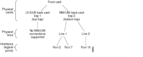
mgx8830a.1.PXM.a > addport <ifNum> <bay.line> <guaranteedRate> <maxRate> <sctID> <ifType>
[vpi <vpi>] [-minvpi <minvpi>] [-maxvpi <maxvpi>]
Table 11-2 lists the parameter descriptions for adding ports. Figure 11-2 shows the relationship between logical interface numbers and physical lines.
Figure 11-2 Relationship Between Cards, Bays, Lines, and Logical Interface Numbers
The following example command defines a line port as a UNI line:
mgx8830a.1.PXM.a > addport 1 2.1 96000 96000 1 1The following example command defines a line port as an NNI trunk:
mgx8830a.1.PXM.a > addport 2 2.1 3622 3622 52 2Step 5
mgx8830a.1.PXM.a > dspportsThis command displays all configured ports on the PXM1E card. Port numbers are listed in the ifNum (interface number) column. If you want to view information on a particular port, note the number of that port.
Step 6
mgx8830a.1.PXM.a > dspport <ifNum>Replace <ifNum> with the number assigned to the port during configuration. The following example shows the report for this command:
mgx8830a.1.PXM.a > dspport 1Interface Number : 1Line Number : 2.3 IMA Grp Number : N/AAdmin State : Up Operational State : UpGuaranteed bandwidth(cells/sec): 353207 Number of partitions : 1Maximum bandwidth(cells/sec) : 353207 Number of SPVC : 0ifType : NNI Number of SPVP : 0VPI number (VNNI, VUNI) : 0 Number of SVC : 3MIN VPI (EVNNI, EVUNI) : 0 MAX VPI (EVNNI, EVUNI): 0SCT Id (Conf./InUse) : 0/0=Def, F4 to F5 Conversion : Disabled
Tip
Partitioning Port Resources Between Controllers
After you add a line or trunk port, you need to define how the port resources are used by the PNNI controller. You can assign the following resources to controllers:
•
•
•
•
Note
The port resources are defined as a group in a controller partition, which is dedicated to a single port controller. You must define one controller partition for each controller type you want to support, and you must configure one resource partition for each port that uses a controller.
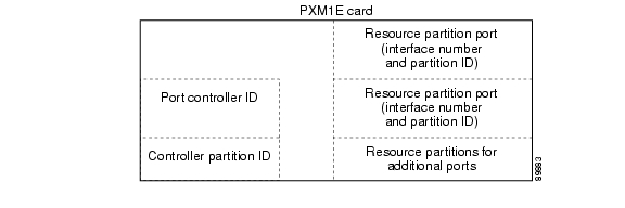
Figure 11-3 presents a simplified view of the relationship between the port controller, controller partition, and resource partitions on MGX switches with PXM1E controllers. Because a PXM1E controller supports ATM connections on Cisco MGX 8850 (PXM1E) and Cisco MGX 8830 switches, you can configure resource partitions directly on the PXM1E card.
Figure 11-3 Relationship of Port Controller, Controller Partition, and Resource Partitions
Figure 11-3 shows that the single controller partition connects to the port controller and to the resource partitions. Note that the port controller and the controller partition both reside on the PXM1E card.
After you create a port, you must create a resource partition for that port, select the PNNI controller, and define which ATM resources the port will use. You do not have to create the controller partition, as it is automatically created when you create the first resource partition. It is important that the same controller partition, and therefore the same partition ID, be used for all resource partitions of the same type on the same PXM1E card. For example, the controller is identified by the controller ID and the controller partition is identified by the partition ID. The resource partitions are identified by specifying the partition ID in combination with the port ID (interface number).
Note
To create a resource partition for a port, use the following procedure.
Step 1
Note
Step 2
mgx8830a.1.PXM.a > dspportsThis command displays all ports on the PXM1E card in the ifNum (interface number) column.
Step 3
mgx8830a.1.PXM.a > addpart <ifNum> <partId> <ctrlrId> <egrminbw> <egrmaxbw> <ingminbw>
<ingmaxbw> <minVpi> <maxVpi> <minVci> <maxVci> <minConns> <maxConns>
Table 11-3 describes the parameters for this command.
Table 11-3 Parameters for the addpart Command
ifNum
Interface number or port number. This number identifies the port this resource partition configures. Enter the interface number that was assigned to the port when it was configured (see the " Adding ATM Ports" section earlier in this chapter).
partId
Partition identification number. Enter a number in the range of 1 to 20. On an PXM1E card, this number must be the same for all ports that use the same controller type. For example, if you assign the number 2 to the PNNI controller on any port, the partition ID for the PNNI controller on all other ports must be set to 2.
ctrlrId
Controller identification number. Enter the number 2 to specify the PNNI controller.
For more information, refer to " Adding the PNNI Controller" in Chapter 3, "Configuring General Switch Features."
egrminbw
Egress minimum bandwidth. Enter the minimum percentage of the outgoing port bandwidth that you want assigned to the specified controller. One percent is equal to .0001 units. For example, an <egrminbw> of 250000 = 25%. The sum of the minimum egress bandwidth settings for PNNI must be 100% or less, and must be less than the sum of the egrmaxbw settings.
egrmaxbw
Egress maximum bandwidth. Enter the maximum percentage of the outgoing port bandwidth that you want assigned to the controller. One percent is equal to .0001 units. For example, an <egrmaxbw> of 1000000 = 100%. The sum of the maximum egress bandwidth settings for PNNI can exceed 100%, and must be more than the sum of the egrminbw settings. Available bandwidth above the minimum bandwidth settings is allocated to the operating controllers on a first-requested, first-served basis until the maximum bandwidth setting is met or there is insufficient bandwidth to meet the request.
ingminbw
Ingress minimum bandwidth. Enter the minimum percentage of the incoming port bandwidth that you want assigned to the controller. One percent is equal to .0001 units. For example, an <ingminbw> of 500000 = 50%. The sum of the minimum ingress bandwidth settings for PNNI must be 100% or less, and must be less than the sum of the ingmaxbw settings.
ingmaxbw
Ingress maximum bandwidth. Enter the maximum percentage of the incoming port bandwidth that you want assigned to the controller. One percent is equal to .0001 units. For example, an <ingmaxbw> of 750000 = 75%. The sum of the maximum ingress bandwidth settings for PNNI can exceed 100%, and must be more than the sum of the ingminbw settings. Available bandwidth above the minimum bandwidth settings is allocated to the operating controllers on a first-request, first-served basis until the maximum bandwidth setting is met or there is insufficient bandwidth to meet the request.
minVpi
Minimum VPI. For NNI, the range is 0-4095. For UNI, the range is 0-255.
maxVpi
Maximum VPI in the range 0-4095 for an NNI. For a UNI, the range is 0-255. The maxvpi cannot be less than the minvpi.
minVci
The minimum VCI has a range of 1-65535.
maxVci
Maximum VPI in the range 0-4095 for an NNI. For a UNI, the range is 0-255. The maxvpi cannot be less than the minvpi.
minConns
Specifies the guaranteed number of connections. On the PXM1E UNI/NNI, the ranges vary according to the line types, as follows:
•
•
maxConns
Specifies the guaranteed number of connections. On the PXM1E UNI/NNI, the ranges vary according to the line types, as follows:
•
•
Step 4
mgx8830a.1.PXM.a > dsppartsStep 5
mgx8830a.1.PXM.a > dsppart <ifNum> <partId>Table 11-3 describes the parameters for this command.
The following example shows the report provided by the dsppart command.
mgx8830a.1.PXM.a > dsppart 1 1Interface Number : 1Partition Id : 1 Number of SPVC: 0Controller Id : 2 Number of SPVP: 0egr Guaranteed bw(.0001percent): 1000000 Number of SVC : 0egr Maximum bw(.0001percent) : 1000000ing Guaranteed bw(.0001percent): 1000000egr Maximum bw(.0001percent) : 1000000min vpi : 0max vpi : 4095min vci : 1max vci : 65535guaranteed connections : 10000maximum connections : 10000
Note
Note
Selecting the Port Signaling Protocol
The default signaling protocol for all new ports is UNI Version none. If you plan to use this protocol on a line, you can accept this default and skip this section. However, if you plan to use a different protocol on the line, such as NNI or PNNI, you must select the correct protocol using the following procedure.
Step 1
Step 2
mgx8830a.1.PXM.a > dsppnportsStep 3
mgx8830a.1.PXM.a > dnpnport <portid>A port is automatically brought up when you add it. You must bring down the port before you can change the port signaling protocol. Replace <portid> using the format slot[:bay].line[:ifNum]. Table 11-4 describes these parameters.
Step 4
mgx8830a.1.PXM.a > dsppnportsSummary of total connections(p2p=point to point,p2mp=point to multipoint,SpvcD=DAX spvc,SpvcR=Routed spvc)Type #Svcc: #Svpc: #SpvcD: #SpvpD: #SpvcR: #SpvpR: #Ctrl #Total:p2p: 0 0 0 0 1 0 0 1p2mp: 0 0 0 0 0 0 0 0Total(User cons) = 1/27000, Total(Ctrl cons) = 0Total=1Summary of total SPVC endpoints(P=Persistent, NP=Non-Persistent)Type #SpvcR-P #SpvcR-NP #SpvpR-P #SpvpR-NP #SpvcD #SpvpD Totalp2p: 2 0 0 0 0 0 2p2mp: 0 0 0 0 0 0 0Total=2Summary of total active SVC/SPVC intermediate endpointsType #Svcc #Svpc #SpvcR #SpvpR Totalp2p: 0 0 1 0 1p2mp: 0 0 0 0 0Total=1Type <CR> to continue, Q<CR> to stop:DSPPNPORTS EndPoint Grand Total = 3/54000Per-port status summaryPortId LogicalId IF status Admin status ILMI state #Conns1.35 16845603 up up NotApplicable 01.36 16845604 up up NotApplicable 01.37 16845605 up up NotApplicable 01.38 16845606 up up NotApplicable 04.1 16851713 up up NotApplicable 11:2.1:3 16845571 up up NotApplicable 01:2.3:1 16845569 up up Disable 1Step 5
mgx8830a.1.PXM.a > cnfpnportsig <portid> [-univer {uni30|uni31|uni40|q2931|none|self}]
[-nniver {iisp30|iisp31|pnni10|enni|aini}] [-unitype {public|private}] [-addrplan
{both|aesa|e164}] [-side {user|network}] [-vpi <vpi>] [-sigvci <signalling-vci>] [-rccvci
<routing-vci>] [-cntlvc <ip>][-passalongcap {enable|disable}] [-hopcntgen
{enable|disable}] [-vpivcialloc {enable|disable}] [-svcroutingpri <svcroutingPriority>]
The only required parameter for this command is the <portid> parameter, but the command serves no purpose if you do not enter at least one option with it. If you include some options with the command and omit others, the omitted option remains set to the last configured value.
Table 11-4 shows the components required in the <portid> parameter, which is used with many commands. Table 11-5 lists and describes the options and parameters for the cnfpnportsig command.
Tip
Table 11-5 Port Signaling Configuration Parameters
<portid>
Port identifier in the format slot:bay.line:ifnum. These parameters are described in Table 11-4.
-univer
When configuring PNNI signaling for a UNI port, you can use this option to specify which version of UNI signaling you want the port to use. You can select UNI version 3.0 (uni30), UNI version 3.1 (uni31), UNI version 4.0 (uni40), ENNI (enni), or no UNI signaling (none). The default value is none. For lines that will support ABR SVCs, select uni40. The UNI ports at each end of a virtual trunk SPVP must be set to none. SPVCs and SPVPs can use UNI 3.x or 4.0 signaling.
-nniver
When configuring PNNI signaling for an NNI port, you can use this option to specify which signaling protocol you want the port to use. You can select IISP version 3.0 (iisp30), IISP version 3.1 (iisp31), PNNI version 1.0 (pnni10), ENNI (enni), or AINI (aini). The NNI ports at each end of a virtual trunk SPVP must be set to none.
-unitype
When configuring PNNI signaling for a UNI port, you can use this option to specify the UNI type. You can define the port as a private UNI port (private) or as a public UNI port (public). The default value is private.
-addrplan
When configuring PNNI signaling for a UNI port, this parameter specifies the ATM address plan used on this port. You can select AESA (aesa), E.164 (e164), or both (both). The default value is aesa.
-side
Defines the role of the signaling service used on the port. This parameter applies to IISP ports when static addressing is used (address registration is disabled). If this is a UNI connection or an NNI connection within the network, select network. For connections to other networks, you might need to select user (this is negotiated with the administrators of the other network). The default value is network.
-vpi
Defines the VPI for signaling services on this port. Enter a value in the range from 0 to 4095. The default value is 0.
-sigvci
Defines the VCI for signaling services on this port. The default value is 5, which is the well-known, reserved VCI for signaling services on VPI 0. If you choose another VCI for signaling, choose a VCI value in the range from 32 to 65535. Otherwise, the VCI can conflict with other VCIs in the reserved range from 0 to 31 on VPI 0.
-rccvci
Defines the VCI for the PNNI Routing Control Connection (RCC1) on this port. The default value is 18, which is the well-known, reserved VCI for this services on VPI 0. If you choose another VCI for signaling, choose a VCI value in the range of 32 to 65535. Otherwise, the VCI can conflict with other VCIs in the reserved range from 0 to 31 on VPI 0.
-cntlvc
This option defines a feeder trunk. The syntax for the feeder trunk definition is:
pop20two.7.PXM.a > cnfpnportsig <portid> -cntlvc ip-passalongcap
Pass-along capability: type enable or disable. With this capability, the port has the ability to pass along unrecognized information elements (IEs) or messages. Enabling or disabling the pass-along capability applies to AINI, IISP, and public UNI. For all other types, the port behaves as if pass-along is enabled—you cannot disable pass-along on the other port types.
Default: enable
-hopcntgen
This parameter applies to AINI only. Type the entire word enable or disable. If you enable hop counting for AINI, the controller generates the hop counter information IE for all setup messages that pass through the interface if this IE does not already exist in the setup message. You must also enable AINI hop count IE for the switch by entering the cnfainihopcount command.
-vpivcialloc
This parameter applies to AINI: type enable or disable. If you enable it, the interface becomes responsible for assigning the VPI and VCI for all connections. if you enable VPI/VCI allocation on one side of the AINI link, allocation must be disabled on the other side of the link,
-svcroutingpri
Assign a routing priority at the port level for SVC, an SPVC, or an SPVP that has no priority. The Routing Priority feature does not support SVCs. However, port-level priority helps with the de-routing of SVCs in a way that supports the Priority Routing feature to re-route SPVCs and SPVPs.
1 Routing Control Connection
Note
The following example illustrates how to configure an NNI port to use PNNI Version 1.0 signaling.
mgx8830a.1.PXM.a > cnfpnportsig 1:2.1:1 -nniver pnni10Step 6
mgx8830a.1.PXM.a > cnfoamsegep <portid> <enable_oam_diagnostics>Replace <portid> using the format slot:bay.line:ifNum. Replace <oam diagnostics> with no to disable OAM diagnostics support. Table 11-4 describes these parameters.
Note
Step 7
mgx8830a.1.PXM.a > uppnport <portid>Replace <portid> using the format slot:bay.line:ifNum. Table 11-4 describes these parameters.
Step 8
Step 9
mgx8830a.1.PXM.a > dsppnport <portid>Replace <portid> using the format slot:bay.line:ifNum. Table 11-4 describes these parameters. The following example shows the report for this command.
mgx8830a.1.PXM.a > dsppnport 1.35Port: 1.35 Logical ID: 16845603IF status: up Admin Status: upUCSM: enable SVC Routing Pri: 8Auto-config: enable Addrs-reg: enableIF-side: network IF-type: uniUniType: private Version: nonePassAlongCapab: n/aInput filter: 0 Output filter: 0minSvccVpi: 0 maxSvccVpi: 0minSvccVci: 35 maxSvccVci: 0minSvpcVpi: 1 maxSvpcVpi: 0(P=Configured Persistent Pep, NP=Non-Persistent Pep, Act=Active)#Spvc-P: #Spvc-NP: #SpvcAct: #Spvp-P: #Spvp-NP: #SpvpAct:p2p : 0 0 0 0 0 0p2mp: 0 0 0 0 0 0#Svcc: #Svpc: #Ctrl: Total:p2p : 0 0 0 0p2mp: 0 0 0 0Total: 0Assigning Static ATM Addresses to Destination Ports
When a CPE does not support ILMI, the switch cannot automatically determine the CPE address. To enable communications with the CPE, you must assign a static ATM address to the port leading to the CPE. The static address must match the address used by the CPE. When assigning the static address, you can use command options to define how widely the static address is advertised within the switch network. Use the following procedure to define a static address for a UNI port.
Step 1
Step 2
Step 3
mgx8830a.1.PXM.a > cnfaddrreg <portid> noReplace portid using the format slot:bay.line:ifNum. Table 11-4 describes these parameters.
Step 4
mgx8830a.1.PXM.a > addaddr <portid> <atm-address> <length> [-type int] [-proto local]
[-plan {e164 | nsap}] [-scope scope] [-redistribute {yes | no}] [-tnid tnid]
Note
Replace <portid> with the ID you used with the cnfaddreg command described earlier. Table 11-6 describes the other parameters used with the addaddr command.
Note
Table 11-6 ATM Address Configuration Parameters
portid
Port identifier in the format slot:bay.line:ifnum. These parameters are described in Table 11-4.
atm-address
Enter the ATM address using up to 40 nibbles. The ATM address can include up to 20 bytes, which is 40 nibbles or 160 bits.
length
Enter the length, in bits, of the address you specified with the <atm-address> parameter. Each nibble is equal to 4 bits. The acceptable range for the parameter is from 0 to 160 bits.
-type
Enter the address type, which is int (internal) for CPE static addresses. The ext (external) value is used when creating destination addresses for AINI and IISP static links.
Note that because the default value is int, you do not have to specify this option when defining static CPE addresses.
Default = int.
-proto
For CPE static addresses, specify the -proto option with the local value. The static value applies to AINI and IISP static links.
Note that because the default value is local, you do not have to specify this option when defining static CPE addresses.
Default = local.
-plan
Enter the address plan, which is either e164 (E.164) or nsap (NSAP). For an NSAP address, the first byte of the address automatically implies one of the three NSAP address plans: NSAP E.164, NSAP DCC, or NSAP ICD.
Default = nsap.
-scope
PNNI scope of advertisement. The scope defines the level of the PNNI hierarchy at which this address is advertised. Enter 0 to advertise the destination address to all nodes in the node's peer group.
Range: 0 to 104.
Default = 0.-redistribute
Specifies whether or not the ATM address should be distributed or advertised to PNNI neighbor nodes. Enter yes to enable distribution and enter no to disable. When this option is set to yes, the node distributes the address to the PNNI neighbors defined with the scope option. When set to no, the address is not advertised to any other nodes.
Default = no.
-tnid
The transit network ID identifies a network where connections from the current node do not terminate.This number applies to static addresses only. The application of this option depends on the design intent of the user. The ID can have up to four IA5 characters (IA5 is a superset of the ASCII character set).
The following example assigns an ATM address to port 2:2.2:1:
mgx8830a.1.PXM.a > addaddr 1:2.1:3 47.1111.1111.1111.1111.1111.1111.1111.1111.1111.11 160Step 5
mgx8830a.1.PXM.a > dspatmaddr 2:2.2:1Port Id: 2:2.2:1Configured Port Address(es) :47.1111.1111.1111.1111.1111.1111.1111.1111.1111.11length: 160 type: internal proto: localscope: 0 plan: nsap_icd redistribute: falseConfiguring ILMI on a Port
ILMI is optional on most ports. Use ILMI on a port when you want to do any of the following tasks:
•
•
•
•
ILMI is enabled by default on all signaling ports and remains in a down state until ILMI is started. There are two ways to start ILMI on a port. To configure and start ILMI with a single command, use the cnfilmi command. To start ILMI using the default values, enter the upilmi command. The following sections describe how to
•
•
•
•
Note
Configuring ILMI Traps and Signaling
The default ILMI configuration uses the standard ILMI signaling VPI and VCI, sets three ILMI signaling timers, and enables the distribution of ILMI management messages (traps) to SNMP managers such as CWM. If the defaults are acceptable, you can start ILMI on the port entering the upilmi command. To change the defaults and start ILMI, use the following procedure.
Note
Step 1
Step 2
mgx8830a.1.PXM.a > dspilmisSig. rsrc Ilmi Sig Sig Ilmi S:Keepalive T:conPoll K:conPollPort Part State Vpi Vci Trap Interval Interval InactiveFactor---- ---- ---- ---- ---- --- ------------ ---------- ----------1 1 On 0 16 On 1 5 42 1 Off 0 16 On 1 5 43 1 Off 0 16 On 1 5 4The example above shows that ILMI is enabled on port 1 (ILMI State = On) and is disabled on ports 2 and 3 (ILMI State = Off). All other ILMI parameters are set to the default values.
Note
Step 3
mgx8830a.1.PXM.a > cnfilmi -if <ifNum> -id <partitionID> [-ilmi <ilmiEnable>] [-vpi <vpi>]
[-vci <vci>] [-trap <ilmiTrapEnable>] [-s <keepAliveInt>] [-t <pollingIntervalT491>] [-k
<pollInctFact>]
Table 11-7 describes the parameters for the cnfilmi command.
Table 11-7 cnfilmi Command Configuration Parameters
ifNum
Interface number or port number. This number identifies the port on which you are configuring ILMI. Enter the interface number that was assigned with the addport command (see " Adding ATM Ports").
partitionID
Partition ID number. This number identifies the PNNI partition assigned to the port. Enter the partition number that was assigned to the port with the addpart command (see " Partitioning Port Resources Between Controllers").
Note
ilmiEnable
ILMI enable parameter. To change the current state of ILMI, enter 1 to enable or start ILMI or 2 to disable ILMI. Note that the default value is 1, which causes ILMI to start whenever the cnfilmi command is entered, unless you enter this parameter with value 2.
Default = 1 (enable).
vpi
ILMI signaling VPI. If you need to change the default, enter a VPI number in the range of 0 to 255. Note that changing this value disables ILMI communications until the device at the remote end of the line has been configured for the same ILMI VPI.
Default = 0.
vci
ILMI signaling VCI. If you need to change the default, enter a VCI number in the range of 0 to 65535. Note that changing this value disables ILMI communications until the device at the remote end of the line has been configured for the same ILMI VCI.
Default = 16.
ilmiTrapEnable
ILMI trap distribution. When ILMI is started on a port, ILMI traps are sent to SNMP managers such as CWM.
To enable or disable the distribution of ILMI traps, enter 1 to enable ILMI traps or 2 to disable ILMI traps.
Default = 1 (enable).
keepAliveInt
ILMI keep alive timer.
Range: 1 to 255.
Default = 1.pollingIntervalT491
ILMI polling interval T491 timer.
Range: 0 to 255.
Default = 5.Note
pollInctFact
ILMI polling factor K.
Range: 0 to 65535.
Default = 4.
Step 4
Configuring ILMI Automatic Configuration
The Cisco MGX 8850 (PXM1E) and Cisco MGX 8830 switches support the automatic configuration feature of ILMI 4.0, which allows two devices that share a link to share their configurations and negotiate a common set of communication parameters. For example, if two network devices share a link and are configured for different maximum VCIs on a partition, the automatic configuration feature can determine and select the highest common VCI supported by both nodes. To use ILMI automatic configuration, the devices at each end of the link must support this ILMI 4.0 feature.
To enable or disable automatic configuration on a port, enter the cnfautocnf command as described in the following procedure.
Note
Step 1
Step 2
mgx8830a.1.PXM.a > dsppnport 1:2.3:1Port: 1:2.3:1 Logical ID: 16845569IF status: up Admin Status: upUCSM: enable SVC Routing Pri: 8Auto-config: enable Addrs-reg: enableIF-side: network IF-type: nniUniType: private Version: pnni10PassAlongCapab: n/aInput filter: 0 Output filter: 0minSvccVpi: 0 maxSvccVpi: 4095minSvccVci: 35 maxSvccVci: 65535minSvpcVpi: 1 maxSvpcVpi: 4095(P=Configured Persistent Pep, NP=Non-Persistent Pep, Act=Active)#Spvc-P: #Spvc-NP: #SpvcAct: #Spvp-P: #Spvp-NP: #SpvpAct:p2p : 0 0 0 0 0 0p2mp: 0 0 0 0 0 0#Svcc: #Svpc: #Ctrl: Total:p2p : 1 0 0 1p2mp: 0 0 0 0Total: 1The Auto-config field shows whether the automatic configuration feature is enabled or disabled.
Step 3
mgx8830a.1.PXM.a > dnpnport 1:2.3:1Step 4
mgx8830a.1.PXM.a > cnfautocnf <portid> <yes | no>Replace portid with the port address using the format slot:bay.line:ifnum. These parameters are described in Table 11-4.
Enter yes to enable automatic configuration or enter no to disable automatic configuration. The default is yes.
Step 5
mgx8830a.1.PXM.a > uppnport 1:2.3:1Step 6
Configuring ILMI Dynamic Addressing
Dynamic ATM addressing is enabled by default on all PXM1E ports. Once ILMI is started, ILMI can negotiate ATM addresses for CPE connected to the port. To determine the ATM address for the CPE, the switch uses a 13-byte ILMI prefix that is assigned to the port, a 6-byte end system ID, and a 1-byte selector byte. The end system ID and selector byte are defined on the end system. Depending on the end system configuration, the end system ID may correspond with the interface MAC address. For dynamic addressing to work, the remote device must support it. ILMI versions 3.x and 4.0 support dynamic address registration.
The default ILMI prefix matches the PNNI node prefix and the SPVC prefix, both of which are described in the PNNI Network Planning Guide for MGX and SES Products. If you change the PNNI node prefix, the SPVC prefix and the ILMI prefix remain unchanged. If you change the SPVC prefix, the ILMI prefix will change with it, as long as no ILMI prefix is assigned directly to the port. To eliminate the possibility of having a future SPVC prefix change affect dynamic addressing on a port, assign one or more ILMI prefixes to the port.
The following procedure describes how to enable or disable dynamic addressing and how to assign an ILMI address prefix to a port.
Note
Step 1
Step 2
mgx8830a.1.PXM.a > dsppnport 1:2.3:1Port: 1:2.3:1 Logical ID: 16845569IF status: up Admin Status: upUCSM: enable SVC Routing Pri: 8Auto-config: enable Addrs-reg: enableIF-side: network IF-type: nniUniType: private Version: pnni10PassAlongCapab: n/aInput filter: 0 Output filter: 0minSvccVpi: 0 maxSvccVpi: 4095minSvccVci: 35 maxSvccVci: 65535minSvpcVpi: 1 maxSvpcVpi: 4095(P=Configured Persistent Pep, NP=Non-Persistent Pep, Act=Active)#Spvc-P: #Spvc-NP: #SpvcAct: #Spvp-P: #Spvp-NP: #SpvpAct:p2p : 0 0 0 0 0 0p2mp: 0 0 0 0 0 0#Svcc: #Svpc: #Ctrl: Total:p2p : 1 0 0 1p2mp: 0 0 0 0Total: 1The Addr-reg field shows whether the dynamic addressing feature is enabled or disabled.
Step 3
mgx8830a.1.PXM.a > dspprfx <portid>Replace portid with the port address using the format slot:bay.line:ifnum. These parameters are described in Table 11-4. For example:
mgx8830a.1.PXM.a > dspprfx 1:2.3:1INFO: No Prefix registeredIn the example above, no ILMI prefixes have been assigned to the port, so the port will use the prefix configured for the SPVC prefix.
Step 4
mgx8830a.1.PXM.a > dnpnport 1:2.3:1Step 5
mgx8830a.1.PXM.a > cnfaddrreg <portid> <yes | no>Enter yes to enable dynamic address configuration or enter no to disable it. The default is yes.
Step 6
mgx8830a.1.PXM.a > addprfx <portid> <atm-prefix>Replace portid using the format slot:bay.line:ifNum. Table 11-4 describes these parameters.
Replace atm-prefix with the 13-byte ATM address prefix that you want the dynamically assigned address to use. Specify the address prefix using 26 hexadecimal digits. The range for each digit is 0 through F (0 through 9, A, B, C, D, E, and F).
Note
Tip
Step 7
mgx8830a.1.PXM.a > uppnport 1:2.3:1Step 8
Step 9
Starting ILMI with the Default or Existing Values
The upilmi command starts ILMI on a port with the existing ILMI configuration, which is the default configuration when ILMI has never been configured on that port. Although ILMI starts automatically when you configure it with the cnfilmi command, you might have to bring down ILMI with the dnilmi command to make a configuration change such as adding an ILMI prefix. To start or restart ILMI with the upilmi command, use the following procedure.
Step 1
Step 2
mgx8830a.1.PXM.a > dsppartsif part Ctlr egr egr ingr ingr min max min max min maxNum ID ID GuarBw MaxBw GuarBw MaxBw vpi vpi vci vci conn conn(.0001%)(.0001%)(.0001%)(.0001%)-----------------------------------------------------------------------------1 1 2 1000000 1000000 1000000 1000000 0 4095 1 65535 10000 100003 1 2 1000000 1000000 1000000 1000000 0 255 1 65535 2000 2000
Tip
Note
Step 3
mgx8830a.1.PXM.a > upilmi <ifNum> <partId>Replace ifNum with the interface number for the port, and replace partId with the partition number assigned to the port. For example:
mgx8830a.1.PXM.a > upilmi 2 1Step 4
mgx8830a.1.PXM.a > dspilmismgx8830a.1.PXM.a > dspilmisSig. rsrc Ilmi Sig Sig Ilmi S:Keepalive T:conPoll K:conPollPort Part State Vpi Vci Trap Interval Interval InactiveFactor---- ---- ---- ---- ---- --- ------------ ---------- ----------1 1 On 0 16 On 1 5 43 1 Off 0 16 On 1 5 4The ILMI State column displays the configured state for ILMI, which is On if ILMI is enabled and Off if ILMI is disabled (use dsppnports or dsppnilmi to see the operational state). The other columns display ILMI configuration parameters described in Table 11-7.
Configuring PXM1E Line Clock Sources
To configure the switch to receive a clock source on an PXM1E line, you must do the following:
•
•
•
•
Note
Chapter 4, "Preparing PXM1E Lines for Communication," describes how to activate a line. The procedures for creating ports and resource partitions appear earlier in this chapter. The following procedure describes how to configure an PXM1E clock source after the line and port have been configured.
Step 1
Step 2
mgx8830a.1.PXM.a > cnfclksrc <priority> [shelf.]<slot:bay.line:ifnum>Table 11-8 describes the parameters for this command.
Tip
Step 3
The following command example shows how to configure a secondary clock source for subport (logical port) 10 on line 1 of the PXM1E card in the upper bay of slot 3. Note the placement of the periods and colons.
mgx8830a.1.PXM.a > cnfclksrc secondary 3:1.1:10Procedures for PNNI Links
This section describes PXM1E configuration procedures that apply only to PNNI links. The following subsections explain the following:
•
Verifying PNNI Communications
After setting up trunks or when problems occur, use the procedures in this section to determine if PNNI is operating. The next section describes how to verify PNNI communications on a single trunk. The following section describes how to verify PNNI communications between two nodes, which can be separated by multiple PNNI links.
Verifying PNNI Trunk Communications
After you configure both ends of a PNNI trunk, it should be ready to support SVCs and any SPVCs or SPVPs that are configured. To verify that the trunk is functioning, use the following procedure.
Step 1
Step 2
Step 3
mgx8830a.1.PXM.a > dsppnni-linkThe dsppnni-link command displays a report for every PNNI link on the switch. The following example shows the report for a switch with a single PNNI link.
mgx8830a.1.PXM.a > dsppnni-linknode index : 1Local port id: 16845569 Remote port id: 17176579Local Phy Port Id: 1:2.3:1Type. lowestLevelHorizontalLink Hello state....... twoWayInsideDerive agg........... 0 Intf index........... 16845569SVC RCC index........ 0 Hello pkt RX......... 1505Hello pkt TX......... 1498Remote node name.......porcheRemote node id.........56:160:47.00918100000000036b5e2b1f.00036b5e2b1f.01Upnode id..............0:0:00.000000000000000000000000.000000000000.00Upnode ATM addr........00.000000000000000000000000.000000000000.00Common peer group id...00:00.00.0000.0000.0000.0000.0000.00In the dsppnni-link command report, there should be an entry for the port for which you are verifying communications. The Local Phy Port Id field in this entry displays the port id in the same format shown in the dsppnports command report. The Hello state reported for the port should be twoWayInside and the Remote note ID should display the remote node ATM address after the second colon.
In the example above, the report shown is for port 1:1.1:1. The Hello state is twoWayInside, and the ATM address of the node at the other end of the link is 47.00918100000000107b65f33c.00107b65f33c.01. This link is ready to support connections between the two switches.
Tip
Verifying End-to-End PNNI Communications
When connections between two nodes travel over multiple trunks, use the following steps to verify that the PNNI communications path is operational.
Step 1
Step 2
mgx8830a.1.PXM.a > dsppnni-node-listnode # node id node name level------- -------------------------------------------------- ---------- -------1 56:160:47.009181000000000164444494.000164444494.01 ferrari 56node # node id node name level------- -------------------------------------------------- ---------- -------2 56:160:47.00918100000000036b5e2b1f.00036b5e2b1f.01 porche 56If a switch appears in this list, you have verified communications with it.
Step 3
mgx8830a.1.PXM.a > dsppnni-nodenode index: 1 node name: mgx8830aLevel............... 56 Lowest.............. trueRestricted transit.. off Complex node........ offBranching restricted onAdmin status........ up Operational status.. upNon-transit for PGL election.. offNode id...............56:160:47.009181000000000164444494.000164444494.01ATM address...........47.009181000000000164444494.000164444494.01Peer group id.........56:47.00.9181.0000.0000.0000.0000.00Step 4
mgx8830a.1.PXM.a > dsppnni-reachable-addr networkscope............... 0 Advertising node number 2Exterior............ falseATM addr prefix.....47.0091.8100.0000.0003.6b5e.2b1f/104Transit network id..Advertising nodeid..56:160:47.00918100000000036b5e2b1f.00036b5e2b1f.01Node name...........porcheThe remote node ATM address appears in the Advertising nodeid row. The information before the first colon (56) is the PNNI level, the information between the first and second colons (160) is the ATM address length, and the remainder of the node ID is the ATM address for the remote node.
Tip
Configuring SPVCs and SPVPs
SPVCs and SPVPs are created between two ATM CPE and must be configured at each endpoint. The master endpoint is responsible for routing and rerouting. The slave endpoint is responsible for responding to requests from the master during connection setup and rerouting. Both endpoints are configured on the switch to which the ATM CPE connects. These endpoints can be on the same switch or on different switches.
The master and slave relationships exist for each SPVC or SPVP and apply only to the SPVC or SPVP connection. For example, you can have one SPVC with a master on Node A and a slave on Node B, and then create another with the Master on Node B and the slave on Node A. It is good practice to distribute the master side of SPVCs and SPVPs among the network nodes so that route processing is distributed.
Cisco MGX switches support two types of SPVCs/SPVPs:
•
•
Single-ended SPVCs are defined at the master endpoint and do not require configuration of a slave endpoint. The primary benefit of single-ended SPVCs is that they are easier to configure. After configuration, the master endpoint configures and brings up the slave endpoint. In order for this feature to work correctly, the destination endpoint must support single-ended SPVCs.
Single-ended SPVCs are non-persistent. Non-persistent SPVCs will attempt to route on the specified path first. If the configured path is unavailable, the non-persistent SPVC will attempt to route over another available path.
Note
Double-ended SPVCs and SPVPs require separate configuration of the master and slave endpoints. The slave endpoint must be configured first because this step generates a slave address that must be entered during master endpoint configuration. Double-ended SPVCs are persistent, because they will follow only the specified path. If that path is unavailable, the persistent SPVC/SPVP will not route.
Note
The following sections describe how to configure slave and master SPVC and SPVP connections.
Tip
Configuring the Slave Side of SPVCs and SPVPs
To configure the slave side of an SPVC or SPVP, use the following procedure.
Step 1
Step 2
mgx8830a.1.PXM.a > addcon <ifNum> <vpi> <vci> <serviceType> <mastership>
[-casttype <casttype>] [-slave atmAddr.vpi.vci] [-lpcr <cellrate>] [-rpcr <cellrate>]
[-lscr <cellrate>] [-rscr <cellrate>] [-lmbs <cells>] [-rmbs <cells>] [-lcdv <time>]
[-rcdv <time>] [-lctd <time>] [-rctd <time>] [-lmcr <cellrate>] [-rmcr <time>]
[-cdvt <time>] [-cc <1|0>] [-stat <1|0>] [-frame <1|0>] [-mc <maxCost>] [-lputil
<percentage>]  [-rputil <percentage>]  [-slavepersflag <persistent|nonpersistent>]
[-rtngprio <routingpriority>] [-prefrte <preferredRouteId>] [-directrte <directRoute>]
Caution
Table 11-9 lists and defines the parameters and options for the addcon command. The local and remote terms used in Table 11-9 refer to settings for the local port you are configuring and the remote port at the other end of the connection. If you omit an option, the SPVC uses the default value.
Tip
Note
The following command example defines a port as the slave side of an SPVC. Note the slave id shown in the command response.
mgx8830a.1.PXM.a > addcon 3 101 101 1 2slave endpoint added successfullyslave endpoint id : 4700918100000000001A531C2A00000101180300.101.101Step 3
Tip
Step 4
mgx8830a.1.PXM.a > dspconsThe switch displays a report similar to the following:
mgx8830a.1.PXM.a > dspconsrLocal Port Vpi.Vci Remote Port Vpi.Vci State Owner Pri Persisteny----------------------+------------------------+---------+-------+---+----------4.1 4 120 Routed 12 120 OK MASTER 8 PersistentLocal Addr: 47.009181000000000164444494.000001012301.00Remote Addr: 47.00918100000000036b5e2b1f.000001076301.00Preferred Route ID:-1:2.1:3 11 100 No Slave 11 119 FAIL MASTER 8 PersistentLocal Addr: 47.009181000000000164444494.000001010b03.00Remote Addr: 47.009181000000000164444494.000001015b01.00Preferred Route ID:-Configuring the Master Side of SPVCs and SPVPs
To configure the master side of an SPVC, use the following procedure.
Step 1
Tip
Step 2
mgx8830a.1.PXM.a > cc <slotnumber>Step 3
mgx8830a.1.PXM.a > addcon <ifNum> <vpi> <vci> <serviceType> <mastership>
[-lpcr <cellrate>] [-rpcr <cellrate>] [-lscr <cellrate>]
[-rscr <cellrate>] [-lmbs <cells>] [-rmbs <cells>] [-cdvt <time>]
[-lcdv <time>] [-rcdv <time>] [-lctd <time>] [-rctd <time>]
[-cc <1|0>] [-stat <1|0>] [-frame <1|0>] [-mc <maxCost>] [-lputil <percentage>]  [-rputil
<percentage>]  [-slavepersflag <persistent|nonpersistent>]  [-routingprio
<routingpriority>]
Note
Note
Table 11-9 lists and defines the parameters and options for this command. If you omit an option, the SPVC uses the default value.
Tip
The following command example defines a port as the master side of an SPVC. Note the master id shown in the command response.
mgx8830a.1.PXM.a > addcon 3 101 101 1 1 -slave
4700918100000000001A531C2A00000101180300.101.101
master endpoint added successfullymaster endpoint id : 4700918100000000107B65F33C0000010A180300.101.101
Note
Step 4
mgx8830a.1.PXM.a > dspconsThe switch displays a report showing all connections. The following example show a report for a switch with one connection:
mgx8830a.1.PXM.a > dspconsrLocal Port Vpi.Vci Remote Port Vpi.Vci State Owner Pri Persisteny----------------------+------------------------+---------+-------+---+----------4.1 4 120 Routed 12 120 OK MASTER 8 PersistentLocal Addr: 47.009181000000000164444494.000001012301.00Remote Addr: 47.00918100000000036b5e2b1f.000001076301.00Preferred Route ID:-1:2.1:3 11 100 No Slave 11 119 FAIL MASTER 8 PersistentLocal Addr: 47.009181000000000164444494.000001010b03.00Remote Addr: 47.009181000000000164444494.000001015b01.00Preferred Route ID:-Step 5
pop20two.9.PXM1E.a > dspcon ifNum vpi vciReplace the ifNum parameter with the interface or port number. The vpi and vci parameters are described in Table 11-9. The following example shows a dspcon command report.
mgx8830a.1.PXM.a > dspcon 1:2.1:3 11 100Port Vpi Vci Owner State Persistency----------------------------------------------------------------------------Local 1:2.1:3 11.100 MASTER FAIL PersistentAddress: 47.009181000000000164444494.000001010b03.00Node name: FerrariRemote No Slave 11.119 SLAVE FAIL PersistentAddress: 47.009181000000000164444494.000001015b01.00Node name:-------------------- Provisioning Parameters --------------------Connection Type: VCC Cast Type: Point-to-PointService Category: CBR Conformance: CBR.1Bearer Class: BCOB-XLast Fail Cause: N/A Attempts: 0Continuity Check: Disabled Frame Discard: DisabledL-Utils: 100 R-Utils: 100 Max Cost: -1 Routing Cost: 0OAM Segment Ep: EnabledPriority: 8---------- Traffic Parameters ----------Values: Configured (Signalled)Tx PCR: 240 (-) Rx PCR: 240 (-)Type <CR> to continue, Q<CR> to stop:Tx CDVT: 250000 (-)Tx CDV: -1 (-) Rx CDV: -1 (-)Tx CTD: -1 (-) Rx CTD: -1 (-)-------------------- Preferred Route Parameters------------------Preferred Route ID: -Currently on preferred route: N/AThe -1 entries in the example above indicate that a value was not specified with the addcon command. The N/A entries indicate that a value is not applicable to connections with this service type.
The following example shows the report for the connection shown in the preceding examples.
mgx8830a.1.PXM.a > dspconsLocal Port Vpi.Vci Remote Port Vpi.Vci State Owner Pri Persisteny----------------------+------------------------+---------+-------+---+----------4.1 4 120 Routed 12 120 OK MASTER 8 PersistentLocal Addr: 47.009181000000000164444494.000001012301.00Remote Addr: 47.00918100000000036b5e2b1f.000001076301.00Preferred Route ID:-1:2.1:3 11 100 No Slave 11 119 FAIL MASTER 8 PersistentLocal Addr: 47.009181000000000164444494.000001010b03.00Remote Addr: 47.009181000000000164444494.000001015b01.00Preferred Route ID:-Configuring Point-to-Multipoint SPVCs and SPVPs
In point-to-multipoint (P2MP) connections, one master endpoint, or root, can be configured to support several slave endpoints, or parties.
P2MP SPVCs and SPVPs are created between several ATM CPE. During P2MP connection setup and rerouting, the root is responsible for routing and rerouting, and the parties are responsible for responding to requests from the master. The root and its parties are configured on the switch to which the ATM CPE connects. These endpoints can be on the same switch or on different switches.
P2MP functionality is necessary for the following applications:
•
•
The procedures in this section describe how to configure P2MP connections on a PXM1E. For more detailed information on planning and establishing P2MP connections in a PNNI network, refer to the PNNI Network Planning Guide for MGX and SES Products.
Keep the following in mind when configuring P2MP connections on Cisco MGX 8850 (PXM1E) and Cisco MGX 8830 switches:
•
•
•
•
•
•
•
•
Table 11-10 summarizes the connection limit on Cisco MGX 8850 (PXM1E) and Cisco MGX 8830 switches.
The establishment of a P2MP connection is a two-step process:
1.
2.
Tip
To configure a P2MP connection, use the following procedure.
Step 1
Step 2
mgx8830a.1.PXM.a > addcon <ifNum> <vpi> <vci> <serviceType> <mastership> -casttype 1In the following example, the root of a P2MP connection is set up on interface 3, on VPI 101 and VCI 101.
mgx8830a.1.PXM.a > addcon 3 101 101 1 1 -casttype 1
Step 3
Step 4
mgx8830a.1.PXM.a > addparty <port> <vpi> <vci> <epref> [-party <party_nsap.vpi.vci>The addparty command parameters are described in Table 11-11.
Table 11-11 addparty Command Parameters
port
Port identifier, in the format [shelf.]slot[:subslot].port[:subport]
vpi
VPI range (UNI: 0 to 255 | NNI: 0 to 4095)
vci
VCI range 35 to 65535
epref
Endpoint reference range 1 to 32767.
party
PartyNSAP.vpi.vci To obtain a slave/party's NSAP, see the "Obtaining the NSAP for a Party" section that follows.
Step 5
mgx8830a.1.PXM.a > dspparty <port> <vpi> <vci> <epref>The dspparty command parameters are the same parameters you set with the addparty command ( Table 11-11). The following example shows the dspparty command display:
pswpop6.1.PXM.a > dspparty 5.3 100 100 -epref 10----------------------------------------------------------------------------Local 5:-1.3:-1 100.100 MASTER OK PersistentAddress: 47.009181000000001029300121.000000050300.00Node name: pswpop6Remote 5:-1.3:-1 100.101 PARTY OK PersistentAddress: 47.00918100000000c043002de1.000000050300.00Node name: pswpop7Endpoint Reference: 10Step 6
To display all configured parties for a specific connection, enter the dsppartiespercon <portid> <vpi> <vci> command. Replace <portid> with the Port identifier whose parties you want to view, in the format. Replace <vpi> with the appropriate VPI of the connection, and <vci> with the appropriate VCI of the connection.
pswpop6.1.PXM.a > dsppartiespercon 5.3 100 100Port Vpi Vci Owner State Persistency----------------------------------------------------------------------------5.3 100 100 OK MASTER PersistentLocal Addr: 47.009181000000001029300121.000000050300.00Remote Party 100 101 OK PARTY PersistentRemote Addr: 47.00918100000000c043002de1.000000050300.00Endpoint Reference: 101Remote Party 100 102 OK PARTY PersistentRemote Addr: 47.00918100000000c043002de1.000000050300.00Endpoint Reference: 102Port Vpi Vci Owner State Persistency----------------------------------------------------------------------------5.3 100 100 OK MASTER PersistentLocal Addr: 47.009181000000001029300121.000000050300.00Remote Party 100 103 OK PARTY PersistentRemote Addr: 47.00918100000000c043002de1.000000050300.00Endpoint Reference: 103Remote Party 100 104 OK PARTY PersistentObtaining the NSAP for a Party
To obtain the NSAP for a party, you need to add a slave endpoint at the port on which the desired party will reside, and then delete it. Use the following procedure to obtain the NSAP for a party/slave endpoint.
Step 1
Step 2
mgx8830a.1.PXM.a > addcon <ifNum> <vpi> <vci> <serviceType> <mastership>In the following example, the user creates a slave on logical port 1 with a VPI of 10, a VCI of 10, and the service type CBR.
PXM1E_SJ.7.PXM.a >addcon 1 10 10 1 sslave endpoint added successfullyslave endpoint id: 00000E1000001C008051B730FFFFFF010B180100.10.40Step 3
Step 4
Step 5
Once you have the NSAP for a party, you can add that party to a root.
Rerouting a P2MP Party
Before you can reroute a configured party on a P2MP connection, you must bring the party down with the dnparty command. Once a party's new route is configured, you can bring that party back up with the upparty command.
The following procedure provides detailed steps for rerouting a party.
Step 1
Step 2
pswpop6.1.PXM.a > dspparties 5.3 100 100Port Vpi Vci Owner State Persistency----------------------------------------------------------------------------5.3 100 100 OK MASTER PersistentLocal Addr: 47.009181000000001029300121.000000050300.00Remote Party 100 101 OK PARTY PersistentRemote Addr: 47.00918100000000c043002de1.000000050300.00Endpoint Reference: 10Remote Party 100 110 OK PARTY PersistentRemote Addr: 47.00918100000000c043002de1.000000050300.00Endpoint Reference: 11To display information about the specific party you want to modify, enter the dspparty command as shown in the following example.
pswpop6.1.PXM.a > dspparty <portid> <vpi> <vci< -epref <epref>
Note
Step 3
mgx8830a.1.PXM.a > dnparty <port> <vpi> <vci> <epref>
Note
Step 4
mgx8830a.1.PXM.a > rrtparty <port> <vpi> <vci> <epref>
Note
Step 5
mgx8830a.1.PXM.a > upparty <port> <vpi> <vci> <epref>
Note
Step 6
pswpop6.1.PXM.a > dspparty <portid> <vpi> <vci< -epref <epref>
Note
Deleting a P2MP Party Configuration
Before you can delete a P2MP connection, you must first delete all parties associated with that connection. A P2MP connection will remain in service as long as there are parties configured on that connection. For example, a P2MP connection that has 100 parties will remain in service, even if 99 of those parties are down.
To delete a party from a P2MP connection, enter the delparty command, as shown in the following example.
mgx8830a.1.PXM.a > delparty <port> <vpi> <vci> <epref>
Note
One you have deleted all parties on a P2MP connection, you can delete the connection itself by entering the delcon command, as shown in the following example.
mgx8830a.1.PXM.a > delcon <ifNum> <vpi> <vci>Replace the ifNum parameter with the interface or port number. The vpi and vci parameters are described earlier in Table 11-9.
Deleting SPVCs and SPVPs
To delete an SPVC or SPVP that terminates on an PXM1E card, enter the delcon command using the following format:
mgx8830a.1.PXM.a > delcon <ifNum> <vpi> <vci>Replace the ifNum parameter with the interface or port number. The vpi and vci parameters are described in Table 11-9. This command deletes the connection end on the local switch. It does not delete the remote end of the connection, which must be deleted on the remote switch.
Defining Destination Addresses for Static Links
Typically, an AINI or IISP static link joins two independent networks. AINI or IISP links are used instead of PNNI so that the topologies of the two networks remain unknown to the each other.
When you create a static link, you must identify destination addresses for each side of the link. These addresses identify which ATM nodes are accessible on the other side of the link. After you define these addresses, all requests for these addresses are routed over the static link to the other network.
Note
To add destination addresses to a static link, use the following procedures.
Step 1
Step 2
Step 3
mgx8830a.1.PXM.a > addaddr <portid> <atm-address> <length> -type ext -proto static [-plan
{e164 | nsap}] [-scope scope] [-redistribute {yes | no}]
Note
Table 11-12 describes the parameters used with the addaddr command.
Table 11-12 ATM Address Configuration Parameters
portid
Enter the port identifier in the format slot:bay.line:ifnum. These parameters are described in Table 11-4.
atm-address
Enter the ATM address using up to 40 nibbles. The ATM address can include up to 20 bytes, which is 40 nibbles or 160 bits. To summarize a group of destination addresses, enter an ATM address that is less than 20 bytes and includes the common bytes in the group of destination addresses.
length
Enter the length, in bits, of the address you specified with the <atm-address> parameter. Each nibble is equal to 4 bits. The acceptable range for the parameter is from 0 to 160 bits. When you enter a complete 20-byte ATM address, the length is 160. When you summarize a group of destination addresses, the length is equal to the number of bytes entered multiplied by 8.
-type
Enter the address type, which is ext (external) for destination addresses on the other side of a static link. The int (internal) value is used when creating static addresses for links to CPE.
Default = int.
-proto
For static link destination addresses, specify the -proto option with the static value. The local value applies to CPE links.
Default = local.
-plan
Enter the address plan, which is either e164 (E.164) or nsap (NSAP). For an NSAP address, the first byte of the address automatically implies one of the three NSAP address plans: NSAP E.164, NSAP DCC, or NSAP ICD.
Default = nsap.
-scope
PNNI scope of advertisement. The scope defines the level of the PNNI hierarchy at which this address is advertised. Enter 0 to advertise the destination address to all nodes in the node's peer group.
Range: 0 through 104.
Default = 0.-redistribute
Specifies whether or not the ATM address should be distributed or advertised to PNNI neighbor nodes. Enter yes to enable distribution and enter no to disable. When this option is set to yes, the node distributes the address to the PNNI neighbors defined with the scope option. When set to no, the address is not advertised to any other nodes.
Default = no.
Step 4
mgx8830a.1.PXM.a >dspatmaddr <portid>Replace <portid> with the port address using the format slot:bay.line:ifnum. These parameters are described in Table 11-4. For example:
mgx8830a.1.PXM.a > dspaddr 2:1.2:247.0091.8100.0000.0003.6b5e.30cd.0003.6b5e.30cd.01length: 160 type: exterior proto: staticscope: 0 plan: nsap_icd redistribute: false
Configuring Inverse Multiplexing for ATM
The Inverse Multiplexing for ATM (IMA) feature enables multiple T1 or E1 lines to be grouped into a single high-speed ATM port. The advantage of the IMA feature is that you do not need T3/E3 circuits to support high bandwidth on your switch. On Cisco MGX 8850 (PXM1E) and Cisco MGX 8830 switches, IMA is supported on the PXM1E-16-T1E1 and AUSM-8-T1E1/B cards. On Cisco MGX 8850 (PXM45) switches, IMA is supported on AXSM cards. IMA is not supported on Cisco MGX 8950 switches.
Note
The PXM1E-16-T1E1 card supports IMA version 1.0 and version 1.1. A single IMA group can support up to 16 T1 or E1 links. Each T1 IMA link supports up to 1.5 Mbps, for a total of 27 Mbps per back card. Each E1 IMA link supports up to 2 Mbps, for a total of 32 Mbps per back card. If IMA is disabled on the PXM1E-16-T1E1, each T1 or E1 interface can be configured as a single port running at full line rate.
Each combination of multiple links is called an IMA group. IMA groups are comprised of IMA links.
Note
Configuring IMA on PXM1E ports is a three-step process.
1.
2.
3.
The sections that follow provide detailed procedures for configuring IMA on PXM1E ports.
Creating an IMA Group
Note
To create an IMA group and add it to an ATM port, use the following procedure:
Step 1
Step 2
MGXswitch.7.PXM.a > dsplnsLine Line Line Line Length Valid AlarmNum State Type Lpbk (meters) Intvls State---- ----- --------- ----------- -------- ---------- -------2.1 Up dsx1ESF NoLoop 40 89 Critical2.2 Down dsx1ESF NoLoop 40 0 Clear2.3 Down dsx1ESF NoLoop 40 0 Clear2.4 Down dsx1ESF NoLoop 40 0 Clear2.5 Down dsx1ESF NoLoop 40 0 Clear2.6 Down dsx1ESF NoLoop 40 0 Clear2.7 Down dsx1ESF NoLoop 40 0 Clear2.8 Down dsx1ESF NoLoop 40 0 Clear2.9 Down dsx1ESF NoLoop 40 0 Clear2.10 Down dsx1ESF NoLoop 40 0 Clear2.11 Down dsx1ESF NoLoop 40 0 Clear2.12 Down dsx1ESF NoLoop 40 0 Clear2.13 Down dsx1ESF NoLoop 40 0 Clear2.14 Down dsx1ESF NoLoop 40 0 Clear2.15 Down dsx1ESF NoLoop 40 0 Clear2.16 Down dsx1ESF NoLoop 40 0 Clear
Note
Step 3
MGXswitch.7.PXM.a > addimagrp <group> <version> <minLinks> <txImaId> <txFrameLen>
<txclkMode> <diffDelayMax>
Table 11-13 describes the parameters for the addimagrp command.
In the following example, the user creates group 1 running IMA version 1.0. The minimum number of lines required for this group to operate is 3. The transmit IMA ID for IMA group 1 is 255, the transmit frame length is 128, the transmit clock mode is CTC, and the maximum differential delay is 100.
MGXswitch.7.PXM.a > addimagrp 2.1 1 3 255 128 1 100Step 4
MGXswitch.7.PXM.a > dspimagrpsIma Min Tx Rx Tx Diff NE-IMA FE-IMA IMAGrp Lnks Frm Frm Clk Delay state state VerLen Len Mode (ms)--------------------------------------------------------------------------------2.1 1 128 128 CTC 100 StartUp StartUp 1.02.2 3 128 128 CTC 100 StartUp StartUp 1.12.3 3 128 128 CTC 100 StartUp StartUp 1.1Configuring an IMA Group
Once you have added an IMA group on your PXM1E, you can configure that IMA group's parameters. Use the following procedure to configure IMA group parameters.
Step 1
Step 2
MGXswitch.7.PXM.a > dspimagrpsIma Min Tx Rx Tx Diff NE-IMA FE-IMA IMAGrp Lnks Frm Frm Clk Delay state state VerLen Len Mode (ms)--------------------------------------------------------------------------------2.1 1 128 128 CTC 100 StartUp StartUp 1.02.2 3 128 128 CTC 100 StartUp StartUp 1.12.3 3 128 128 CTC 100 StartUp StartUp 1.1Step 3
Note
In the following example, the user displays the IMA group 2 in the lower bay.
MGXswitch.7.PXM.a > dspimagrp 2.2
Group Number : 2.2NE IMA Version : Version 1.1Group Symmetry : Symm OperationTx Min Num Links : 3Rx Min Num Links : 3NE TX Clk Mode : CTCFE TX Clk Mode : CTCTx Frame Len : 128Rx Frame Len : 128Group GTSM : DownNE Group State : StartUpFE Group State : StartUpGroup Failure Status : Other FailureTx Ima Id : 2Rx Ima Id : 0Max Cell Rate (c/s) : 0Avail Cell Rate (c/s) : 0Diff Delay Max (msecs) : 100Diff Delay Max Observed (msecs) : 0Accumulated Delay (msec) : 0GTSM Up Integ time(msec) : 10000GTSM Dn Integ time(msec) : 2500Type <CR> to continue, Q<CR> to stop:Num Tx Cfg Links : 0Num Rx Cfg Links : 0Num Act Tx Links : 0Num Act Rx Links : 0Least Delay Link : UnknownTx Timing Ref Link : UnknownRx Timing Ref Link : UnknownGroup Running Secs : 0Alpha Val : 2Beta Val : 2Gamma Val : 1Tx OAM Label : 3Rx OAM Label : 0Test Pattern Procedure Status : DisabledTest Link : UnknownTest Pattern : 255Step 4
MGXswitch.7.PXM.a > cnfimagrp <-grp <group> [-ver <version>] [-txm <minLinks>] [-txid
<txImaId>] [-txfl <txFrameLen>] [-dd <diffDelayMax>] [-uptim<groupUpTime>] [-dntim
<groupDownTime>]
Table 11-14 describes the parameters for the cnfimagrp command.
Note
In the following example, the user modifies the transmit frame length, the IMA group uptime, and the IMA group downtime:
MGXswitch.7.PXM.a > cnfimagrp -grp 2.1 -txfl 256 -uptim 100 -dntim 100Step 5
MGXswitch.7.PXM.a > dspimagrp 2.2Group Number : 2.2NE IMA Version : Version 1.1Group Symmetry : Symm OperationTx Min Num Links : 4Rx Min Num Links : 4NE TX Clk Mode : CTCFE TX Clk Mode : CTCTx Frame Len : 256Rx Frame Len : 128Group GTSM : DownNE Group State : StartUpFE Group State : StartUpGroup Failure Status : Other FailureTx Ima Id : 1Rx Ima Id : 0Max Cell Rate (c/s) : 0Avail Cell Rate (c/s) : 0Diff Delay Max (msecs) : 100Diff Delay Max Observed (msecs) : 0Accumulated Delay (msec) : 0GTSM Up Integ time(msec) : 100GTSM Dn Integ time(msec) : 100Type <CR> to continue, Q<CR> to stop:Num Tx Cfg Links : 0Num Rx Cfg Links : 0Num Act Tx Links : 0Num Act Rx Links : 0Least Delay Link : UnknownTx Timing Ref Link : UnknownRx Timing Ref Link : UnknownGroup Running Secs : 0Alpha Val : 2Beta Val : 2Gamma Val : 1Tx OAM Label : 3Rx OAM Label : 0Test Pattern Procedure Status : DisabledTest Link : UnknownTest Pattern : 255Adding an IMA Link to an IMA Group
Once you have established and configured an IMA group, you can begin adding IMA links to the group. Use the following procedure to add an IMA link to an IMA group.
Step 1
MGXswitch.7.PXM.a > dspimagrpsIma Min Tx Rx Tx Diff NE-IMA FE-IMA IMAGrp Lnks Frm Frm Clk Delay state state VerLen Len Mode (ms)--------------------------------------------------------------------------------2.1 1 128 128 CTC 100 StartUp StartUp 1.02.2 3 128 128 CTC 100 StartUp StartUp 1.12.3 3 128 128 CTC 100 StartUp StartUp 1.1Step 2
In the following example, the user adds link 1 to the IMA group 1 in the lower bay.
MGXswitch.7.PXM.a > addimalnk 2.1 2.1Step 3
cnfimalnk -lnk <link> [-uplif <lifUpTime>] [-dnlif <lifDnTime>] [-uplods <lodsUpTime>] [-dnlods <lodsDnTime>]
Table 11-15 describes the parameters for the cnfimagrp command.
In the following example, the user configures link 2.5 so that it has an LIF up time of 25000 milliseconds, an LIF downtime of 1000 milliseconds, an LODS integration up time of 25000 milliseconds, and an LODS integration down time of 1000 milliseconds.
MGXswitch.7.PXM.a > cnfimalnk -lnk 2.5 -uplif 25000 -dnlif 1000 -uplods 25000 -dnlods 1000Step 4
In the following example, the user displays the IMA link number 5 in the lower bay.
MGXswitch.7.PXM.a > dspimalnk 2.5IMA Link Number : 2.5IMA Link Group Number : 2.1LinkRelDelay (msec) : 0LinkNeTxState : Unusable-FailedLinkNeRxState : Not In GrpLinkFeTxState : Not In GrpLinkFeRxState : ActiveLinkNeRxFailureStatus : Lif FailLinkFeRxFailureStatus : Lods FailImaLink TxLid : 4ImaLink RxLid : 255LinkRxTestPattern : 255LinkTestProcStatus : DisabledAdding an IMA Port
Once you have configured an IMA group, you need to add a port to group to make it fully operational. Use the following procedure to add an IMA port to a group.
Step 1
Step 2
Step 3
mgx8830a.1.PXM.a > dspportsThis command displays all ports on the PXM1E card in the ifNum (interface number) column. The interfaces listed include UNI and NNI ports. Pay attention to the port numbers already in use. When you add a port, you must specify a port number that is unique on the PXM1E card. For example, if port number 2 is assigned to line 2.1 (bay 2, line 1), you cannot use port 2 on any other line on that PXM1E card.
Note
Step 4
mgx8830a.1.PXM.a > addimaport <ifNum> <group> <guaranteedRate> <maxRate> <sctID> <ifType>
[vpi <vpi>] [-minvpi <minvpi>] [-maxvpi <maxvpi>]
Table 11-16 lists the parameter descriptions for adding IMA ports.
Note
Step 5
Configuring a Connection to an IGX Feeder
A Cisco IGX node with a UXM card can be configured as a feeder to a Cisco MGX8850 switch, which can be configured as a routing node for the IGX feeder. The Cisco IGX feeder trunk interface on the UXM can connect to the AXSM, AXSM-E, or PXM1E of a Cisco MGX8850.
Note
Figure 11-4 shows the IGX feeder topology.
Figure 11-4 IGX Feeder Topology
Connecting a PXM1E Card to a UXM Card on an IGX feeder
This procedure describes how to configure a connection from an MGX 8850 PXM1-E card to an IGX feeder.
Step 1
Step 2
Step 3
Tip
Step 4
Step 5
Note
Step 6
Step 7
Step 8
Step 9
Step 10
Step 11
Note
Step 12
Note
Deleting an IGX Feeder
This procedure describes how to remove an IGX feeder connection from a PXM1E card on a Cisco MGX 8850 (PXM1E) or a Cisco MGX 8830 switch.
Step 1
Step 2
Note
Step 3
Note
Step 4
Step 5
Step 6
Step 7
Note
![]()
![]()
![]()
![]()
![]()
![]()
![]()
![]()
Posted: Thu May 31 17:14:55 PDT 2007
All contents are Copyright © 1992--2007 Cisco Systems, Inc. All rights reserved.
Important Notices and Privacy Statement.