|
|

Table Of Contents
Configuring General Switch Features
Starting a CLI Management Session After Initialization
Ending a CLI Management Session
Entering Commands at the Switch Prompt
Displaying Detailed Command Lists
Displaying Command Syntax and Parameters
Changing Your Own User Password
Changing User Access Levels and Passwords with cnfuser
Resetting the User cisco Password
Enabling and Disabling the User cisco Password Reset
Setting and Viewing the Node Name
Viewing and Setting the Switch Date and Time
Configuring PNNI Node Parameters
Setting the PNNI Level and Peer Group ID
Setting and Viewing the SPVC Prefix
Displaying PNNI Summary Addresses
Configuring the MPLS Controller
Manually Configuring BITS Clock Sources
Setting the LAN or Disk IP Address
Starting a CLI Session Through the LAN Port
Configuring for Network Management
Configuring the SNMP Trap Source IP Address
Configuring the SNMP Manager Destination IP Address
Configuring the Community String and General Switch Information
Verifying the Hardware Configuration
2
Configuring General Switch Features
This chapter describes how to set up general switch features that apply to multiple switch interfaces, beginning with a configuration quickstart procedure, which introduces the configuration tasks. The following sections provided detailed information on how to complete the configuration tasks.
Before you begin this chapter, keep the following statements in mind:
•
The generic term "PXM" refers to both the PXM1E and the PXM45. If a procedure or step is specific to one of these cards, it will be called out in the text.
•
•
Configuration Quickstart
The quickstart procedure is provided as an overview and as a quick reference for those who have already configured MGX switches.
Step 1
sysVersionSet version
reboot
Select the runtime firmware version the switch will use on the PXM card and restart the switch with that firmware. For example:
sysVersionSet "004.000.000.000"Note
See the " Initializing the Switch" section later in this chapter.
Step 2
After you reboot, the system prompts you to enter your username and password.
Start a management session.
For instructions on starting a session from a terminal or workstation attached to the Console Port (CP), see the " Starting a CLI Management Session After Initialization" section later in this chapter.
For information on other ways to manage a switch, see "Supporting and Using Additional CLI Access Options."
Note
Step 3
adduser <username> <accessLevel>
Related commands:
cnfpasswd
cnfuser <options>
deluser <username>
Configure user access. This step is optional.
See the " Configuring User Access" section later in this chapter.
Step 4
cnfname <node name>
Configure the switch name.
See the " Setting and Viewing the Node Name" section later in this chapter.
Step 5
cnfdate <mm:dd:yyyy>
cnftmzn <timezone>
cnftmzngmt <timeoffsetGMT>
cnftime <hh:mm:ss>
Related commands:
dspdate
Configure the switch time.
See the " Viewing and Setting the Switch Date and Time"section later in this chapter.
Step 6
addcontroller <options>
cnfpnni-node <options>
cnfspvcprfx <options>Related commands:
dspcontrollers
dspspvcprfx
dsppnni-summary-addrConfigure basic PNNI node parameters which include the PNNI controller, PNNI level, peer group ID, ATM address, node ID, and SPVC prefix.
See the " Configuring PNNI Node Parameters" section later in this chapter.
Step 7
addcontroller <options>
Related commands:dspcontrollers
Configure the MPLS controller.
See the "Configuring the MPLS Controller" section later in this chapter.
Note
Step 8
cnfclksrc <options>
or
cnfncdp
Configure any BITS clock ports the switch will use. You can configure clock sources manually or through the NCDP feature. This step is optional.
Note
See the " Configuring Clock Sources" section later in this chapter.
Note
Step 9
bootChange
ipifconfig <options>
Set the IP address or addresses for LAN access.
See the " Setting the LAN IP Addresses" section later in this chapter.
Step 10
cnfsnmp community [string]
cnfsnmp contact [string]
cnfsnmp location [string]
Related commands:
dspsnmp
Configure SNMP management.
See the " Configuring for Network Management" section later in this chapter.
Step 11
dspcds
dspcd
cc <slotnumber>
Verify the hardware configuration.
See the " Verifying the Hardware Configuration" section later in this chapter.
Initializing the Switch
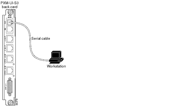
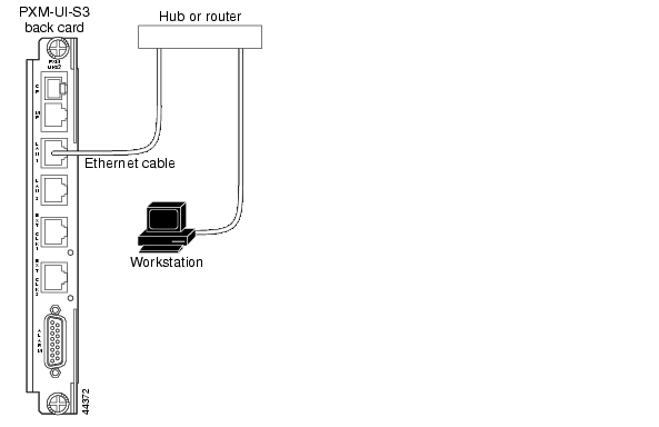
After you assemble a new switch, as described in the Cisco MGX 8850 (PXM1E/PXM45), Cisco MGX 8950, and Cisco MGX 8830 Hardware Installation Guide, you must initialize the switch before you can configure it. Although PXM cards ship with the latest version of boot firmware on the front card, the runtime firmware cannot be loaded until both front and back cards have been installed. When you initialize the switch, you are configuring the switch to load a specific runtime firmware version from the PXM hard disk.
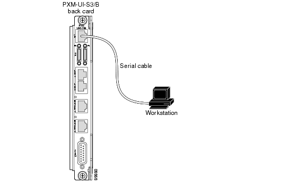
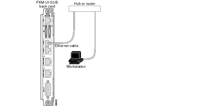
A new switch must be initialized using a console port management session. A console port management session requires a terminal or workstation with a serial connection to the Console Port (CP) port on the PXMUI-S3 back card. Figure 3-1 shows how a workstation connects to a PXM45 UI-S3 back card. Figure 3-2 shows how a workstation connects to a PXM1E UI-S3/B back card.
Note
Figure 3-1 Workstation Connection to Console Port on a PXM-UI-S3 Back Card
Figure 3-2 Workstation Connection to Console Port on a PXM-UI-S3/B Back Card
To initialize the switch, use the following procedure.
Step 1
Note
Step 2
The default switch configuration supports the following settings: 9600 bps, 8 data bits, no parity, 1 stop bit, no hardware flow control.
Step 3
Step 4
Note
Step 5
When startup is complete for an uninitialized switch, it will display the PXM backup boot prompt.
PXMbkup>Step 6
The version number is listed in the Release Notes for Cisco MGX 8850 (PXM1E/PXM45), Cisco MGX 8950, and Cisco MGX 8830, Software Version 4.0.00. You must use the same format listed in the firmware file name when you enter the number. For example, if the firmware filename is pxm1e_004.000.000.000_mgx.fw, the firmware version number you will enter is 004.000.000.000.
Step 7
PXMbkup> sysVersionSet versionReplace version with the version number for the runtime firmware. For example:
PXMbkup> sysVersionSet 002.000.001.000Step 8
PXMbkup> rebootDuring initialization, the switch will appear to boot twice. When the reboot is complete, the switch displays the Login prompt, which indicates that the firmware is loaded and the switch is ready for configuration.
Tip
Can not open file C:/version" or the message "Unable to determine size of C:/FW/filename." If this happens, press Return to display the backup boot prompt, then refer to the " Troubleshooting Upgrade Problems" section in Appendix A, "Downloading and Installing Software Upgrades."Step 9
Login: ciscopassword:unknown.7.PXM.a >
Note
Note
Note
On a Cisco MGX 8830 switch, the number 1 in the switch prompt indicates that you are managing the PXM in slot 1. If you are managing the PXM in slot 2, the switch prompt displays the number 2.The switch does not display the password during login. When login is complete, the switch prompt appears.
The switch prompt for PXM, AXSM, FRSM12, and cell bus service module (CBSM) cards uses the following format:
nodename.slot.cardtype.state>Table 3-1 describes the components in the CLI prompt.
Table 3-1 CLI Prompt Components
nodename
The nodename is the name of the node. When a new switch starts up, the node name is set to unknown. To change the name, see the " Setting and Viewing the Node Name" section which appears later in this chapter.
slot
The slot number indicates the physical slot in which the card you are configuring is installed. For most switch configuration procedures, configure the switch using the PXM cards. On Cisco MGX 8850 (PXM1E/PXM45) and Cisco MGX 8950, the PXM cards are in slots 7 and 8. In Cisco MGX 8830, the PXM cards are in slots 1 and 2.
For many line and trunk configuration procedures, you need to modify service modules (such as the CESM card), which are installed in the other slots.
cardtype
The cardtype identifies the model of the card, such as PXM or CESM.
state
The card state is active (a), standby (s), or init (i). Cards are labeled as init while they are initializing during switch startup.
Note
MGX.1.4.VHS2CT3.a >. FRSM 8T1E1 cards, however, follow the standard naming convention and display FRSM as the cardtype in the switch prompt.After initialization, the PXM in the initialized slot becomes active. If a second PXM resides in the other slot, the active PXM initiates a runtime firmware load on the other slot. After the runtime firmware loads on the nonactive PXM, the card enters standby mode, ready to take control if the active card fails.
After you log in, the switch maintains your session for the default period of 10 minutes (600 seconds) after the last keystroke is entered. If the session is idle longer than 600 seconds, the session is terminated.
Tip
Step 10
unknown.7.PXM.a > timeout <seconds>Replace seconds with the number of seconds you want the session to remain active before it times out. The maximum value is 600. To disable time-out, enter 0 seconds. The switch uses the new timeout value until you terminate the session. Each time a new session is started, the timout value returns to the default value, 600 seconds.
Once you have completed the procedure above, you have established a command line interface (CLI) management session. You can use a CLI management session to configure or monitor the switch.
Starting a CLI Management Session After Initialization
After initialization, you can terminate and start sessions at any time using the terminal or workstation connection to the CP port, which was described in the previous section.
Tip
Note
To start a CLI management session at the CP port for switch configuration and monitoring, use the following procedure.
Step 1
For instructions on preparing the terminal and the connection, refer to the previous section, " Initializing the Switch."
Step 2
Loginprompt does not appear, press Return. TheLoginprompt comes from the switch and indicates that the terminal has successfully connected to the switch.Step 3
Loginprompt appears, enter the login name supplied with your switch, then enter the password for that login name. For example:Login: superuserpassword:unknown.7.PXM.a >
Note
Note
The switch does not display the password during login. When login is complete, the switch prompt appears.
The switch prompt for PXM, AXSM, FRSM12, and CBSM cards uses the following format:
nodename.slot.cardtype.state>
Table 3-1 describes the components in the switch prompt.
Note
After you log in, the switch maintains your session for 10 minutes (600 seconds) after the last keystroke is entered. If the session is idle longer than 600 seconds, the session is terminated.
Tip
Step 4
unknown.7.PXM.a > timeout <seconds>Replace seconds with the number of seconds you want the session to remain active before it times out. The maximum value is 600. To disable timeout, enter 0 seconds. The switch uses the new timeout value until you terminate the session. Each time a new session is started, the timeout value returns to the default value, 600 seconds.
Once you have completed the procedure above, you have established a CLI management session. You can use a CLI management session to configure or monitor the switch.
Ending a CLI Management Session
CLI management sessions automatically terminate after the configured idle time. The default idle time is 600 seconds (10 minutes) and can be changed with the timeout command. To manually end a CLI management session, enter the bye or exit command.
Note
To restart the session after entering the bye or exit command, press Return, and the switch will prompt you for a username and password.
Entering Commands at the Switch Prompt
The commands in the switch operating system are associated with the cards that are installed in the switch. Before you execute a command, you must select a card that supports the command. The switch displays the currently selected card in the switch prompt. For example, the following switch prompt shows that the PXM card in slot 7 is selected:
mgx8850a.7.PXM.a>To select another card in the switch, enter the cc command:
mgx8850a.7.PXM.a> cc <slotnumber>Replace slotnumber with the slot number of the card you want to manage. You can use the dspcds command to list which slot numbers are occupied. Table 3-9 lists the valid slot numbers for each card type.
After you execute the cc command to change cards, verify that you are managing the correct card by viewing the slot number that is shown in the switch prompt. The following example shows the prompt for a CESM card in slot 6 of a Cisco MGX 8850 switch:
mgx8850a.6.CESM.a >If you have trouble entering a command, look at the switch prompt to see if you have selected the correct card and type for the command. The following example shows the response to an unrecognized command:
mgx8850a.6.CESM.a > dspdateUnknown Command: dspdateThe dspdate command runs on a PXM card. It is not recognized by a CESM card.
Tip
The default switch configuration allows you to enter command abbreviations. Because the help command is the only command that begins with he, you can use the abbreviated he command to display help. The following example demonstrates that the switch recognizes your partial entry of the help command because it proceeds to list commands.
mgx8850a.7.PXM.a> heAvailable commands------------------addprefaddprfxaddredaddrscprtnaddsctaddserialifaddslaveaddsntprmtsvraddtrapmgradduseraesa_pingarpAddarpDeletearpFlusharpShowbootChangeburnbootbyeccType <CR> to continue, Q<CR> to stop:
Tip
Notice the last line of the help command display. Because the help display is too long to appear on one screen, it is displayed in pages. Press Return to display the next page, or type q and press Return to cancel the help display.
The following example demonstrates what can appear when a command is entered at the wrong card prompt.
mgx8850a.5.FRSM.a > dspcdsUnknown Command : dspcdsIn the example above, the dspcds command is entered at the FRSM prompt, but this command is not supported on the FRSM card. The dspcds command is only supported on the PXM.
The following example demonstrates what can appear when only part of a command is entered at a service module prompt:
Ferrari.1.5.VHS2CT3.s > dspcUnknown Command : dspcThe possibilities are :dspcd dspcderrs dspchandspchancnt dspchanmap dspchansdspchanstdabr dspchstats dspcondspconsIn the example above, dspc is entered at the FRSM-2CT3 card prompt. Because there are several possible commands that start with dspc, the switch lists all supported commands that start with those letters.
The following example demonstrates what can happen if you enter only part of a command at the PXM card prompt, but only one command that starts with the letters you entered: the switch defaults to that command.
mgx8850a.7.PXM.a> clidbValue of cliDbxLevel is currently 0In the example above, clidb is entered at the PXM card prompt. Because the only command that begins with the letters clidb is clidbxlevel, the switch defaults to that command.
Note
Unknown Command :Whenever the switch displays an error message, be sure to check the spelling of the command, the parameters entered with the command, and the prompt at which the command was entered.
Getting Command Help
The following sections describe how to display the following types of command help:
•
•
•
Displaying Command Lists
The commands you can use to manage the switch are determined by your user name, which is configured for a particular access level. User names and access levels are described in more detail in the " Configuring User Access" section later in this chapter. To display a list of all the commands available to the username you used at log in, enter the help command as follows:
mgx8850a.7.PXM.a> helpTo display a list of commands that include a common set of characters, enter a question mark and the common set of characters, as shown in the following example:
mgx8850a.7.PXM.a> ? ipAvailable commands------------------cliPlugincliPlugoutcnfifipcnfilmiprotocnftrapipdelifipdspifipdspipconntaskdspipifdspipifcachedsptrapipdspvsipartdspvsipartsipifconfigpntracevsipktsetipconndebugDisplaying Detailed Command Lists
Detailed command lists display the following additional information for each command:
•
•
•
Note
To enable detailed command lists, enter the clidbxlevel command as shown in the following example:
mgx8850a.7.PXM.a> clidbxlevel 1Value of cliDbxLevel is now 1After you enter this command, you can display detailed command lists by entering the help command as shown in the following example:
mgx8850a.7.PXM.a> ?Command Access Card Log---------------------------------------------------? ANYUSER A|S|I -abortallsaves GROUP1 A +abortofflinediag SERVICE_GP A|S -abortrev SERVICE_GP A|S +actaudit SUPER_GP A +addaddr GROUP1 A +addapsln GROUP1 A +addcon GROUP1 A +addcontroller SUPER_GP A +addfltset GROUP1 A +addlink ANYUSER A -addlnloop GROUP1 A +addlpback GROUP1 A -addmaster GROUP1 A +addpart GROUP1 A +addpnni-node SUPER_GP A +addpnni-summary-addr SUPER_GP A +addpnport GROUP1 A +addport GROUP1 A +Type <CR> to continue, Q<CR> to stop:
Note
The Access column shows the access level required to enter the command. Access levels are described in the " Configuring User Access" section later in this chapter.
The Card State column identifies the card states during which the command can be executed. Valid card states are active, standby, and init. Cards are labeled as init during switch startup. The options that appear in the Card State column are described in Table 3-2.
If a plus symbol appears in the Log column, each successful execution of the command is logged. If a minus symbol appears in the column, the command is not logged.
Displaying Command Syntax and Parameters
To display the syntax of a command, enter the command without any parameters. The following example shows the syntax report provided by the switch when the addport command is entered without any parameters.
mgx8850a.7.PXM.a> addportErr: Mandatory argument required.Syntax: addport "<ifNum> <bay.line> <guaranteedRate> <maxRate> <sctID> <ifType>[-vpi <vpi>] [-minvpi <minvpi>] [-maxvpi <maxvpi>]"if -- number between 1 and 32ln -- format bay.linemin -- rates in cells/sec :max -- for OC12:between 50 and 1412830for OC3:between 50 and 353207for T3:between 50 and 96000(PLCP),104268(ADM)for E3:between 50 and 80000for T1:between 50 and 3622for E1:between 50 and 4528sct -- SCT file ID between 0 and 255, for default file use 0type -- 1: uni 2: nni 3: vnni 4: vuni 5: evuni 6: evnnivpi -- vpi between 1 and 255 for VUNI,1 and 4095 for VNNIminvpi -- minimum vpi between 0 and 255 for EVUNI,0 and 4095 for EVNNImaxvpi -- maximum vpi between 0 and 255 for EVUNI,0 and 4095 for EVNNIWhen a parameter is shown between less-than (<) and greater-than (>) symbols, the parameter represents a variable that must be replaced by a value. The values are described below the command syntax.
When the parameter is shown between brackets ([]), it is an optional parameter. If you omit an optional parameter, most commands will use the last value defined for the option. If no value has been assigned to an option, the default value is used.
Note
Tip
dspcd jim
mgx8850a.7.PXM.a>
ERR: Invalid Slot number specified
ERR: Syntax: dspcd ["slot_number"]
slot number -- optional;
Configuring User Access
The usernames and passwords supplied with your switch provide access to all switch features, and they allow you to add and delete users and change user passwords.
When configuring user access for the switch, consider the following recommendations:
•
•
•
•
The following sections describe how to add users, change passwords for existing users, delete users, and recover the user cisco password.
Adding Users
The Cisco MGX switches support up to 50 users. To create a user account, specify the following information:
•
•
•
The user name and password identify the user and determine the user access level for switch management.
An access level must be assigned to a user when the user is added to the switch. The access levels listed in Table 3-3 are used throughout this guide to indicate the level of access required to execute a command or complete a procedure. These access levels are also called access privileges. If a user has access privileges at a lower level than a command requires, the user cannot execute the command. If the user has access privileges at the level required or at a higher level, the user can execute the command.
1. SPVC = soft permanent virtual connection
2. SPVP = soft permanent virtual path
Note
To add a user to the switch, use the following procedure.
Step 1
Step 2
mgx8850a.7.PXM.a> adduser <username> <accessLevel>Enter the username using 1 to 12 alphanumeric characters. Specify the access level by entering one of the levels defined in Table 3-3.
Note
If you enter the command correctly, the switch prompts you for a password.
Step 3
Step 4
This completes the addition of the new user.
Step 5
Tip
Step 6
Tip
Changing Your Own User Password
To change your own password with the cnfpasswd command, use the following procedure.
Note
Step 1
Step 2
mgx8850a.7.PXM.a>cnfpasswdStep 3
Step 4
Step 5
This completes the change of password.
Step 6
Changing User Access Levels and Passwords with cnfuser
After you create a user, you can change that user's access level or password using the cnfuser command.
Note
To change the user level or password of a switch user, use the following procedure.
Step 1
Step 2
mgx8850a.7.PXM.a> cnfuser -u <username> [-p <password>] [-l <accessLevel>]Replace username with the name of the user for whom you are making the change.
If you are changing the password, specify the -p option and enter a password containing from 5 to 15 characters. If you are changing the user access level, specify the -l (lowercase L) option and enter the appropriate access level as shown in Table 3-3.
Note
Step 3
Step 4
The dspusers command displays all the usernames and the access level for each user as shown in the following example:
mgx8850a.7.PXM.a> dspusersUserId AccessLevel-------------------------cisco CISCO_GPservice SERVICE_GPsuperuser SUPER_GPjbowman GROUP1Deleting Users
To delete a user, use the following procedure.
Step 1
Step 2
mgx8850a.7.PXM.a> deluser <username>Enter the username using from 1 to 12 alphanumeric characters.
This completes the deletion of a user.
Step 3
Resetting the User cisco Password
If you lose or forget your password for switch access, you should ask a user with a higher access level to reset your password using the cnfuser command. If you do not have any passwords for any access levels, you can use the following password recovery procedure to reset the password for user cisco. This procedure resets the user cisco password to cisco and leaves all other passwords unchanged. (You can change the other passwords with the cnfuser command after logging in as user cisco.)
Note
Use the following procedure to reset the user cisco password.
Step 1
Caution
Step 2
Step 3
Step 4
Enabling and Disabling the User cisco Password Reset
If the switch you are managing is in an insecure area, you might want to disable the user cisco password reset feature. Otherwise, anyone with physical access to the switch CP can reset the password, deny access to other users, and reconfigure the switch. This feature can be enabled again at a later date if you know the user name and password for a user at the SERVICE_GP privilege level or higher.
To enable or disable the password reset feature, use the following procedure.
Step 1
Step 2
Step 3
Step 4
Setting and Viewing the Node Name
The switch name identifies the switch you are working on, which is important when you are managing multiple switches. The current switch name appears in the CLI prompt when you are managing PXM cards and service modules. To change the switch name, use the following procedure.
Step 1
Step 2
unknown.7.PXM.a > cnfname <node name>Enter up to 32 characters for the new node name, and since the node name is case-sensitive, be sure to use the correct case. For example:
unknown.7.PXM.a > cnfname mgx8850aThis node name will be changed to mgx8850a. Please Confirmcnfname: Do you want to proceed (Yes/No)? ycnfname: Configured this node name to mgx8850a Successfully.mgx8850a.7.PXM.a>
Note
The new name appears immediately in the next CLI prompt.
Viewing and Setting the Switch Date and Time
The switch date and time is appended to event messages and logs. To assure that events are properly time stamped, use the following procedure to view and change the date and time.
Note
Step 1
Step 2
mgx8850a.7.PXM.a> dspdateStep 3
mgx8850a.7.PXM.a> cnfdate <mm/dd/yyyy>Step 4
mgx8850a.7.PXM.a> cnftmzn <timezone>Replace timezone with one of the parameter values listed in Table 3-4. If your switch is located outside the Western Hemisphere, select GMT and use the next step to specify an offset from GMT. If your switch is located in the Western Hemisphere choose the appropriate option from Table 3-4. Daylight times are adjusted by one hour in the Fall and Spring for daylight savings. Standard times are not adjusted.
Step 5
mgx8850a.7.PXM.a> cnftmzngmt <timeoffsetGMT>Replace <timeoffsetGMT> with the offset in hours from GMT. Enter a number from -12 to +12.
Step 6
mgx8850a.7.PXM.a> cnftime <hh:mm:ss>Replace <hh> with the hour of the day (0 to 23), mm with the minute of the hour (0 to 59), and ss with the number of seconds in the minute (0 to 59).
Step 7
Configuring PNNI Node Parameters
The MGX switches support many PNNI configuration commands. This section describes how to configure the basic PNNI configuration parameters for the switch. Chapter 12, "Managing PNNI Nodes and PNNI Routing," describes how to manage PNNI after you have brought up the PNNI node.
Caution
Adding the PNNI Controller
The PNNI controller simplifies switch configuration by using PNNI protocol to discover call routes in an ATM network. Without the PNNI controller, each route through the network would have to be defined manually. Chapter 12, "Managing PNNI Nodes and PNNI Routing," provides more information on PNNI. This section describes how to enable and configure the PNNI controller for the switch.
Note
To enable and configure the PNNI controller, enter the following command:
mgx8850a.7.PXM.a> addcontroller <cntrlrId> i <cntrlrType> <slot> [cntrlrName]Table 3-5 describes the parameters for the addcontroller command.
Tip
To display the PNNI controller configuration, enter the dspcontrollers command:
mgx8850a.7.PXM.a> dspcontrollerspxm1e System Rev: 03.00 May. 07, 2002 16:42:18 GMTMGX8850 Node Alarm: MAJORNumber of Controllers: 1Controller Name:Controller Id: 2Controller Location: InternalController Type: PNNIController Logical Slot: 7Controller Bay Number: 0Controller Line Number: 0Controller VPI: 0Controller VCI: 0Controller In Alarm: NOController Error:Setting the PNNI Level and Peer Group ID
The PNNI Network Planning Guide for MGX and SES Products provides guidelines for selecting a PNNI level and peer group ID. To set these parameters in the switch, use the following procedure.
Step 1
Step 2
mgx8850a.7.PXM.a> cnfpnni-node <node-index> -enable falseThe node-index uniquely defines a logical PNNI node within the switch. Initially, there is just one logical PNNI node at the lowest PNNI level, and its index number is 1. If you add a higher level logical node to the physical node, the first higher level will be numbered two, and the next higher level will be number three. Additional levels receive sequentially higher node index numbers.
During this general node configuration, you are setting the PNNI level and peer group ID for the lowest PNNI level, so replace node-index with 1.
Note
Step 3
mgx8850a.7.PXM.a> cnfpnni-node <node-index> [-pgId level:peerGroupID]To configure the lowest PNNI level, replace <node-index> with 1. Replace level with the PNNI level you want to use, and replace peerGroupID with the 13-byte peer group ID you want to use. For example:
mgx8850a.7.PXM.a> cnfpnni-node 1 -pgId 56:47.00.9181.0000.0100.0000.0000.00Step 4
mgx8850a.7.PXM.a> cnfpnni-node <node-index> -enable trueReplace node-index with the value you used when disabling and reconfiguring the PNNI node.
Step 5
mgx8850a.7.PXM.a> dsppnni-nodeThe switch displays a report similar to the following example:
mgx8850a.7.PXM.a> dsppnni-nodenode index: 1 node name: mgx8850aLevel............... 56 Lowest.............. trueRestricted transit.. off Complex node........ offBranching restricted onAdmin status........ up Operational status.. upNon-transit for PGL election.. offNode id...............56:160:47.00918100000000001a531c2a.00001a531c2a.01ATM address...........47.00918100000000001a531c2a.00001a531c2a.01Peer group id.........56:47.00.9181.0000.0100.0000.0000.00Setting the PNNI Node Address
The PNNI Network Planning Guide for MGX and SES Products provides guidelines for setting the PNNI node address, which is identical to the switch ATM address. To set the PNNI node address, use the following procedure.
Caution
Step 1
Step 2
mgx8850a.7.PXM.a> cnfpnni-node <node-index> -enable falseThe node-index uniquely defines a logical PNNI node within the switch. Initially, there is just one logical PNNI node at the lowest PNNI level, and its index number is 1. If you add a higher level logical node to the physical node, the first higher level will be numbered two, and the next higher level will be number three. The node index is a reference to particular logical PNNI process in the node.
The PNNI address is configured at the lowest PNNI level, so replace <node-index> with 1.
Note
Step 3
mgx8850a.7.PXM.a> cnfpnni-node <node-index> [-atmAddr atm-address]To modify the PNNI address at the lowest level, replace <node-index> with 1, and replace atm-address with the 20-byte ATM address you want to use. For example:
mgx8850a.7.PXM.a> cnfpnni-node 1 -atmAddr 47.00918100000100001a531c2a.00001a531c2a.01
Note
Tip
Step 4
mgx8850a.7.PXM.a> cnfpnni-node <node-index> -enable trueReplace <node-index> with the value you used when disabling and reconfiguring the PNNI node.
Step 5
mgx8850a.7.PXM.a> dsppnni-nodeThe switch displays a report similar to the following example:
mgx8850a.7.PXM.a> dsppnni-nodenode index: 1 node name: 8850_LALevel............... 56 Lowest.............. trueRestricted transit.. off Complex node........ offBranching restricted onAdmin status........ up Operational status.. upNon-transit for PGL election.. offNode id...............56:160:47.00918100000000001a531c2a.00001a531c2a.01ATM address...........47.00918100000100001a531c2a.00001a531c2a.01Peer group id.........56:47.00.9181.0000.0100.0000.0000.00Setting the PNNI Node ID
The PNNI node ID appears in many CLI displays, including the dsppnni-node command display. The default node ID is PNNIlevel:160:defaultATMaddress. If you change the PNNI level or the node ATM address, you should also change the node ID so that the node ID represents the correct PNNI level and ATM address. This will make it easier to identify the node when using CLI commands because most CLI commands reference the node ID, not the node ATM address. For example:
mgx8850a.7.PXM.a> dsppnni-linknode index : 1Local port id: 16848897 Remote port id: 16848897Local Phy Port Id: 1:2.1:1Type. lowestLevelHorizontalLink Hello state....... twoWayInsideDerive agg........... 0 Intf index........... 16848897SVC RCC index........ 0 Hello pkt RX......... 22366Hello pkt TX......... 22178Remote node name.......8850_SFRemote node id.........56:160:47.00918100000100036b5e31b3.00036b5e31b3.01Upnode id..............0:0:00.000000000000000000000000.000000000000.00Upnode ATM addr........00.000000000000000000000000.000000000000.00Common peer group id...00:00.00.0000.0000.0000.0000.0000.00In the example above, there is no reference to the ATM address for the remote switch named 8850_SF. However, if the node ID is set to match the ATM address, it will be easy to determine the ATM address of a remote switch.
To set the PNNI node ID, use the following procedure.
Step 1
Step 2
mgx8850a.7.PXM.a> cnfpnni-node <node-index> -enable falseThe node-index uniquely defines a logical PNNI node within the switch. Initially, there is just one logical PNNI node at the lowest PNNI level, and its index number is 1. If you add a higher level logical node to the physical node, the first higher level will be numbered two, and the next higher level will be number three. The node index is a reference to particular logical PNNI process in the node.
The PNNI node ID is configured at the lowest PNNI level, so replace <node-index> with 1.
Note
Step 3
mgx8850a.7.PXM.a> cnfpnni-node <node-index> [-nodeId PNNIlevel:160:atm-address]To configure the lowest PNNI level, replace <node-index> with 1. Replace PNNIlevel with the lowest PNNI level, and replace atm-address with the 20-byte ATM address you want to use. For example:
mgx8850a.7.PXM.a> cnfpnni-node 1 -nodeId
56:160:47.00918100000100001a531c2a.00001a531c2a.01
Step 4
mgx8850a.7.PXM.a> cnfpnni-node <node-index> -enable trueReplace <node-index> with the value you used when disabling and reconfiguring the PNNI node.
Step 5
mgx8850a.7.PXM.a> dsppnni-nodeThe switch displays a report similar to the following example:
mgx8850a.7.PXM.a> dsppnni-nodenode index: 1 node name: 8850_LALevel............... 56 Lowest.............. trueRestricted transit.. off Complex node........ offBranching restricted onAdmin status........ up Operational status.. upNon-transit for PGL election.. offNode id...............56:160:47.00918100000100001a531c2a.00001a531c2a.01ATM address...........47.00918100000100001a531c2a.00001a531c2a.01Peer group id.........56:47.00.9181.0000.0100.0000.0000.00Setting and Viewing the SPVC Prefix
The PNNI Network Planning Guide for MGX and SES Products provides guidelines for selecting the SPVC prefix. The SPVC prefix is the ATM prefix that PNNI advertises for all SPVCs and Soft Permanent Virtual Paths (SPVP) on this node. The ATM address for each SPVC and SPVP is the combination of the SPVC prefix and a port identification number.
You can configure one SPVC node prefix per node. To set the SPVC prefix, use the following procedure.
Note
Note
Step 1
Step 2
mgx8850a.7.PXM.a> dspspvcprfxThe switch response is similar to the following example:
mgx8850a.7.PXM.a> dspspvcprfxSPVC Node Prefix: 47.00918100000000001a531c2a
Tip
Step 3
mgx8850a.7.PXM.a> cnfspvcprfx -prfx <prefix>Replace prefix with the 13-byte prefix you want to use. For example:
mgx8850a.7.PXM.a> cnfspvcprfx -prfx 47.00918100000100001a531c2a
Note
Note
Step 4
Displaying PNNI Summary Addresses
After you configure the PNNI level, peer group ID, ATM address, and SPVC prefix, review the summary addresses the node will advertise. If all PNNI parameters are properly coordinated, the node should display a single summary address that represents all PNNI destinations in that node. To display the summary addresses, enter the dsppnni-summary-addr command as shown in the following example:
mgx8850a.7.PXM.a> dsppnni-summary-addrnode index: 1Type.............. internal Suppress.............. falseState............. advertisingSummary address........47.0091.8100.0001.0000.1a53.1c2a/104The example above is coordinated with the examples in the previous sections, so just one PNNI summary address is broadcast to the peer group. The following example demonstrates what happens when the node ATM address and the SPVC prefix are not coordinated:
mgx8850a.7.PXM.a> dsppnni-summary-addrnode index: 1Type.............. internal Suppress.............. falseState............. advertisingSummary address........47.0091.8100.0000.0000.1a53.1c2a/104mgx8850a.7.PXM.a> dsppnni-nodenode index: 1 node name: 8850_LALevel............... 56 Lowest.............. trueRestricted transit.. off Complex node........ offBranching restricted onAdmin status........ up Operational status.. upNon-transit for PGL election.. offNode id...............56:160:47.00918100000000001a531c2a.00001a531c2a.01ATM address...........47.00918100000000001a531c2a.00001a531c2a.01Peer group id.........56:47.00.9181.0000.0100.0000.0000.00mgx8850a.7.PXM.a> dspspvcprfxSPVC Node Prefix: 47.00918100000100001a531c2aIn the example above, the node ATM address does not conform to the peer group ID or the SPVC prefix, so it must be advertised in addition to the SPVC prefix.
Configuring the MPLS Controller
The MPLS controller manages MPLS communications through the switch. Typically, the MPLS controller is used with a PNNI controller. Both MPLS and PNNI controllers can be used on the same line.
Note
Note
To enable and configure the MPLS controller, enter the following command:
mgx8850a.7.PXM.a > addcontroller <cntrlrId> i <cntrlrType> <lslot> [cntrlrName]Table 3-5 describes the parameters for the addcontroller command.
Tip
To display the MPLS controller configuration, enter the dspcontrollers command:
mgx8850a.7.PXM.a > dspcontrollersConfiguring Clock Sources
The " Guidelines for Creating a Network Clock Source Plan" section in "Preparing for Configuration," introduces two clock source configuration options:
•
•
Note
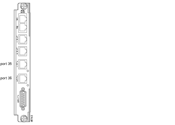
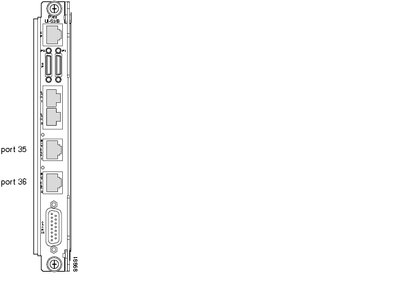
Both clock source options can use built-in hardware ports designed for Building Integrated Timing System (BITS) clock sources. Figure 3-3 shows how BITS clock sources connect to the PXM45 UI-S3 back card. Figure 3-4 shows how BITS clock sources connect to the PXM1E UI-S3/B back card.
The clock source ports on the PXM-UI-S3 and PXM-UI-S3/B cards can be used to receive clock signals from either T1 or E1 lines; the card does not support both line types simultaneously. These clock ports support stratum levels 1 to 3.
Figure 3-3 BITS Clock Source Ports on PXM45 UI-S3 Back Card
Figure 3-4 BITS Clock Source Ports on PXM1E UI-S3/B Back Card
Note
Manually Configuring BITS Clock Sources
The following procedure describes how to configure the switch to use clock sources on the BITS ports.
Note
Step 1
Step 2
mgx8850a.7.PXM.a > cnfclksrc <priority> [shelf.]slot.port -bits {e1|t1} [-revertive
{enable|disable}]
Table 3-6 describes the parameters for this command.
Step 3
Step 4
The dspclksrcs command is described in the " Managing Manually Configured Clocks Sources," in Chapter 13, "Switch Operating Procedures.".
Note
The following command example shows how to configure a primary E1 external clock source at the upper connector of the PXM1E-UI-S3. Note the command punctuation.
mgx8850a.7.PXM.a > cnfclksrc primary 7.35 -bits e1The next example configures a primary network clock source and enables the revertive option.
mgx8850a.7.PXM.a > cnfclksrc primary 7.36 -bits e1 -revertive enableThe last example disables the revertive function for an E1 BITS clock.
mgx8850a.7.PXM.a > cnfclksrc primary 7.36 -bits e1 -revertive disableEnabling NCDP on a Node
Use the following procedure to enable NCDP on each node in your network.
Step 1
M8850_LA.8.PXM.a > cnfncdp -distributionMode 1 -maxNetworkDiameter 30 -hello 300 -holdtime
300 -topoChangeTimer 300
Table 3-7 describes the options available for the cnfncdp command.
Step 2
M8850_LA.8.PXM.a > dspncdpDistribution Mode : ncdpNode stratum level : 3Max network diameter : 30Hello time interval : 300Holddown time interval : 300Topology change time interval : 300Root Clock Source : 255.255Root Stratum Level : 3Root Priority : 128Last clk src change time : Feb 21 2002 14:16:11Last clk src change reason : Topology ChangedOnce NCDP is enabled on your node, the best clock source and second best clock source are automatically selected and distributed to all nodes in the network that have NCDP enabled. If no previous NCDP clock configuration has been done, NCDP selects a root clock source that comes from an internal oscillator. If you want the root clock source to come from an external source, use the cnfncdpclksrc command as described in the "Configuring an NCDP Clock Source" section in Chapter 13, "Switch Operating Procedures."
Note
Caution
If you wish to change the BITS clock selected by NCDP, enter the cnfncdpclksrc command, as described in the "Configuring an NCDP Clock Source" section in Chapter 13, "Switch Operating Procedures."
Setting the LAN IP Addresses
The switch uses two types of IP addresses for Ethernet LAN access:
•
•
The following sections describe how to set these addresses. For information on how the switch uses these addresses and how to choose the addresses, see the "Guidelines for Creating an IP Address Plan" section in "Preparing for Configuration."
Note
Setting the Boot IP Address
The boot IP address is the LAN port IP address that a PXM card uses when it first starts up. If the switch cannot fully start, this IP address can be used to access the switch in boot mode. When the switch is properly configured (with different addresses set for the boot IP and LAN IP addresses), the boot IP address can also be used to access the standby PXM card directly, while the disk IP address can be used to access the active PXM.
Note
To set the boot IP address, use the bootChange command, which also allows you to define a remote boot location, a default gateway IP address, and a username and password for the remote boot location.
Step 1
Step 2
mgx8850a.1.PXM.a> bootChange'.' = clear field; '-' = go to previous field; ^D = quitboot device : lnPciIn this example, the switch is waiting for you to take action on the boot device option. Enter a period <.> to clear the current value (lnPci), enter minus <-> to go back to the previous field (although this is the first of 14 fields), or press Return to accept the current value and display the next option. The following example shows all options.
mgx8850a.7.PXM.a> bootChange'.' = clear field; '-' = go to previous field; ^D = quitboot device : lnPciprocessor number : 0host name :file name :inet on ethernet (e) : 172.29.52.6inet on backplane (b):host inet (h) : 0.0.0.0gateway inet (g) : 172.29.52.1user (u) :ftp password (pw) (blank = use rsh):flags (f) : 0x0target name (tn) : ??????????startup script (s) :other (o) :
Note
Step 3
Step 4
inet on ethernet (e) : 172.29.52.88 172.29.52.8:ffffff00The 172.29.52.88 address appeared as part of the prompt. If no address had been previously defined, no text would appear after the colon. In this example, 172.29.52.8 is the new boot IP address, and ffffff00 is the new network mask.
Step 5
Step 6
Step 7
Note
Setting the LAN or Disk IP Address
A local LAN connection extends switch management to all workstations that have connectivity to the LAN to which the switch is connected. Figure 3-5 shows the hardware required for a local LAN connection to a PXM45 UI-S3 card. Figure 3-6 shows the hardware required for a local LAN connection to a PXM1E UI-S3/B card.
Figure 3-5 Hardware Required for Local LAN Connections to PXM45 UI-S3 Back Cards
Note
Figure 3-6 Hardware Required for Local LAN Connections to PXM1E UI-S3/B Back Cards
Before you can manage the switch through the PXM LAN port, you must first assign an IP address to the LAN port. The LAN or disk IP address is the IP address for the Ethernet LAN port on the active PXM. The LAN IP address is also called the disk IP address because it is stored on the PXM hard disk. However, the IP address for the Maintenance Port is also stored on the hard disk and must be different, so this section refers to this address as the LAN IP address.
Tip
The LAN IP address can be set to match the boot IP address when only one IP address is available, or it can be set to a unique address to support access to the standby PXM during regular operation. For more information on how the boot and LAN IP addresses are used, see "Preparing for Configuration."
To set the IP address, enter the ipifconfig command as described in the following procedure.
Step 1
Step 2
mgx8850a.7.PXM.a> dspipif lnPci0
Note
In the IP Interface Configuration Table, look for an Internet address entry under the lnPci entry. If an IP address is configured, you can use that address and skip the rest of this procedure. However, if the address has not been entered or is incompatible with your network, you must configure a valid IP address as described in the next step.
Note
Step 3
mgx8850a.7.PXM.a> ipifconfig lnPci0 <IP_Addr> <netmask Mask>Replace <IP_Addr> with the IP address you want this port to use, and replace <Mask> with the network mask used on this network.
Note
Step 4
mgx8850a.7.PXM.a> dspipif lnPci0mgx8850a System Rev: 02.01 Sep. 17, 2001 17:39:15 PSTMGX8850 Node Alarm: NONEIP INTERFACE CONFIGURATION--------------------------------------------------------------------lnPci (unit number 0):Flags: (0x63) UP BROADCAST ARP RUNNINGInternet address: 172.29.52.88Broadcast address: 172.29.255.255Netmask 0xffff0000 Subnetmask 0xffffff00Ethernet address is 00:00:1a:53:1c:2aMetric is 0Maximum Transfer Unit size is 15001174481 packets received; 516574 packets sent502 input errors; 3 output errors3 collisionsDISK IP address: 172.29.52.88Starting a CLI Session Through the LAN Port
The switch includes a Telnet server process that you can use to connect to and manage the switch. Before you can establish a CLI Telnet session, you must set up the hardware for your access method and assign the appropriate boot and LAN IP addresses.
After the LAN IP interface has been configured and a physical path established to the Cisco MGX 8850, you can start a CLI session using a workstation with a Telnet client program. To establish a CLI management session, use the following procedure.
Step 1
C:>telnet ipaddressReplace ipaddress with the appropriate LAN IP address as follows:
•
•
•
Note
Step 2
The Login prompt comes from the switch and indicates that the workstation has connected successfully to the switch.
Step 3
Step 4
After you successfully log in, a prompt appears that is similar to the following:
mgx8850a.7.PXM.a>
Configuring for Network Management
The Cisco MGX switches include a Simple Network Management Protocol (SNMP) agent that you can configure for communications with a network management station such as Cisco WAN Manager (CWM) or a third-party SNMP manager. When configured for SNMP management, the switch accepts configuration commands from management stations and sends status and error messages to the management station.
Typically, CWM operates on a workstation that is connected to an IP network, and CWM uses IP over ATM connections to connect to Cisco MGX switches. For information on establishing this type of access, see the " Configuring the Switch" section in "Supporting and Using Additional CLI Access Options."
To support the auto-discovery feature of CWM, ILMI should be brought up on all links between the CWM workstation and the switches it will manage. For information on bringing up ILMI on a PXM1E card, see the " Configuring ILMI on a Port" section in Chapter 11, "Provisioning PXM1E Communication Links." For information on bringing up ILMI on an AXSM card, refer to the "Configuring ILMI on a Port" section in Chapter 2 of the Cisco ATM Services (AXSM) Software Configuration Guide and Command Reference for MGX Switches.
The following tasks are described in this section:
•
•
•
Configuring the SNMP Trap Source IP Address
The SNMP trap source IP address is sent to SNMP managers, such as CWM, in the SNMP trap Packet Data Unit (PDU). This IP address identifies the source of the trap and can be used by the SNMP manager to access the remote SNMP agent. This address must be configured to enable communications with an SNMP manager.
Note
The switch can communicate with an SNMP manager over the LAN or ATM IP interfaces. In some installations, the LAN IP interface will be used for CLI management and the ATM IP interface will be used for SNMP management. When you select the SNMP trap manager IP address, you must select the correct interface address.
To define the SNMP trap manager IP address, enter the cnftrapip command as follows:
mgx8850a.7.PXM.a> cnftrapip <ipaddress>The IP address should match the LAN IP address or the ATM interface IP address. For information on setting and viewing the LAN IP address, see the " Setting the LAN IP Addresses" section earlier in this chapter. For information on setting and viewing the ATM interface IP address, see the " Configuring the Switch" section in "Supporting and Using Additional CLI Access Options."
Configuring the SNMP Manager Destination IP Address
The SNMP Manager destination IP address identifies the IP address of an SNMP manager, such as CWM, to which the switch sends SNMP traps. If you are using CWM to manage the switch, CWM will automatically configure the destination IP address on the switch. If you are using another SNMP manager, you can configure the destination IP address with the addtrapmgr command as follows:
mgx8850a.7.PXM.a> addtrapmgr <ipaddress> <port>Replace ipaddress with the IP address of the SNMP manager, and replace port with the UDP port number assigned to that manager. For more information on the SNMP manager IP address, refer to the SNMP manager documentation.
Configuring the Community String and General Switch Information
To configure information about a switch in the local SNMP agent, use the following procedure.
Step 1
Step 2
mgx8850a.7.PXM.a> cnfsnmp community [password]If the password parameter is not specified, the password becomes <private>.
Step 3
mgx8850a.7.PXM.a> cnfsnmp location [location]If the location parameter is not specified, the location is set to null (no text). The location value is sent to SNMP managers when information is requested about the sysLocation MIB object.
Step 4
mgx8850a.7.PXM.a> cnfsnmp contact [contact]If the contact parameter is not specified, the location is set to null (no text). The contact value is sent to SNMP managers when information is requested about the sysContact MIB object.
Step 5
mgx8850a.7.PXM.a> dspsnmppop20two System Rev: 02.01 Dec. 28, 2000 20:37:18 PSTMGX8850 Node Alarm: NONECommunity: privateSystem Location: Pubs LabSystem Contact Jim
Verifying the Hardware Configuration
Before you can configure your switch, you need to collect information about the cards and software installed on the switch. The primary reason for collecting this information is to verify that the correct cards are installed in the correct slots, and that the back cards installed are indeed compatible with the front cards they serve. The " Hardware Survey Worksheets" section of "Hardware Survey and Software Configuration Worksheets," provides worksheets that you can use to record the hardware installation for the different Cisco MGX switches.
The following procedure describes how to display the information you need to complete the hardware survey worksheets. It also describes how to verify that the correct upper and lower back cards are installed for each front card.
Step 1
Step 2
mgx8850a.7.PXM.a> dspcdsA Cisco MGX 8830 switch displays a report similar to the following example:
mgx8830b.1.PXM.a> dspcdsmgx8830b System Rev: 03.00 Apr. 25, 2002 23:20:16 GMTChassis Serial No: SCA053000KM Chassis Rev: A0 GMT Offset: 0Node Alarm: MAJORCard Front/Back Card Alarm Redundant RedundancySlot Card State Type Status Slot Type--- ---------- -------- -------- ------- -----01 Active/Active PXM1E-4-155 MAJOR 02 PRIMARY SLOT02 Standby/Active PXM1E-4-155 NONE 01 SECONDARY SLOT03 Active/Empty RPM NONE NA NO REDUNDANCY04 Active/Active FRSM_2CT3 MINOR 05 PRIMARY SLOT05 Standby/Active FRSM_2CT3 NONE 04 SECONDARY SLOT06 Active/Active CESM_8T1 NONE NA NO REDUNDANCY07 Active/Active SRM_3T3 NONE 14 PRIMARY SLOT11 Active/Active FRSM_8T1 NONE NA NO REDUNDANCY12 Empty --- --- --- ---13 Standby/Active FRSM_8T1 NONE NA NO REDUNDANCY14 Standby/Active SRM_3T3 NONE 07 SECONDARY SLOTA Cisco MGX 8850 switch displays a report similar to the following example:
M8850_LA.8.PXM.a > dspcdsM8850_LA System Rev: 04.00 May. 08, 2003 08:23:19 GMTChassis Serial No: SAA03230375 Chassis Rev: B0 GMT Offset: 0Node Alarm: CRITICALCard Front/Back Card Alarm Redundant RedundancySlot Card State Type Status Slot Type--- ---------- -------- -------- ------- -----01 Active/Active AXSM_4OC12 NONE NA NO REDUNDANCY02 Active/Active AXSM_4OC12 NONE NA NO REDUNDANCY03 Active/Active AXSM_16T3E3 NONE NA NO REDUNDANCY04 Active-F/Active AXSME_16T3E3 MAJOR NA NO REDUNDANCY05 Active-F/Active AXSME_2OC12 MAJOR NA NO REDUNDANCY06 Active/Active AXSM_16OC3_B MAJOR NA NO REDUNDANCY07 Empty Resvd/Empty --- MAJOR 08 PRIMARY SLOT08 Active/Active PXM45B NONE 07 SECONDARY SLOT09 Active/Active RPM_PR NONE NA NO REDUNDANCY10 Empty --- --- --- ---11 Mismatch/Empty UNKNOWN NONE NA NO REDUNDANCY12 Active/Active AXSM-32-T1E1-E NONE NA NO REDUNDANCY13 Active/Active FRSM_2CT3 NONE NA NO REDUNDANCY14 Active/Active FRSM_8T1 NONE NA NO REDUNDANCY15 Empty --- --- --- ---Type <CR> to continue, Q<CR> to stop:M8850_LA System Rev: 04.00 May. 08, 2003 08:23:19 GMTChassis Serial No: SAA03230375 Chassis Rev: B0 GMT Offset: 0Node Alarm: CRITICALCard Front/Back Card Alarm Redundant RedundancySlot Card State Type Status Slot Type--- ---------- -------- -------- ------- -----16 Active/Active SRME_OC3 NONE 15 SECONDARY SLOT29 Active/Active CESM_8T1 NONE NA NO REDUNDANCY30 Active/Active FRSM_HS2/B NONE NA NO REDUNDANCY31 Empty --- --- --- ---32 Empty --- --- --- ---A Cisco MGX 8950 switch displays a report similar to the following example:
M8950_DC.8.PXM.a > dspcdsM8950_DC System Rev: 04.00 May. 08, 2003 09:10:06 GMTChassis Serial No: SCA0504043H Chassis Rev: A0 GMT Offset: 0Node Alarm: CRITICALCard Front/Back Card Alarm Redundant RedundancySlot Card State Type Status Slot Type--- ---------- -------- -------- ------- -----01 Active/Active AXSM_4OC12 MINOR NA NO REDUNDANCY02 Active/Active AXSM_16OC3 NONE NA NO REDUNDANCY03 Empty --- --- --- ---04 Empty --- --- --- ---05 Active/Active AXSM_1OC48_B NONE NA NO REDUNDANCY06 Empty --- --- --- ---07 Standby/Active PXM45B NONE 08 PRIMARY SLOT08 Active/Active PXM45C NONE 07 SECONDARY SLOT09 Active/Empty XM_60 NONE NA NO REDUNDANCY10 Active/Empty XM_60 NONE NA NO REDUNDANCY11 Active/Empty RPM NONE NA NO REDUNDANCY12 Active/Active AXSM_16OC3 NONE NA NO REDUNDANCY13 Empty --- --- --- ---14 Active/Active AXSM_4OC12 NONE NA NO REDUNDANCY15 Active/Active AXSM-1-9953-XG MINOR NA NO REDUNDANCYType <CR> to continue, Q<CR> to stop:M8950_DC System Rev: 04.00 May. 08, 2003 09:10:06 GMTChassis Serial No: SCA0504043H Chassis Rev: A0 GMT Offset: 0Node Alarm: CRITICALCard Front/Back Card Alarm Redundant RedundancySlot Card State Type Status Slot Type--- ---------- -------- -------- ------- -----16 Active/Active AXSM-4-2488-XG NONE NA NO REDUNDANCY25 Active/Empty XM_60 NONE NA NO REDUNDANCY26 Active/Empty XM_60 NONE NA NO REDUNDANCYM8950_DC.8.PXM.a >Step 3
•
•
•
Step 4
a.
mgx8830b.1.PXM.a> dspcd <slot>The dspcd command displays information that is unique to a particular card. For PXM1E cards, the switch displays a report similar to the following example:
mgx8830b.1.PXM.a> dspcd 2mgx8830b System Rev: 03.00 Apr. 25, 2002 22:51:15 GMTMGX8830 Node Alarm: MAJORSlot Number 2 Redundant Slot: 1Front Card Upper Card Lower Card---------- ---------- ----------Inserted Card: PXM1E-4-155 UI Stratum3 SMFIR_4_OC3Reserved Card: PXM1E-4-155 UI Stratum3 SMFIR_4_OC3State: Standby Active ActiveSerial Number: S1234567890 SAK0325008J SAG05415SW9Prim SW Rev: 3.0(0.39)A --- ---Sec SW Rev: 3.0(0.39)A --- ---Cur SW Rev: 3.0(0.39)A --- ---Boot FW Rev: 3.0(0.26)A --- ---800-level Rev: E2 03 4P800-level Part#: 800-12345-01 800-05787-01 800-18663-01CLEI Code: /0 0Reset Reason: On Reset From ShellCard Alarm: NONEFailed Reason: NoneMiscellaneous Information:Type <CR> to continue, Q<CR> to stop:mgx8830b System Rev: 03.00 Apr. 25, 2002 22:51:15 GMTMGX8830 Node Alarm: MAJORCrossbar Slot Status: EMPTYAlarm Causes------------NO ALARMSmgx8850a.7.PXM.a>
Note
For CBSMs, the switch displays a report similar to the report displayed on the PXM cards. The following example shows the dspcd report for a CESM8T1 card:
mgx8830b.1.PXM.a> dspcd 6mgx8830b System Rev: 03.00 Apr. 25, 2002 23:01:03 GMTMGX8830 Node Alarm: MAJORSlot Number: 6 Redundant Slot: NONEFront Card Back Card---------- ---------Inserted Card: CESM_8T1 RJ48_8T1Reserved Card: UnReserved UnReservedState: Active ActiveSerial Number: A79907 A12475Prim SW Rev: 20.0(0.106)D ---Sec SW Rev: 20.0(0.106)D ---Cur SW Rev: 20.0(0.106)D ---Boot FW Rev: 1.0(2.0) ---800-level Rev:800-level Part#: 000-00000-00 000-00000-00CLEI Code:Reset Reason: On Reset from PXMCard Alarm: NONEFailed Reason: NoneMiscellaneous Information:Type <CR> to continue, Q<CR> to stop:mgx8830b System Rev: 03.00 Apr. 25, 2002 23:01:03 GMTMGX8830 Node Alarm: MAJORCrossbar Slot Status: No CrossbarAlarm Causes------------NO ALARMSFor SRM cards, the switch displays a report similar to the following example:
mgx8830b.1.PXM.a> dspcd 7mgx8830a System Rev: 03.00 Apr. 25, 2002 23:10:08 GMTMGX8830 Node Alarm: MAJORSlot Number 7 Redundant Slot: 14Front Card Back Card---------- ---------Inserted Card: SRM_3T3 BNC_3T3Reserved Card: UnReserved UnReservedState: Active ActiveSerial Number: 955802 SBK043600TTPrim SW Rev: --- ---Sec SW Rev: --- ---Cur SW Rev: --- ---Boot FW Rev: --- ---800-level Rev: BB A0800-level Part#: 000-00000-00 800-03148-02CLEI Code: BAI9A6VAAAReset Reason: On Power upCard Alarm: NONEFailed Reason: NoneMiscellaneous Information:Type <CR> to continue, Q<CR> to stop:mgx8830 System Rev: 03.00 Apr. 25, 2002 23:10:08 GMTMGX8830 Node Alarm: MAJORCrossbar Slot Status: No CrossbarAlarm Causes------------NO ALARMS
Note
b.
–
–
Tip
Step 5
Note
If any of the cards are installed incorrectly, refer to the Cisco MGX 8850 (PXM1E/PXM45), Cisco MGX 8950, and Cisco MGX 8830 Hardware Installation Guide for instructions on installing the cards correctly.
Table 3-9 Valid Card Installation Options
AUSM8T1/B
AUSM8E1/B8 port ATM Universal Service Modules with T1/E1 interfaces
RJ48-8T1
RJ48-8E1
R-RJ48-8T1
R-RJ48-8E1
SMB-8E1
R-SMB-8E1Upper and lower
1-6, 9-14, 17-22, 25-30
3-6, 10-13
—
—
AXSM-1-2488
1 port
OC-48/STM-64
Note
SMFSR-1-2488
SMFLR-1-2488
SMFXLR-1-2488Upper
1-6, 9-14
—
—
Yes
AXSM-1-2488/B
1 port OC-48/STM-16
Note
SMFSR-1-2488/B
SMFLR-1-2488/B
SMFXLR-1-2488/BUpper
1-6, 9-14
—
Yes
Yes
AXSM-1-9953-
XG1-port OC48/STM-16
SMFSR-1-9953
SMFIR-1-9953
SMFLR-1-9953
SMFXLR-1-9953
Upper and lower (full height back card)
—
—
1-6, 11-16
No1
AXSM-2-622-E
2-port OC-12/STM-4 (622 Mbps)
SMFIR-1-622/C
SMFLR-1-622/CUpper
1-6, 9-14
—
—
Yes
AXSM-4-622
4-port OC-12
SMFIR-2-622
SMFLR-2-622Upper and lower
1-6, 9-14
—
—
Yes
AXSM-4-622/B
4-port OC-12
SMFIR-2-622/B
SMFLR-2-622/BUpper and lower
1-6, 9-14
—
1-6, 11-16
—
AXSM-4-2488-
XGOC192/STM-16
(clear or channelized to DS3)
•
(no FRU support)The following back cards support FRUS:
•
SFP•
SFPUpper and lower (full height back card)
—
—
1-6, 11-16
No1
AXSM-8-155-E
8-port OC-3/STM-1
(155 Mbps)MMF-4-155-MT/B
SMFIR-4-155-LC/B
SMFLR-4-155-LC/B
SMB-4-155Upper
1-6, 9-14
—
—
Yes
AXSM-16-155
16-port OC-3
MMF-8-155-MT
MMF-8-155-MT/B
SMFIR-8-155-LC
SMFIR-8-155-LC/B
SMFLR-8-155-LC
SMFLR-8-155-LC/BUpper and lower
1-6, 9-14
—
—
—
AXSM-16-155/B
16-port OC-3
SMB-4-155
MMF-8-155-MT/B
SMFIR-8-155-LC/B
SMFLR-8-155-LC/BUpper and lower
1-6, 9-14
—
1-6, 11-16
—
AXSM-16-T3E3
16-port T3/E3
SMB-8-T3
SMB-8-E3Upper and lower
1-6, 9-14
—
—
—
AXSM-16-T3E3/B
16-port T3/E3
SMB-8-T3
SMB-8-E3Upper and lower
1-6, 9-14
—
1-6, 11-16
—
AXSM-16-T3E3-E
16-port T3/E3
SMB-8-T3
SMB-8-E3Upper and lower
1-6, 9-14
—
—
No
AXSM-32-E1-E
32-port E1
MCC7-16-E1
RBBN8-16-T1E1
Upper
1-6, 9-14
—
—
No
AXSM-32-T1-E
32-port T1
RBBN8-16-T1E1
Upper and lower
1-6, 9-14
—
—
No
CESM-8E1
CESM-8T1
CESM-8T1/B8 port Circuit Emulation Service Module with T1 or E1 interfaces
RJ48-8T1
RJ48-8E1
R-RJ48-8T1
R-RJ48-8E1
SMB-8E1
R-SMB-8E1Upper and lower
1-6, 9-14, 17-22, 25-30
3-6, 10-13
—
—
FRSM-12-T3E3
12-port T3/E3
SMB-6-T3E3
Upper and lower
1-6, 9-14
—
—
No
FRSM-2CT3
2 port channelized Frame Relay Service Module with T3 interfaces
RJ48-8T1
RJ48-8E1
R-RJ48-8T1
R-RJ48-8E1
SMB-8E1
R-SMB-8E1Upper and lower
1-6, 9-14, 17-22, 25-30
3-6, 10-13
—
—
FRSM-8T1
FRSM-8E18 port Frame Relay Service Modules with T1 or E1 interfaces
RJ48-8T1
RJ48-8E1
R-RJ48-8T1
R-RJ48-8E1
SMB-8E1
R-SMB-8E1Upper and lower
1-6, 9-14, 17-22, 25-30
3-6, 10-13
—
—
FRSM-8T1-C
FRSM-8E1-C8 port Frame Relay Service Module with T1 or E1 interfaces
RJ48-8T1
R-RJ48-8T1
SMB-8E1Upper and lower
1-6, 9-14, 17-22, 25-30
3-6, 10-13
—
—
FRSM-HS2/B
2 port Frame Relay Service Module with HSSI interfaces
SCS12-2HSSI/B
MGX-121N1-8SUpper and lower
1-6, 9-14, 17-22, 25-30
3-6, 10-13
—
—
PXM1E
Processor Switch Module
UI Stratum-3/B
Upper
7 and 8
1 and 2
—
—
—
PXM interface back card
Lower
Yes
PXM45
Processor Switch Module
UI Stratum-3
Upper
7 and 8
—
—
—
—
—
PXM Hard Disk Drive
Lower
—
PXM45/B
Processor Switch Module
UI Stratum-3
Upper
7 and 8
—
—
7 and 8
—
PXM Hard Disk Drive
Lower
—
PXM45/C
Processor Switch Module
UI Stratum-3/B
Upper
7 and 8
—
—
7 and 8
—
—
PXM Hard Disk Drive
Lower
—
RPM-PR-256
RPM-PR-512Route Processor Module
MGX-RJ45-4E/B
MGX-RJ45-FE
MGX-MMF-FEUpper and lower
1-6, 9-14
3-6, 10-13
—
—
RPM-XF-512
Route Processor Module
Upper Bay:
•
Lower Bay:
•
•
Note
Upper and lower
1-6, 9-14
—
1-6, 11-16
—
SRM-3T3
3 port Service Redundancy Module with T3 interfaces
BNC-3T3-M
Upper and lower
15,16, 31, 32
7 and 14
—
—
SRME
3 port Service Redundancy Module with T3 interfaces
MGX-SMFIR-1-155
MGX-STM1-EL-1Upper and lower
15,16, 31, 32
7 and 14
—
Yes
VISM-PR-8E1
8-port E1 Voice Internetworking Service Module
MGX-VISM-PR-8E1
AX-SMB-8E1
AX-R-SMB-8E1
AX-RJ48-8E1
AX-R-RJ48-8E1
MGX-R-RJ48-8E1Upper and lower
1-6, 9-14, 17-22, 25-30
3-6, 10-13
—
—
VISM-PR-8T1
8-port T1 Voice Internetworking Service Module
MGX-VISM-PR-8T1
AX-RJ48-8T1
AX-R-RJ48-8T1Upper and lower
1-6, 9-14, 17-22, 25-30
3-6, 10-13
—
—
XM60
Switch Module 60
60 Gbps switch fabricnone
none
—
—
9, 10, 25, 26
—
1 Note that APS is supported, but you do not need an APS connector because APS capabilities are built into the card.
![]()
![]()
![]()
![]()
![]()
![]()
![]()
![]()
Posted: Thu May 31 17:05:12 PDT 2007
All contents are Copyright © 1992--2007 Cisco Systems, Inc. All rights reserved.
Important Notices and Privacy Statement.