|
|

Table Of Contents
Managing PNNI Nodes and PNNI Routing
Creating Upper Level Peer Groups
Enabling and Disabling Routes Through a Node
Enabling and Disabling Point-to-Multipoint Routes
Adding an ATM Summary Address Prefix
Configuring SVCC RCC Variables
Configuring Routing Policies for Background Routing Tables
Managing PNNI Route and Link Selection
Configuring the Route Selection Method (First Fit or Best Fit)
Configuring the Best-Fit Route Selection Method
Configuring Link Selection for Parallel Links
Configuring the Maximum Bandwidth for a Link
Configuring the Administrative Weight
Configuring the Bandwidth Overbooking Factor
Improving and Managing Rerouting Performance
Displaying Node Configuration Information
Displaying the PNNI Node Table
Displaying the PNNI Summary Address
Displaying PNNI Interface Parameters
Displaying the PNNI Link Table
Displaying the PNNI Routing Policy
Displaying Routing Policy Parameters
Assigning Address Prefixes and AESAs
Displaying CUG Configuration Data
Setting a Default Address for CUG Validation
Deleting a Default CUG Address
Managing Access Between Users in the Same CUG
Managing Access Between a CUG Member and Non-Members or Members of other CUGS
Maintaining a Persistent Network Topology in CWM
Displaying the Network Topology Database
Deleting a Node from the Topology Database
Deleting a Link from the Topology Database
2
Managing PNNI Nodes and PNNI Routing
This chapter provides procedures that you can use to manage Private Network-to-Network Interface (PNNI) nodes and routes. This chapter includes the following sections:
•
Managing PNNI Route and Link Selection
•
•
Note
Managing PNNI Nodes
The following sections describe how to configure upper level peer groups and how to manage the PNNI node.
Creating Upper Level Peer Groups
Upper level peer groups enable routing from one PNNI peer group to another. If you are managing a single peer group WAN, you do not need to create upper level peer groups.
Note
After you configure the lowest level PNNI nodes, all nodes within the same peer group can communicate with each other. All you need to do to enable communications between two nodes in a peer group is to add a PNNI trunk between them as described in the " ATM Trunk Configuration Quickstart" section in Chapter 11, "Provisioning PXM1E Communication Links." To enable routing between different peer groups at the same level, you must create one or more upper level peer groups.
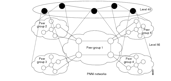
The actual procedure for creating an upper level peer group for your WAN depends on the structure of your WAN. This section shows how to create an upper level peer group for the WAN shown in Figure 12-1.
Figure 12-1 Example Hierarchical PNNI Network Topology Showing a Two-Level Hierarchy
In Figure 12-1, the five level-56 peer groups are isolated from each other until the upper level peer group is created. The members of the upper level peer group are the peer group leaders from the lower level peer groups. To create an upper level peer group, you need to configure the peer group leaders and add the upper level PNNI process to each peer group leader (PGL) node. It is also a good practice to configure secondary peer group leaders that can take over if a PGL fails.
To configure peer group leaders, use the following procedure.
Step 1
Add the upper level PNNI logical node that will participate in the higher level PNNI group using the addpnni-node <level> command.
Replace level with the PNNI level for the higher level peer group. The PNNI level value must be smaller than the level value for the lower level peer groups. The following example creates a logical PNNI node at PNNI level 48.
mgx8830a.1.PXM.a > addpnni-node 48
Note
Step 2
mgx8830a.1.PXM.a > dsppnni-electionnode index: 1PGL state...... OperNotPgl Init timeliest)....... 15Priority....... 0 Override delay(sec).. 30Re-election time(sec) 15Pref PGL...............0:0:00.000000000000000000000000.000000000000.00PGL....................0:0:00.000000000000000000000000.000000000000.00Active parent node id..0:0:00.000000000000000000000000.000000000000.00In the example above, the PGL state indicates the PGL status of each of two logical nodes, and the priority value is what is used to determine if the node will become PGL. Since a PGL represents the peer group at a higher level, logical node 1 (node index 1) is the only node that can become a PGL. In this example, both logical nodes are set to the default value 0, and this value prevents a node from becoming a peer group leader.
Step 3
mgx8830a.1.PXM.a > cnfpnni-election node-index -priority valueReplace node-index with the index that identifies the logical node you are modifying, and replace value with the new priority value. A zero value prevents the node from becoming a PGL. If only one node in a peer group has a non-zero priority, that node will become PGL. If multiple nodes have non-zero priority values, the node with the highest priority value becomes PGL. The following example shows what happens after you set the priority level and view the PGL status.
mgx8830a.1.PXM.a > cnfpnni-election 1 -priority 200mgx8830a.1.PXM.a > dsppnni-electionnode index: 1PGL state...... AwaitUnanimity Init time(sec)....... 15Priority....... 200 Override delay(sec).. 30Re-election time(sec) 15Pref PGL...............56:160:47.00918100000100036b5e31b3.00036b5e31b3.01PGL....................0:0:00.000000000000000000000000.000000000000.00Active parent node id..0:0:00.000000000000000000000000.000000000000.00node index: 2PGL state...... Starting Init time(sec)....... 15Priority....... 0 Override delay(sec).. 30Re-election time(sec) 15Pref PGL...............0:0:00.000000000000000000000000.000000000000.00PGL....................0:0:00.000000000000000000000000.000000000000.00Active parent node id..0:0:00.000000000000000000000000.000000000000.00The first time the dsppnni-election command was entered, the PGL state was OperNotPgl, which means that the node is operating, but is not operating as a PGL. After the priority is changed, the PGL state changes to AwaitUnanimity, which means the node is communicating with the other nodes in its peer group to see if it has the highest priority and should be PGL. If you enter the dsppnni-election command again after about 15 seconds, the PGL state changes as shown in the following example:
mgx8830a.1.PXM.a > dsppnni-electionnode index: 1PGL state...... OperPgl Init time(sec)....... 15Priority....... 250 Override delay(sec).. 30Re-election time(sec) 15Pref PGL...............56:160:47.00918100000100036b5e31b3.00036b5e31b3.01PGL....................56:160:47.00918100000100036b5e31b3.00036b5e31b3.01Active parent node id..48:56:47.009181000001000000000000.00036b5e31b3.00node index: 2PGL state...... OperNotPgl Init time(sec)....... 15Priority....... 0 Override delay(sec).. 30Re-election time(sec) 15Pref PGL...............0:0:00.000000000000000000000000.000000000000.00PGL....................0:0:00.000000000000000000000000.000000000000.00Active parent node id..0:0:00.000000000000000000000000.000000000000.00In the example above, the PGL state changes to show that logical node 1 is now the PGL. Notice that the priority value is 250. An earlier example in this procedure set the priority to 200. When a node is elected PGL, the node adds 50 to its priority value to prevent instability that might be caused by other peer group nodes with a marginally higher priority value.
Step 4
Enabling and Disabling Routes Through a Node
The restricted transit option allows you to allow or block call routes that pass through the node and terminate on other nodes. The default setting for this option enables calls to pass through.
To enable or disable PNNI routing through a node, enter the cnfpnni-node command as follows:
mgx8830a.1.PXM.a > cnfpnni-node <node-index > -transitRestricted on|offReplace node-index with the index that identifies the logical node you are modifying, and enter either on or off for the -transitRestricted parameter. When this parameter is set to on, the node only accepts calls that terminate on this node. When the -transitRestricted parameter is set to off, the node accepts calls that pass through the node and terminate on other nodes.
To view the status of the -transitRestricted option, enter the dsppnni-node command as shown in the following example:
mgx8830a.1.PXM.a > dsppnni-nodenode index: 1 node name: 8850_LALevel............... 56 Lowest.............. trueRestricted transit.. on Complex node........ offBranching restricted onAdmin status........ up Operational status.. upNon-transit for PGL election.. offNode id...............56:160:47.00918100000100001a531c2a.00001a531c2a.01ATM address...........47.00918100000100001a531c2a.00001a531c2a.01Peer group id.........56:47.00.9181.0000.0100.0000.0000.00Enabling and Disabling Point-to-Multipoint Routes
The branching restricted option allows you to allow or block point-to-multipoint calls. The default setting for this option enables point-to-multipoint calls.
To enable or disable point-to-multipoint routes through a node, enter the cnfpnni-node command as follows:
mgx8830a.1.PXM.a > cnfpnni-node <node-index > -branchingRestricted on|offReplace node-index with the index that identifies the logical node you are modifying, and enter either on or off for the -branchingRestricted parameter. When this parameter is set to on, the node does not accept point-to-multipoint calls. When the -branchingRestricted parameter is set to off, the node accepts point-to-multipoint calls.
To view the status of the -branchingRestricted option, enter the dsppnni-node command as shown in the following example:
mgx8830a.1.PXM.a > dsppnni-nodenode index: 1 node name: 8850_LALevel............... 56 Lowest.............. trueRestricted transit.. off Complex node........ offBranching restricted onAdmin status........ up Operational status.. upNon-transit for PGL election.. offNode id...............56:160:47.00918100000100001a531c2a.00001a531c2a.01ATM address...........47.00918100000100001a531c2a.00001a531c2a.01Peer group id.........56:47.00.9181.0000.0100.0000.0000.00Adding an ATM Summary Address Prefix
Enter the addpnni-summary-addr command to add an ATM summary address prefix for a PNNI logical node on the switch.
mgx8830a.1.PXM.a > addpnni-summary-addr <node-index> <address-prefix> <prefix-length> [-type]
[-suppress] [-state]
Table 12-1 lists the parameter descriptions for the addpnni-summary-addr command.
Configuring SVCC RCC Variables
Configure SVCC-based RCC variables with the cnfpnni-svcc-rcc-timer command as follows:
mgx8830a.1.PXM.a > cnfpnni-svcc-rcc-timer <node-index> [-initTime] [-retryTime]
[-callingIntegrityTime] [-calledIntegrityTime]
This defines a node's initial PNNI SVCC-based variables, as shown in Table 12-2.
Configuring Routing Policies for Background Routing Tables
Configure the routing policies used for background routing tables generation with the cnfpnni-routing-policy command as follows:
mgx8830a.1.PXM.a > cnfpnni-routing-policy [-sptEpsilon] [-sptHolddown] [-bnPathHolddown]
[-loadBalance] [-onDemand] [-awBgTable] [-ctdBgTable] [-cdvBgTable]
Table 12-3 lists the parameter descriptions for the cnfpnni-routing-policy command.
Configuring PNNI Timers
Configure the PNNI timers with the cnfpnni-timer command.
mgx8830a.1.PXM.a > cnfpnni-timer <node-index> <options>You can define the initial PNNI timer values and significant change thresholds of a PNNI logical node. Table 12-4 lists the parameter descriptions for the cnfpnni-timer command.
Managing PNNI Route and Link Selection
The following sections describe how to control route and link selection for the links on each PNNI node.
Configuring the Route Selection Method (First Fit or Best Fit)
When the PNNI controller searches for routes, it can choose the first route that meets the call requirements, or it can choose the route that provides the best performance. The first fit method chooses the first available route and reduces call processing time. The best fit method chooses the optimum route, but it takes longer to select the route. The default setting is first fit.
Note
To configure the route selection method, enter the cnfpnni-routing-policy command as follows:
mgx8830a.1.PXM.a > cnfpnni-routing-policy -onDemand firstfit|bestfitEnter firstfit to select the first route discovered, or enter bestfit to select the optimum route.
To display the route selection method, enter the dsppnni-routing-policy command as follows:
mgx8830a.1.PXM.a > dsppnni-routing-policySPT epsilon......... 0 Load balance........ randomSPT holddown time... 1 On demand routing... first fitSPT path holddown time 2 AW Background Table onCTD Background Table on CDV Background Table onThe parameter labeled On demand routing shows which route selection method is configured.
Configuring the Best-Fit Route Selection Method
When the PNNI controller is configured to choose the best route and it discovers multiple eligible routes, the load balancing option determines which route to select. The option settings are random and maxbw, which selects the route with the greatest available bandwidth. Random selection is used to balance the load.
Note
To configure the best-fit route selection method, use the cnfpnni-routing-policy command as follows:
mgx8830a.1.PXM.a > cnfpnni-routing-policy -loadBalance random|maxbwEnter random to balance route selection, or enter maxbw to select the route with the greatest available bandwidth.
To display the route selection method, enter the dsppnni-routing-policy command as follows:
mgx8830a.1.PXM.a > dsppnni-routing-policySPT epsilon......... 0 Load balance........ randomSPT holddown time... 1 On demand routing... first fitSPT path holddown time 2 AW Background Table onCTD Background Table on CDV Background Table onThe parameter labeled Load balance shows which best-fit route selection method is configured.
Configuring Preferred Routes
You can manually create a route that is preferred for specific SPVC and SPVP connections. Once a preferred route is created, the associated SPVC or SPVP connections will attempt to route via the preferred route before attempting other routes.
Note
Preferred routes can be configured to be directed or non-directed. A directed route only attempts a connection on the preferred route. If the connection cannot route over the preferred route, that connection will go into a failed state. A non-directed route first attempts to route over the preferred route. If the preferred route is not available, the connection will be attempted over other routes.
Keep the following in mind when planning preferred routes:
•
•
•
•
•
•
•
Note
A preferred route consists of a sequential list of up to 20 nodes, including the local node that hosts the starting point of the preferred route. The destination node can be up to 19 network elements (NEs), or 19 NNI links, away from the local node.
Note
Maintaining the Network Node Table
The network administrator manually creates a node table that contains information about all the nodes in the network. All the nodes that will be in a preferred route must appear in the network node table, and each node in a preferred route must have it's own network table.
Cisco recommends that you keep the same network node table on every node in your network for the purpose of convenience when configuring preferred routes. Once you create the node table on one node, you can to FTP that table to all the other nodes in the network. If you change any information in one of the node tables, you need to update all of the node tables in the network to ensure synchronicity.
Before you can create a preferred route, all the nodes that will be in the preferred route must be in the network node table. Enter the dspnwnodes command to ensure that all the nodes in your planned preferred route are in the network node table, as shown in the following example:
U1.8.PXM.a > dspnwnodes
Node Identifier PXM Pref rte Node name-------------------------------------------------- ----- -------- ---------56:160:47.009181000000003071f80406.003071f80406.01 pxm1 No Fargo56:160:47.009181000000003071f80422.003071f80422.01 pxm45 No Denver56:160:47.339181000000003071f80433.003071f80433.01 pxm1E Yes ChicagoIf one or more nodes in your preferred route does not appear in the network node table, use the following procedure to add the missing nodes to the table.
Step 1
Step 2
U1.8.PXM.a > addnwnode <nodeId> <pxmType> [-name <nodeName>]
Table 12-5 describes the parameters you can configure through the addnwnode command.
Table 12-5 addnwnode Command Parameters
nodeId
This 22-octet uniquely identifies a PNNI node.
pxmType
Type of controller card in the switch. The controller type determines how the software converts between the physical and logical port identifiers. Type one of the following case-sensitive strings:
•
•
•
•
Note
-name
A string of up to 32 case-sensitive IA5 characters (except when empty) describing a
PNNI node. If you plan to build a preferred route by using node names, you must include the -name option for entries in the network node table.Default: an empty string
In the following example, the user adds a PXM1E node named LA to the network.
MGX8850.7.PXM1E.a > addnwnode 56:100:47.009181000000003071f80406.003071f80406.01 PXM1E
-name LA
Step 3
Enter the cnfndidrtes command to replace a node ID with a different ID for all configured preferred routes. For example, if you remove a node that is a network element (NE) in one or more preferred routes, you can use the cnfndidrtes to enter a different node's name. Providing that the new node's name appears in the network node table, the new node replaces the old node in the preferred route. Enter the cnfndidrtes command as shown in the following example:
cnfndidrtes <oldNodeId> <newNodeId>
Replace <oldNodeId> with the 22-octet identifier for the node you want to replace. Replace <newNodeId> with the 22-octet identifier of the new node that replaces the old node.
Creating a Preferred Route
Use the following procedure to create a preferred route.
Step 1
U1.8.PXM.a > dspnwnodesTotal Number of Network Nodes : 14Node Identifier PXM Node name--------------- --- ---------56:160:47.0091810000000004c113ba39.0004c113ba39.01 PXM45 p2spvc756:160:47.00918100000000001a531c41.00001a531c41.01 PXM45 p2spvc1456:160:47.009181000000000142266086.000142266086.01 PXM45 p2spvc1556:160:47.00918100000000001a531c01.00001a531c01.01 PXM45 p2spvc2056:160:47.00918100000000001a531c43.00001a531c43.01 PXM45 pswpop2-156:160:47.009181000000000164444ae0.000164444ae0.01 PXM45 pswpop2-256:160:47.00918100000000107be92fde.00107be92fde.01 PXM45 pswpop1056:160:47.00918100000000c043002ddf.00c043002ddf.01 PXM1 pswpop956:160:47.009181000000003071f81323.003071f81323.01 PXM1 pnnises356:160:47.009181000000003071f8139d.003071f8139d.01 PXM1 pnnises456:160:47.00918100000000d058ac28e9.00d058ac28e9.01 PXM1 svcswp1356:160:47.00918100000000c043002dcc.00c043002dcc.01 PXM1 svcswp1556:160:47.0391810000000050e2003e16.0050e03e1600.00 Others svcslt556:160:47.0391810000000050e2001600.50e000000000.00 Others svcslt6Step 2
8850_LA.7.PXM.a > addpref <routeid> <neSyntax> [-dstNEpos <NE>] [-ne1 {<node>/<port>}]
[-ne2 {<node>/<port>}] ... [-ne20 {<node>/<port>}]
Table 12-6 describes the parameters you can configure for the addpref command.
Table 12-6 addpref Command Parameters
routeid
The preferred route identifier has a range of 1-65535. If a particular ID is in use, the node rejects the command. Check the dspprefs output for available route IDs as needed.
neSyntax
Four ways of identifying the NEs exist. Use the selected form for all NEs in the route Type one of the following keywords:
•
•
•
•
The nodeID is the 22-octet PNNI node ID.
The Portid is the PNNI physical port ID. On a PXM1E, the format is slot.port. On a PXM45, the format is slot:subslot.port:subport.
The PnportID is the PNNI logical port identifier. This form of port identifier is an integer in the range 0-4294967295.
Default: none
-dstNEpos
This integer identifies the position of the destination node in the NE sequence. For instance, an NE of 4 indicates that the fourth NE represents the destination node.
Range: 1-20
Default: none
-ne1 through -ne20
Including the local node, you can specify up to 20 NEs in the preferred route.
Each NE is defined by a pairing of a node and a port. The format of these paired elements must conform to the entry for neSyntax. Separate the values in the pairing by a slash and no spaces, but put a space between the keyword and NE, as follows:
-ne(n) node/port
The NE you specify as the destination node must be the highest numbered keyword, otherwise the switch rejects the command.The port identifier at the destination node must be set to 0. Note that the value 0 actually determines the last NE in the route. This 0 appears in the outputs of the display commands for preferred routes. For example, if a route has 9 NEs, the format would be:
-ne9 node/0
Step 3
Step 4
a.
addcon <ifNum> <vpi> <vci> <serviceType> <mastership> -rtngprio <routingPriority> -prefrte <preferredRouteId> [-directrte <directRoute>]
Note
Table 12-7 describes the parameters you can configure for the addcon command.
b.
cnfcon <ifNum> <vpi> <vci> <serviceType> <mastership> -rtngprio <routingPriority> -prefrte <preferredRouteId> [-directrte <directRoute>]
Note
Note
Step 5
Modifying a Preferred Route
Use the cnfpref command to modify a preferred route. The cnfpref command lets you re-specify existing NEs in a route, or add one or more NEs to an existing route. You can also change an NE to indicate that it is the destination node. A new destination node must have the highest NE number in the route. (See the detailed usage guidelines for the addpref command for details.)
Enter the cnfpref command as follows:
8850_LA.7.PXM.a > cnfpref <rteId> <neSyntax> [-dstNePos <Ne>] [-ne1 {<node>/<port>}] [-ne2
{<node>/<port>}] ... [-ne20 {<node>/<port>}]
Table 12-8 describes the cnfpref command parameters.
Table 12-8 Parameters for cnfpref Command
routeid
The preferred route identifier has a range of 1-65535. If a particular ID is in use, the node rejects the command. Check the dspprefs output for available route IDs as needed.
neSyntax
Four ways of identifying the NEs exist. Use the selected form for all NEs in the route Type one of the following keywords:
•
•
•
•
The nodeID is the 22-octet PNNI node ID.
The Portid is the PNNI physical port ID. On a PXM1E, the format is slot.port. On a PXM45, the format is slot:subslot.port:subport.
The PnportID is the PNNI logical port identifier. This form of port identifier is an integer in the range 0-4294967295.
Default: none
-dstNEpos
This integer identifies the position of the destination node in the NE sequence. For instance, an NE of 4 indicates that the fourth NE represents the destination node.
Range: 1-20
Default: none
-ne1 through -ne20
Including the local node, you can specify up to 20 NEs in the preferred route.
Each NE is defined by a pairing of a node and a port. The format of these paired elements must conform to the entry for neSyntax. Separate the values in the pairing by a slash and no spaces, but put a space between the keyword and NE, as follows:
-ne(n) node/port
The NE you specify as the destination node must be the highest numbered keyword, otherwise the switch rejects the command.The port identifier at the destination node must be set to 0. Note that the value 0 actually determines the last NE in the route. This 0 appears in the outputs of the display commands for preferred routes.For example, if a route has 9 NEs, the format would be:
-ne9 node/0
To see a list of all preferred routes and obtain the required route index for the cnfpref command, enter the dspprefs command. To see details about individual preferred route, use the dsppref <routeId> command, and replace <routeId> with the preferred route identifier.
Note
Deleting a Preferred Route
Enter the delpref <routeId> command to delete a preferred route description.Before you delete a preferred route, you must ensure that no SPVCs/SPVPs have that preferred route currently associated with them. Enter the dspcons -rteid <routeId> command to verify that there are no SPVCs/SPVPs associated with the preferred route you want to delete. Replace <routeId> with the route identifier for the preferred route you want to display.
To disassociated any SPVCs/SPVPs from the preferred route, enter the cnfcon command as follows:
8850_LA.7.PXM.a > cnfcon <ifNum> <vpi> <vci> <serviceType> <mastership> -rtngprio
<routingPriority> -prefrte 0
Table 12-7 describes the parameters you need to configure with the addcon command. Note that you must set the -prefrte parameter to 0 to disassociate a connection with a preferred route.
Deleting a Node from the Network Node Table
Before you can delete a node from the network node table, enter the dspnwnode <nodeId> command to ensure that the node is not part of a preferred route.
Note
If the node you want to delete is not being used by a preferred route, enter the delnwnode <nodeId> command to delete the node from the network node table. Replace <nodeId> with the 22-octet node identifier that you set with the addnwnode command, as described in the "Maintaining the Network Node Table" section earlier in this chapter.
Configuring Link Selection for Parallel Links
When parallel links exist between two nodes on a route, the node closest to the originating node selects a link based on one of the following factors:
•
•
•
•
Note
To configure the link selection method, enter the cnfpnni-link-selection command as follows:
mgx8830a.1.PXM.a > cnfpnni-link-selection pnportid minaw|maxavcr|maxcr|loadbalanceReplace pnportid with the port ID in the format slot[:subslot].port[:subport]. (This is the same format that appears when you display ports with the dsppnport command.) Enter one link selection method after the port ID.
To display the link selection method, enter the dsppnni-link-selection command as follows:
mgx8830a.1.PXM.a > dsppnni-link-selection 1:2.1:1physical port id: 1:2.1:1 link selection: minawlogical port id: 16848897Configuring the Maximum Bandwidth for a Link
The maximum bandwidth for a link is defined when a PNNI partition is configured for a port. For more information, see Chapter 11, "Provisioning PXM1E Communication Links."
Configuring the Administrative Weight
The link administrative weight (AW) is used to calculate the total cost of a route and can be used by the PNNI controller when it has to choose between multiple parallel links. You can assign different AW values for each ATM class of service.
Note
To configure the AW for a link, enter the cnfpnni-intf command as follows:
mgx8830a.1.PXM.a > cnfpnni-intf <pnportid> [-awcbr] [-awrtvbr] [-awnrtvbr] [-awabr]
[-awubr] [-awal]
Replace pnportid with the port ID in the format slot[:subslot].port[:subport]. (This is the same format that appears when you display ports with the dsppnport command.) For each class of service for which you want to change the AW value, enter the appropriate option followed by the new value. For example, the following command sets the AW for CBR calls over the link:
mgx8830a.1.PXM.a > cnfpnni-intf 1:2.1:1 -awcbr 2000To display the AWs assigned to a PNNI port, enter the dsppnni-intf command as follows:
mgx8830a.1.PXM.a > dsppnni-intf 1:2.1:1Physical port id: 1:2.1:1 Logical port id: 16848897Aggr token.......... 0 AW-NRTVBR........... 5040AW-CBR.............. 2000 AW-ABR.............. 5040AW-RTVBR............ 5040 AW-UBR.............. 5040Configuring the Bandwidth Overbooking Factor
The bandwidth overbooking factor represents the percentage of the actual available bandwidth that is advertised for links as the Available Cell Rate (AvCR). The default overbooking factor is 100, and this specifies that 100% of the actual available bandwidth should be advertised as the AvCR. When the overbooking factor is set below 100, a link is oversubscribed because the bandwidth booked for each connection exceeds the configured bandwidth for the connection. When the overbooking factor is set above 100, the link is under subscribed because the bandwidth booked for a connection exceeds the connection's configured bandwidth.
Note
To configure the bandwidth overbooking factor for a PNNI port, enter the cnfpnportcac command as follows:
mgx8830a.1.PXM.a > cnfpnportcac <pnportid> <service_catogory>
[-bookfactor <utilization-factor>]
Replace pnportid with the port ID in the format slot[:subslot].port[:subport]. (This is the same format that appears when you display ports with the dsppnport command.) Replace service_catogory with the ATM class of service for which you are defining the overbooking factor, and replace utilization-factor with the new overbooking factor. For example:
mgx8830a.1.PXM.a > cnfpnportcac 1:2.1:1 cbr -bookfactor 120WARNING: New CAC parameters apply to existing connections alsoTo display the bandwidth overbooking factor for all classes of service, enter the dsppnportcac command as shown in the following example:
mgx8830a.1.PXM.a > dsppnportcac 1:2.1:1cbr: rt-vbr: nrt-vbr: ubr: abr: sig:bookFactor: 120% 100% 100% 100% 100% 100%maxBw: 100.0000% 100.0000% 100.0000% 100.0000% 100.0000% 100.0000%minBw: 0.0000% 0.0000% 0.0000% 0.0000% 0.0000% 0.3473%maxVc: 100% 100% 100% 100% 100% 100%minVc: 0% 0% 0% 0% 0% 1%maxVcBw: 0 0 0 0 0 0Improving and Managing Rerouting Performance
The following sections provide some guidelines for improving and managing rerouting performance for the following network configurations:
•
•
•
Pure PXM45/C Networks
To improve rerouting performance in a pure PXM45/C based network, Cisco recommends entering the following commands on the active PXM45/C in each switch:
•
•
•
To improve rerouting over specific NNI links, enter the following PXM45 commands at both ends of each link:
•
•
Note
Hybrid Networks with PXM45/C and PXM45/B
If the recommended settings for a pure PXM45/C network are used in a network that contains PXM45/B cards, the PXM45/B nodes can experience CLI lockout as a result of the volume of connections set up by the PXM45/C cards. CLI lockout is a condition where switch response to CLI commands is very slow because the switch is overloaded with other tasks.
For hybrid networks with PXM45/C and PXM45/B nodes, consider upgrading the PXM45/B nodes or limit the performance of the PXM45/C nodes to that of the PXM45/B nodes.
Pure PXM45/B Networks Running Version 3.0.10 or Later
To improve rerouting performance in a pure PXM45/B based network (Version 3.0.10 or later), Cisco recommends entering the following commands on the active PXM45/B in each switch:
For better call performance on PXM45/B cards, the following commands need to be issued after the upgrading to Release 3.0.10:
•
•
To improve rerouting over specific NNI links, enter the following PXM45 commands at both ends of each link:
•
•
Note
Hybrid Networks with PXM45/C and PXM45/A
If the recommended settings for a pure PXM45/C network are used in a network that contains PXM45/A cards, the PXM45/A nodes can experience CLI lockout as a result of the volume of connections set up by the PXM45/C cards. CLI lockout is a condition where switch response to CLI commands is very slow because the switch is overloaded with other tasks. A normal deroute followed by a reroute will result in a CLI lockout on the PXM45A node.
The CLI lockout is extensive when a PXM45/A node is a via node between PXM45C based end nodes and there are permanently failed connections originating on the PXM45C end nodes. To prevent an extensive lockout, configure the PXM45C nodes that are adjacent to the PXM45A node using the following PXM command:
cnfnodalcongth -connpendhi 950 -connpendlo 750
Note
Displaying Node Configuration Information
The following sections describe commands that display PNNI configuration information.
Displaying the PNNI Node Table
Once a PNNI node is configured, enter the dsppnni-node command to show the WAN nodal table. The node list is displayed in ascending order of each node index, all with one setting the node to the lowest PNNI hierarchy.
The significant information that will display is as follows:
•
•
•
•
•
•
•
•
•
•
•
The following example shows the report for this command:
mgx8830a.1.PXM.a > dsppnni-nodenode index: 1 node name: GenevaLevel............... 56 Lowest.............. trueRestricted transit.. off Complex node........ offBranching restricted onAdmin status........ up Operational status.. upNon-transit for PGL election.. offNode id...............56:160:47.0091810000000030ff0fef38.0030ff0fef38.01ATM address...........47.0091810000000030ff0fef38.0030ff0fef38.01Peer group id.........56:47.00.9181.0000.0000.0000.0000.00mgx8830a.1.PXM.a >Displaying the PNNI Summary Address
Use the dsppnni-summary-addr command to display PNNI summary addresses as follows:
mgx8830a.1.PXM.a > dsppnni-summary-addr [node-index]If you specify the node-index, this command displays the summary address prefixes of the node-index PNNI node.
If you do not specify the node-index, this command displays summary address prefixes for all local nodes on network.
Table 12-9 shows the objects displayed for the dsppnni-summary-addr command.
This example shows the dsppnni-summary-addr command line that displays the PNNI address prefixes.
mgx8830a.1.PXM.a > dsppnni-summary-addrnode index: 1Type.............. internal Suppress.............. falseState............. advertisingSummary address........47.0091.8100.0000.0000.1a53.1c2a/104Displaying System Addresses
The dsppnsysaddr command is more specific. This command displays the following list of addresses from the System Address Table:
•
•
•
•
The following example shows the report for this command:
mgx8830a.1.PXM.a > dsppnsysaddr47.0091.8100.0000.0030.ff0f.ef38.0000.010b.180b.00/160Type: host Port id: 1725110647.0091.8100.0000.0030.ff0f.ef38.0000.010b.1816.00/160Type: host Port id: 1725110647.0091.8100.0000.0030.ff0f.ef38.0000.010b.1820.00/160Type: host Port id: 1725110647.0091.8100.0000.0030.ff0f.ef38.0000.010b.1821.00/160Type: host Port id: 1725110647.0091.8100.0000.0030.ff0f.ef38.0000.010d.1820.00/160Type: host Port id: 1725110647.0091.8100.0000.0030.ff0f.ef38.0000.010d.1821.00/160Type: host Port id: 1725110647.0091.8100.0000.0030.ff0f.ef38.0000.010d.1822.00/160Type: host Port id: 1725110647.0091.8100.0000.0030.ff0f.ef38.0000.010d.180b.00/160Type: host Port id: 1725110647.0091.8100.0000.0030.ff0f.ef38.0030.ff0f.ef38.01/160Type: host Port id: 1725110647.0091.8100.0000.0030.ff0f.ef38.0030.ff0f.ef38.99/160Type: host Port id: 1725110647.0091.8100.0000.0030.ff0f.ef38.1111.1101.0001.01/160Type: host Port id: 1725110647.0091.8100.0000.0050.0fff.e0b8/104Type: static Port id: 1763533939.6666.6666.6666.6666.6666.6666.6666.6666.6666/152Type: uni Port id: 17504267mgx8830a.1.PXM.a >Displaying PNNI Interface Parameters
Enter the dsppnni-intf command to display the service category-based administrative weight and aggregation token parameters:
mgx8830a.1.PXM.a > dsppnni-intf [node-index] [port-id]The following example shows the report for this command:
mgx8830a.1.PXM.a > dsppnni-intf 11:2.2:22Physical port id: 11: 2.2:22 Logical port id: 17504278Aggr token.......... 0 AW-NRTVBR........... 5040AW-CBR.............. 5040 AW-ABR.............. 5040AW-RTVBR............ 5040 AW-UBR.............. 5040mgx8830a.1.PXM.a >Table 12-10 describes the objects displayed for the dsppnni-intf command.
Displaying the PNNI Link Table
Enter the dsppnni-link command to show the PNNI link table.
mgx8830a.1.PXM.a > dsppnni-link [node-index] [port-id]If you specify:
•
•
•
The final option allows you to see all communication lines in the PNNI network.
The following example shows the report for this command:
mgx8830a.1.PXM.a > dsppnni-linknode index : 1Local port id: 17504278 Remote port id: 17176597Local Phy Port Id: 11:2.2:22Type. lowestLevelHorizontalLink Hello state....... twoWayInsideDerive agg........... 0 Intf index........... 17504278SVC RCC index........ 0 Hello pkt RX......... 17937Hello pkt TX......... 16284Remote node name.......ParisRemote node id.........56:160:47.00918100000000107b65f27c.00107b65f27c.01Upnode id..............0:0:00.000000000000000000000000.000000000000.00Upnode ATM addr........00.000000000000000000000000.000000000000.00Common peer group id...00:00.00.0000.0000.0000.0000.0000.00node index : 1Local port id: 17504288 Remote port id: 17045536Local Phy Port Id: 11:2.1:32Type. lowestLevelHorizontalLink Hello state....... twoWayInsideDerive agg........... 0 Intf index........... 17504288SVC RCC index........ 0 Hello pkt RX......... 18145Type <CR> to continue, Q<CR> to stop:Hello pkt TX......... 19582Remote node name.......SanJoseRemote node id.........56:160:47.00918100000000309409f1f1.00309409f1f1.01Upnode id..............0:0:00.000000000000000000000000.000000000000.00Upnode ATM addr........00.000000000000000000000000.000000000000.00Common peer group id...00:00.00.0000.0000.0000.0000.0000.00node index : 1Local port id: 17504289 Remote port id: 17045537Local Phy Port Id: 11:2.1:33Type. lowestLevelHorizontalLink Hello state....... twoWayInsideDerive agg........... 0 Intf index........... 17504289SVC RCC index........ 0 Hello pkt RX......... 17501Hello pkt TX......... 18877Remote node name.......SanJoseRemote node id.........56:160:47.00918100000000309409f1f1.00309409f1f1.01Upnode id..............0:0:00.000000000000000000000000.000000000000.00Upnode ATM addr........00.000000000000000000000000.000000000000.00Common peer group id...00:00.00.0000.0000.0000.0000.0000.00Displaying the PNNI Routing Policy
Enter the dsppnni-routing-policy command to display the routing policies used for background routing tables generation.
mgx8830a.1.PXM.a > dsppnni-routing-policyThe following example shows the report for this command:
mgx8830a.1.PXM.a > dsppnni-routing-policySPT epsilon......... 0 Load balance........ randomSPT holddown time... 1 On demand routing... best fitSPT path holddown time 2 AW Background Table onCTD Background Table on CDV Background Table onmgx8830a.1.PXM.a >Table 12-11 describes the objects displayed for the dsppnni-routing-policy command.
1 CTD = cell transfer delay
2 CDV = cell delay variation
Displaying the SVCC RCC Timer
Enter the dsppnni-svcc-rcc-timer command to display SVCC-based RCC variables.
mgx8830a.1.PXM.a > dsppnni-svcc-rcc-timerThe following example shows the report for this command:
mgx8830a.1.PXM.a > dsppnni-svcc-rcc-timernode index: 1Init time........... 4 Retry time.......... 30Calling party integrity time... 35Called party integrity time.... 50Table 12-12 shows the objects displayed for the dsppnni-svcc-rcc-timer command.
Displaying Routing Policy Parameters
Enter the dsppnni-timer command to display the routing policy parameters.
mgx8830a.1.PXM.a > dsppnni-timerThe following example shows the report for this command:
mgx8830a.1.PXM.a > dsppnni-timernode index: 1Hello holddown(100ms)... 10 PTSE holddown(100ms)... 10Hello int(sec).......... 15 PTSE refresh int(sec).. 1800Hello inactivity factor. 5 PTSE lifetime factor... 200Retransmit int(sec)..... 5AvCR proportional PM.... 50 CDV PM multiplier...... 25AvCR minimum threshold.. 3 CTD PM multiplier...... 50Peer delayed ack int(100ms)................... 10Logical horizontal link inactivity time(sec).. 120Displaying the SVCC RCC Table
Enter the dsppnni-svcc-rcc command to display the PNNI SVCC RCC Table.
mgx8830a.1.PXM.a > dsppnni-svcc-rcc [node-index] [svc-index]If you specify:
•
•
•
The following example shows the display for the dsppnni-svcc-rcc command:
mgx8830a.1.PXM.a > dsppnni-svcc-rccObjects Displayed (for each RCC):``node index - 32-bit number.svc index - 32-bit number.hello state - ascii string.DownAttempt1wayInside2wayInside1wayOutside2wayOutsideCommon.remote node id - 22-byte hex string.remote node ATM address - 20 byte hex string.interface index - 32-bit number.Hello packets received - 32-bit number.Hello packets transmitted - 32-bit number.SVCC VPI - 32-bit number.SVCC VCI - 32-bit number.Managing CUGs
CUG configuration is a two-step process.
1.
2.
The following sections describe processes and procedures that relate to CUG configuration and management.
Assigning Address Prefixes and AESAs
CUGs can be associated with AESAs or address prefixes. When PNNI is establishing a route between two CUG members, PNNI searches routing tables for the best route to the destination address. When the best route is located, the call proceeds to the destination switch, which selects the appropriate interface by searching internal address tables for the longest prefix match. When a switch and its interfaces are configured with prefixes that enable PNNI to quickly locate the destination interface, PNNI routing and CUG validation are most efficient. For more information about address prefix and AESA assignment, refer to the PNNI Network Planning Guide for MGX and SES Products.
Before you can assign a CUG to an address prefix or AESA, that prefix or AESA must be added to an interface. The address assignment makes the prefix or AESA known to PNNI, and makes it available for assignment to a CUG.
Use the following procedure to add an address or prefix to an interface.
Step 1
Step 2
Step 3
addaddr <portid> <atm-address> <length> [-type int] [-proto local] [-plan {e164 | nsap}] [-scope scope] [-redistribute {yes | no}] [-tnid tnid]
Table 11-6 in Chapter 11, "Provisioning PXM1E Communication Links." describes the addaddr command parameters.
The following example assigns an ATM address to port 9:1.2:2:
mgx8830a.1.PXM1.a > addaddr 1:2.1:3 47.1111.1111.1111.1111.1111.1111.1111.1111.1111.11 160Step 4
In the following example, the user displays the ATM address for port 2:2.2:1:
mgx8830a.1.PXM1.a > dspatmaddr 2:2.2:1Port Id: 2:2.2:1Configured Port Address(es) :47.1111.1111.1111.1111.1111.1111.1111.1111.1111.11length: 160 type: internal proto: localscope: 0 plan: nsap_icd redistribute: falseFor more information about address assignment and address assignment issues that apply to CUGs, refer to the "PNNI Network Planning Guide for MGX and SES Products."
Creating Closed User Groups
A CUG is established by assigning the same 24-byte interlock code to two or more prefixes or AESAs on a PNNI network. All prefixes and addresses that share the same interlock code are considered part of the same CUG and can establish connections amongst themselves, unless these connections are blocked by configuration options.
The interlock code is defined within the PNNI node and is not shared with CPE. If a CPE AESA is a member of only one CUG and that CUG is defined as the preferential CUG (see " Managing Access Between a CUG Member and Non-Members or Members of other CUGS," which appears later in this chapter), the CPE does not need to be configured to use a particular CUG. The preferential CUG serves as the implicit CUG, and is used whenever a CUG is not specified by the CPE.
A CPE must be configured to specify a particular CUG during call setup when any of the following conditions exist:
•
•
To select a CUG, the CPE is configured with a CUG index, which is a number that you assign when you assign a prefix or address to a CUG with the addcug command. When a CPE requests a specific CUG during call setup, this is called an explicit CUG request.
If a prefix or address is not assigned to any CUG, it can still communicate with a CUG member only when that member is configured to communicate with non-CUG members as described in " Managing Access Between a CUG Member and Non-Members or Members of other CUGS," which appears later in this chapter.
To create a CUG or assign a new user to a CUG, use the following procedure.
Step 1
Step 2
mgx8830a.1.PXM1.a > addcug <atm-address> <length> <plan> <cug-index> <aesa-ic>
[-callsbarred {none|incoming|outgoing}]
Table 12-13 defines the addcug command parameters and options.
Step 3
Note
Displaying CUG Configuration Data
The following procedure describes how to display CUG configuration information.
Step 1
mgx8830a.1.PXM1.a > dspaddr 3:1.7:747.1111.1111.1111.1111.1111.1111.1111.1111.1111.11length: 160 type: internal proto: localscope: 0 plan: nsap_icd redistribute: falsetransit network id:
Note
Step 2
mgx8830a.1.PXM1.a > dspcug <atm-address> <length> <plan> <cug-index>The dspcug command parameters are described in Table 12-13. You must enter the CUG parameters that were defined when the CUG was assigned with the addcug command. These parameters are shown in the display for the dspaddr command.
Setting a Default Address for CUG Validation
When the CPE is connected to an interface that does not signal an ATM address, and you want the CPE to participate in a CUG, you must assign an address to the interface that can be used for CUG validation. One way to do this is to assign a default address that will be used for all CUG validation when the CPE does not signal an ATM address. You can then add a CUG to that default CUG address and make that CUG the preferential CUG.
The following procedure describes how to assign a default CUG address to an interface.
Step 1
Step 2
mgx8830a.1.PXM1.a > setcugdefaddr <atm-address> <length> <plan>Table 12-14 defines the setcugdefaddr command parameters.
Step 3
mgx8830a.1.PXM1.a > dspcugdefaddr 6:1.1:11Deleting a Default CUG Address
Enter the clrcugdefaddr <portid> command to delete a default CUG address assignment. Replace <portid> with the appropriate port identifier in the format slot:bay.line:ifnum, as shown in the following example:
mgx8830a.1.PXM1.a > clrcugdefaddr 6:1.1:11Managing Access Between Users in the Same CUG
When a user is assigned to a CUG, the default configuration allows the user to initiate outgoing connections to other CUG members and receive incoming connections from other CUG members. Use the following procedure to disable incoming or outgoing connections to other group members for a specific CUG, or to remove restrictions and enable communications with other CUG members.
Step 1
Step 2
mgx8830a.1.PXM1.a > dspcug <atm-address> <length> <plan> <cug-index>
Note
Step 3
mgx8830a.1.PXM1.a > cnfcug <atm-address> <length> <plan> <cug-index> [-callsbarred
{none|incoming|outgoing}]
The cnfcug command parameters are described in Table 12-13. You must enter the CUG parameters that were defined when the CUG was assigned with the addcug command. The -callsbarred option allows you to change the CUG access configuration for a CUG member.
Note
Note
Managing Access Between a CUG Member and Non-Members or Members of other CUGS
When a user is assigned to a CUG, the default configuration disables communications with users that are not assigned to the same CUG. Use the following procedure to enable or disable communications between a user and users outside of a CUG.
Step 1
Step 2
Step 3
mgx8830a.1.PXM1.a > dspaddrcug <atm-address> <length> <plan>The dspaddrcug command parameters are described in Table 12-13. You must enter the CUG parameters that were defined when the CUG was assigned with the addcug command.
The following example shows the information that the dspaddrcug command displays:
mgx8830a.1.PXM1.a > dspaddrcug 47.0091.8100.0000.0001.4444.7777 104 nsapAddress: 47.0091.8100.0000.0001.4444.7777Length: 104Plan: nsapPref cug index: 0Incoming Access: allowedOutgoing Access: disallowedNumber of CUGs: 4CUG indices: 12 50 100 101In the above example, the Incoming Access row shows that this user can accept incoming connections from users outside its CUG membership. The Outgoing Access row shows that this user cannot originate calls to users outside of its CUG membership.
Step 4
mgx8830a.1.PXM1.a > cnfaddrcug <atm-address> <length> <plan> [-pref <cug-index>] [-oa
{disallowed|percall|permanent}] [-ia {disallowed|allowed}]
The cnfaddrcug command parameters are described in Table 12-15.
Step 5
Note
You can use the cnfaddrcug command to assign a preferential CUG to a user. A preferential CUG is applied to calls when the user does not specify a CUG index. A user with a preferential CUG does not need to signal a CUG index to establish connections to other members of the preferential CUG.
A preferential CUG assignment is ignored when the user explicitly requests a CUG during call setup.
If a preferential CUG is not assigned to a user and the user originates a call without a CUG index, the call is treated as a normal call that is not part of any CUG. Normal calls cannot be established with CUG members unless those members have been configured to communicate outside the CUG.
The following procedure describes how to assign a preferential CUG to a user.
Note
Step 1
Step 2
mgx8830a.1.PXM1.a > dspaddrcug <atm-address> <length> <plan>The dspaddrcug command parameters are described in Table 12-13. You must enter the CUG parameters that were defined when the CUG was assigned with the addcug command.
The following example shows the information that this command displays:
M8950_SF.7.PXM.a > dspaddrcug 47.0091.8100.0000.0001.4444.7777 104 nsapAddress: 47.0091.8100.0000.0001.4444.7777Length: 104Plan: nsapPref cug index: 0Incoming Access: allowedOutgoing Access: disallowedNumber of CUGs: 4CUG indices: 12 50 100 101The Pref cug index row in the example shows that no CUG has been defined as the preferential CUG.
Step 3
mgx8830a.1.PXM1.a > cnfaddrcug <atm-address> <length> <plan> -pref <cug-index>]The cnfaddrcug command parameters are described in Table 12-13.
Note
Step 4
Note
Deleting a CUG Assignment
A CUG assignment is made when the addcug command is used to assign a user to a CUG. To delete a single CUG assignment, use the following procedure.
Note
Step 1
Step 2
Step 3
mgx8830a.1.PXM1.a > delcug <atm-address> <length> <plan> <cug-index>The delcug command parameters are described in Table 12-13. You must enter the CUG parameters that were defined when the CUG was assigned with the addcug command.
Blocking the CUG IE
When a CUG call is set up, the CPE may generate a CUG information element (IE) during the call setup. If the CPE generates the IE, it contains the CUG index assigned when the CUG was added. When the call setup proceeds to the source switch, the switch can block or forward the CUG information element. The default configuration blocks IE forwarding on UNI interfaces and forwards the CUG on NNI interfaces. This is the auto configuration selection.
When the CUG IE is signaled between switches, it contains the CUG interlock code. If CUG IE forwarding is enabled at the destination switch, the interlock code is translated back to a CUG index and forwarded to the CPE by default.
If any switch along the call route cannot accept the CUG IE, or if the destination CPE cannot accept the CUG IE, you can block forwarding of the CUG IE on the appropriate interface. From the point at which the CUG IE is blocked to the destination CPE, the call behaves like a normal call. This feature can be used to allow devices that do not support CUG to participate in CUGs. In this sort of topology, the outgoing interface where the CUG IE is blocked serves as the CUG destination.
Use the following procedure to block forwarding of the CUG IE.
Step 1
Step 2
mgx8830a.1.PXM1.a > dsppnportie 3:1.2:2IE Options for port : 3:1.2:2PS IE Option : autoCUG IE Option : autoStep 3
mgx8830a.1.PXM1.a > cnfpnportie <portid> -cugie disallowedReplace <portid> with the port identifier in the format slot:bay.port:interface. The disallowed option always blocks the CUG IE.
Step 4
Note
If you want to re-enable CUG IE forwarding on an interface, enter the cnfpnportie <portid> -cugie allowed command. Replace <portid> with the port identifier in the format slot:bay.port:interface.
Enter the cnfpnportie <portid> -cugie auto command to block the CUG IE on UNI interfaces, and forward it on NNI and AINI interfaces. Replace <portid> with the port identifier in the format slot:bay.port:interface.
Maintaining a Persistent Network Topology in CWM
If you are using CWM to configure and monitor your network, you can set up and maintain a persistent topology of the routing nodes, feeder nodes, and PNNI links in your network. The persistent topology is maintained in topology databases on each node in a specified peer group. CWM receives network topology information through gateway nodes that are set up by the network administrator. You can setup a gateway node through the CLI or through CWM. This document describes the CLI procedures for configuring gateway nodes and maintaining topology databases on each node in your network. To configure a gateway node through CWM, refer to the current CWM documentation.
Non-gateway nodes maintain a persistent topology of the network in the same way as a gateway node. However, CWM only interacts with gateway nodes. Whenever a node is added, deleted, or a modified in a peer group, that peer group's gateway node sends a trap to CWM so that CWM can update its topology databases.
Once you have set up a gateway node for a peer group, a persistent topology comprised of node, link, and feeder database is automatically created, and you can use CWM to monitor your entire network.
Note
Configuring a Gateway Node
Use the following procedure to enable a switch as a gateway node for its peer group.
Step 1
Step 2
8830_CH.1.PXM.a > cnftopogw onStep 3
8830_CH.1.PXM.a > dsptopogwAdmin State : ENABLED Operational State ENABLEDThe following two states are associated with the topology database:
•
•
By default, the node's admin and operational states are DISABLED.
Table 12-16 describes the valid operational and admin state combinations, and how they affect CWM access.
The gateway node contains information only for the nodes which are up and reachable when you add the gateway node into a peer group. It is not necessary to create a gateway node before creating a peer group, because the database contains all the reachable nodes that were in the peer group when it was first added. However, if a node is down or unreachable when you add a gateway node to a peer group, the information for the downed node will not be present in the topology database of this gateway node.
Note
Both gateway and non-gateway nodes maintain a persistent topology that is comprised of three databases:
•
•
•
Upon boot-up, each node populates the topology databases with the information about the other nodes in its peer group. From that point onwards, the topology databases are updated whenever a new neighbor node is added to the peer group.
Displaying the Network Topology Database
On Cisco MGX switches, the network topology database is maintained on both the active and standby PXM cards. Any change in the topology database on the active card is reflected on the standby card to ensure that both cards contain identical databases. Therefore, switch overs do not affect persistent topology operation.
Note
Enter the dsptopondlist command to display the entire persistent network topology database, as shown in the following example.
M8830_CH.1.PXM.a > dsptopondlistNumber of Entries = 9Table Index: 1 Node Name: M8830_CHNode ID: 56:160:47.00918100000000001a538943.00001a538943.01Primary IP: 10.10.10.133Primary IP Type: atm0Secondary IP: 172.29.52.133Secondary IP Type: lnPci0SysObjId: 1.3.6.1.4.1.9.1.458Gateway Mode ENABLEDPTSE in DB: YESTable Index: 2 Node Name: PXM1E_SJNode ID: 56:160:47.00918100000000001a533377.00001a533377.01Primary IP: 10.10.10.122Primary IP Type: atm0Secondary IP: 172.29.52.122Secondary IP Type: lnPci0SysObjId: 1.3.6.1.4.1.9.1.435Gateway Mode ENABLEDPTSE in DB: YESEnter the dsptopondlist command with the <tableIndex> option to display information for a specific node in the topology database, as shown in the following example. Replace <tableIndex> with the appropriate node's topology index number.
M8830_CH.1.PXM.a >dsptopondlist 1
Number of Entries = 9
Table Index: 1 Node Name: M8830_CH
Node ID: 56:160:47.00918100000000001a538943.00001a538943.01
Primary IP: 10.10.10.133
Primary IP Type: atm0
Secondary IP: 172.29.52.133
Secondary IP Type: lnPci0
SysObjId: 1.3.6.1.4.1.9.1.458
Gateway Mode ENABLED
PTSE in DB: YES
Note
Note
The network topology database contains information for gateway nodes and feeder nodes in a peer group. Table 12-17 Topology Database Feeder Node Information describes the feeder node information included in the topology database.
Note
Enter the dsptopogwndlist command to display a list of the gateway nodes in the topology database, as shown in the following example:
M8830_CH.1.PXM.a > dsptopogwndlisttable index: 1 node name: M8830_CHnode id:56:160:47.00918100000000001a538943.00001a538943.01table index: 2 node name: PXM1E_SJnode id:56:160:47.00918100000000001a533377.00001a533377.01table index: 5 node name: M8850_SFnode id:56:160:47.009181000000000164444b61.000164444b61.01Displaying Link Information
The network topology database contains information about the links in the peer group. When a node is configured as gateway node, that node's current PNNI link information is saved in the link topology database. If a link is down when the node is configured as a gateway node, the downed link will not appear in the topology database until it comes back up.
Enter the dsptopolinklst command to display link information for all links in the topology database, as shown in the following example.
M8830_CH.1.PXM.a > dsptopolinklistNumber of Link Entries in Persistent Topo DataBase = 21Persistent Topo Link Index: 1Local Node Id : 56:160:47.00918100000000001a533377.00001a533377.01Remote Node Id : 56:160:47.00918100000000036b5e31b3.00036b5e31b3.01Local Port Id : 7:2.9:29Local PnniPort Id : 17251101Remote PnniPort Id : 17176597Is Outside Link : NoPersistent Topo Node Index: 2Persistent Topo Link Index: 2Local Node Id : 56:160:47.00918100000000001a538943.00001a538943.01Remote Node Id : 56:160:47.00918100000000036b5e2bb2.00036b5e2bb2.01Local Port Id : 1:2.1:1Local PnniPort Id : 16845569Remote PnniPort Id : 17569793Is Outside Link : NoPersistent Topo Node Index: 1Persistent Topo Link Index: 3Type <CR> to continue, Q<CR> to stop:Enter the dsptopolinklist -topoIndex {topoIndex} command to display all link information for a specific node in the topology database, as shown in the following example. Replace {topoIndex} with the node's topology index number.
M8830_CH.1.PXM.a > dsptopolinklist -topoIndex 1Number of Link Entries in Persistent Topo DataBase = 21Persistent Topo Link Index: 2Local Node Id : 56:160:47.00918100000000001a538943.00001a538943.01Remote Node Id : 56:160:47.00918100000000036b5e2bb2.00036b5e2bb2.01Local Port Id : 1:2.1:1Local PnniPort Id : 16845569Remote PnniPort Id : 17569793Is Outside Link : NoPersistent Topo Node Index: 1Enter the dsptopolinklist -linkIndex {link_index} command to display information about a specific link in the topology database, as shown in the following example. Replace {link_index} with the appropriate topology link index number.
M8830_CH.1.PXM.a > dsptopolinklist -linkIndex 1Number of Link Entries in Persistent Topo DataBase = 21Persistent Topo Link Index: 1Local Node Id : 56:160:47.00918100000000001a533377.00001a533377.01Remote Node Id : 56:160:47.00918100000000036b5e31b3.00036b5e31b3.01Local Port Id : 7:2.9:29Local PnniPort Id : 17251101Remote PnniPort Id : 17176597Is Outside Link : NoPersistent Topo Node Index: 2Displaying Feeder Information
The feeder database contains information about feeder nodes and nodes attached to XLMI links.
Enter the dsptopofdrlst command to display information about all feeder nodes in the topology database, as shown in the following example.
M8830_CH.1.PXM.a > dsptopofdrlistTotal # of Feeder Entries in Table = 2Index feeder name type model # lmi type shelf slot port------ ------------ -------- ------- -------- ----- ---- ----1 M8250_SJ fdrPAR 8250 feeder 1 7 1Node Topo Index: 6Node Name: M8850_LANode ID: 56:160:47.00918100000000036b5e2bb2.00036b5e2bb2.01Local IfIndex: 17176589Local IfName: atmVirtual.06.1.3.13Feeder ATM IP: 10.10.10.111Feeder LAN IP: 172.29.52.111Index feeder name type model # lmi type shelf slot port------ ------------ -------- ------- -------- ----- ---- ----2 8850_R1 fdrPAR 8850 feeder 1 7 1Node Topo Index: 7Node Name: M8850_NYNode ID: 56:160:47.00918100000000036b5e31b3.00036b5e31b3.01Type <CR> to continue, Q<CR> to stop:Enter the dsptopofdrlist -topoindex <topoIndex> command to display information about all feeder nodes attached to a specific node in the topology database, as shown in the following example. Replace <topoIndex> with the appropriate node's topology index number.
M8830_CH.1.PXM.a > dsptopofdrlist <topoIndexEnter the dsptopofdrlist -fdrIndex <fdrIndex> to display information about a specific feeder in the topology database, as shown in the following example. Replace <fdrIndex> with the appropriate feeder's topology index number.
M8830_CH.1.PXM.a > dsptopofdrlist -fdrIndex 1Total # of Feeder Entries in Table = 2Index feeder name type model # lmi type shelf slot port------ ------------ -------- ------- -------- ----- ---- ----1 M8250_SJ fdrPAR 8250 feeder 1 7 1Node Topo Index: 6Node Name: M8850_LANode ID: 56:160:47.00918100000000036b5e2bb2.00036b5e2bb2.01Local IfIndex: 17176589Local IfName: atmVirtual.06.1.3.13Feeder ATM IP: 10.10.10.111Feeder LAN IP: 172.29.52.111M8830_CH.1.PXM.a >
Note
Note
Disabling a Gateway Node
To disable a node's status as a gateway node, use the following procedure:
Step 1
Step 2
8830_CH.1.PXM.a > cnftopogw offStep 3
8830_CH.1.PXM.a > dsptopogwAdmin State : DISABLED Operational State DISABLINGThe display shows that the gateway node is going through the disabling process. During this period, do not perform any configuration on the topology database. Enter the dsptopogw command again until the Operational State shows that the disabling process is DISABLED, as shown in the following example.
8830_CH.1.PXM.a > dsptopogwAdmin State : DISABLED Operational State DISABLEDOnce a gateway node has been disabled, that node operates as a regular non-gateway node in the peer group. If another node in the peer group is not configured as a gateway node, CWM will not maintain a persistent topology of that peer group.
Deleting a Node from the Topology Database
When a node is removed from the network, it is not automatically removed from the network topology database. Because information about the removed node is stored in the topology databases of every other node in the peer group, you need to delete the removed node from each node's topology database, regardless if they are gateway or non-gateway nodes.
Use the following procedure to delete a node from the topology database.
Step 1
Caution
Step 2
Step 3
Step 4
M8830_CH.1.PXM.a > deltopond 1Step 5
Note
Deleting a Link from the Topology Database
To delete a link entry from the topology database, use the following procedure.
Step 1
Step 2
Step 3
M8830_CH.1.PXM.a > deltopolink 1Step 4
![]()
![]()
![]()
![]()
![]()
![]()
![]()
![]()
Posted: Thu May 31 17:08:24 PDT 2007
All contents are Copyright © 1992--2007 Cisco Systems, Inc. All rights reserved.
Important Notices and Privacy Statement.