|
|

Table Of Contents
Guidelines for Creating an IP Address Plan
Guidelines for Creating a Network Clock Source Plan
Planning for Manual Clock Synchronization
Planning for NCDP Synchronization
Preparing for Configuration
This document provides general configuration information and procedures for the Cisco MGX 8850 (PXM1E/PXM45), Cisco MGX 8950, and Cisco MGX 8830 switches. Use this document after you have installed your switch according to the instructions in the Cisco MGX 8850 (PXM1E/PXM45), Cisco MGX 8950, and Cisco MGX 8830 Hardware Installation Guide.
Use this document in conjunction with the Cisco MGX 8850 (PXM1E/PXM45), Cisco MGX 8950, and Cisco MGX 8830 Command Reference. The command reference manual contains detailed information about the commands used to configure and display information about the switch.
Note
If your MGX switch will be part of a PNNI network, you can use the PNNI Network Planning Guide for MGX and SES Products to help you define the ATM and PNNI configuration parameters that you can configure using the procedures in the Cisco MGX 8850 (PXM1E/PXM45), Cisco MGX 8950, and Cisco MGX 8830 Software Configuration Guide.
This document tells you how to do the following tasks:
•
•
•
•
•
•
•
Note
After your switch is configured and your links are provisioned, you can use this document as a reference for operational, maintenance, and upgrade procedures.
Keep the following statements in mind as you read this document:
•
•
•
•
•
•
Note
Once you have installed your switch and completed the general configuration procedures described in this guide, refer to the service module documentation for information on provisioning and managing individual services such as ATM, circuit emulation, Frame Relay, and IP.
This chapter introduces the Cisco MGX multiservice switches and common switch topologies, provides an overview of the configuration process, and presents guidelines for collecting the information you will need to complete the configuration.
Cisco MGX Switch Features
The Cisco MGX multiservice switches provide support for the following features:
•
•
•
•
The following table identifies the capabilities supported by each of the Cisco MGX switches.
Table 1-2 Cisco MGX 8850 (PXM1E/PXM45), Cisco MGX 8830, and Cisco MGX 8950 Capabilities
(PXM1E)Total Number of Slots
32 single height slots, or 16 double height slots, or a combination of both.
8 single height slots, or 4 double height slots, or a combination of both.
32 single height slots, or 16 double height slots, or a combination of both.
32 single height slots, or 16 double height slots, or a combination of both.
Slots for Processor Cards
2 double height slots.
2 double height slots.
2 double height slots.
2 double height slots.
Slots for Service Modules
24 single height slots, or 12 double height slots, or a combination of both.
12 single height slots or 6 double height slots, or a combination of both.
24 single height slots, or 12 double height slots, or a combination of both
24 single height slots, or 12 double height slots, or a combination of both
Height
29.75 inches
14 inches
29.75 inches
29.75 inches
Width
17.72 inches
17.72 inches
17.72 inches
17.72 inches
Depth
21.5 inches
21.5
21.5 inches
21.5 inches
Local Switching
Yes
Yes
Yes
Yes
PNNI Routing
Yes
Yes
Yes
Yes
Feeder to BPX 8600
No
No
Yes
Yes
Feeder to Cisco MGX 8850 PXM-45
No
No
Yes
No
Feeder to IGX
Yes
Yes
Yes
No
Automatic Protection Switching (APS 1+1)
Yes.
(On PXM1E and SRME)
Yes
(On PXM1E and SRME)
Yes
(On AXSM and SRME)
Yes
(on AXSM)
IMA
Yes.
(On PXM1E-16-T1E1 and AUSM/B)
Yes
(On PXM1E-16-T1E1 and AUSM/B)
Yes
(on the AXSM-32-T1E1-E)
No
Switching Capacity
1.2 Gbps
1.2 Gbps
45 Gbps
240 Gbps
T1/E1
AUSM-8E1/B - 8 ports
AUSM-8T1/B - 8 ports
CESM-8E1 - 8 ports
CESM-8T1/B - 8 ports
FRSM-8E1 - 8 ports
FRSM-8E1-C - 8 ports (channelized)
FRSM-8T1 - 8 ports
FRSM-8T1-C - 8 ports (channelized)
PXM1E-16-T1E1 - 16 ports
VISM-PR-8E1 - 8 ports
VISM-PR-8T1 - 8 ports
AUSM-8E1/B - 8 ports
AUSM-8T1/B - 8 ports
CESM-8E1 - 8 ports
CESM-8T1/B - 8 ports
FRSM-8E1 - 8 ports
FRSM-8E1-C - 8 ports (channelized)
FRSM-8T1 - 8 ports
FRSM-8T1-C - 8 ports (channelized)
PXM1E-16-T1E1 - 16 ports
VISM-PR-8E1 - 8 ports
VISM-PR-8T1 - 8 ports
AXSM-32-T1-E - 32 ports
AXSM-32-E1-E - 32 ports
CESM-8E11 - 8 ports
CESM-8T12 - 8 ports
CESM-8T1/B1 - 8 ports
FRSM-8E11 - 8 ports
FRSM-8E1-C1 - 8 ports (channelized)
FRSM-8T11 - 8 ports
FRSM-8T1-C1 - 8 ports (channelized)
VISM-PR-8E1 - 8 ports
VISM-PR-8T1 - 8 ports
—
T3/E3
FRSM-2CT3 - 2 ports (channelized)
FRSM-2T3E3 - 2 ports
PXM1E-8T3/E3 - 8 ports
PXM-COMBO - 8 ports
SRM-3T3/C - 3 ports
FRSM-2CT3 - 2 ports (channelized)
FRSM-2T3E3 - 2 ports
PXM1E-8T3/E3 - 8 ports
PXM-COMBO - 8 ports
SRM-3T3/C - 3 ports
AXSM-16-E3 - 16 ports
AXSM-16-E3/B - 16 ports
AXSM-16-E3-E - 16 ports
AXSM-16-T3 - 16 ports
AXSM-16-T3/B - 16 ports
AXSM-16-T3-E - 16 ports
FRSM-2CT31 - 2 ports (channelized)
FRSM12-T3E3 - 12 ports (channelized)
SRM-3T3/C1 - 3 ports
AXSM-16-T3/B - 16 ports
AXSM-16-E3/B - 16 ports
OC-3/STM-1
PXM-COMBO - 4 ports
PXM1E-4-155 - 4 ports
PXM1E-8-155 - 8 ports
SRME3 - 1 port
PXM-COMBO - 4 ports
PXM1E-4-155 - 4 ports
PXM1E-8-155 - 8 ports
SRME3 - 1 port
AXSM-8-155-E - 8 ports
AXSM-16-155 - 16 ports
AXSM-16-155/B - 16 ports
SRME - 1 port
AXSM-16-155/B - 16 ports
OC-12c/STM-4
—
—
AXSM-4-622 - 4 ports
AXSM-2-622-E - 2 ports
AXSM-4-622/B - 4 ports
AXSM-4-622/B - 4 ports
OC-48c/STM-16
—
—
AXSM-1-2488 - 1 port
AXSM-1-2488/B - 1 port
AXSM-1-2488/B - 1 port
AXSM-1-9953-XG4 - 1 port
OC-192c/STM-64
—
—
—
AXSM-4-2488-XG4 - 4 ports
HSSI
FRSM-HS2/B - 2 ports
FRSM-HS2/B - 2 ports
FRSM-HS2/B1 - 2 ports
—
PXM1E
Yes
Yes
No
No
PXM45
No
No
Yes
No
PXM45/B
No
No
Yes
Yes
PXM45/C
No
No
Yes
Yes
PNNI
Yes
Yes
Yes
Yes
MPLS5
No
No
Yes
Yes
ATM services
AUSM-8E1/B
AUSM-8T1/B
PXM1E
AUSM-8E1/B
AUSM-8T1/B
PXM1E
Supported on all AXSM cards.
Supported on the AXSM-XG and all AXSM/B cards
Frame Relay
FRSM-2CT3
FRSM-2T3E3
FRSM-8E1
FRSM-8E1-C
FRSM-8T1
FRSM-8T1-C
FRSM-HS2/B
FRSM-2CT3
FRSM-2T3E3
FRSM-8E1
FRSM-8E1-C
FRSM-8T1
FRSM-8T1-C
FRSM-HS2/B
FRSM-2CT31
FRSM-8E11
FRSM-8E1-C1
FRSM-8T11
FRSM-8T1-C1
FRSM-12-T3E31
FRSM-HS2/B1
No
Circuit Emulation
CESM-8E1
CESM-8T1/B
CESM-8E1
CESM-8T1/B
CESM-8E11
CESM-8T12
CESM-8T1/B1
No
Service Resource Module
(SRM)
SRM-3T3/C
SRME3
SRM-3T3/C
SRME3
SRM-3T3/C1
SRME3
No
1:1 Card Redundancy
Preconfigured for PXM and SRM, supported for select service modules as listed in Table 2-1.
Preconfigured for PXM, supported for select service modules as listed in Table 2-1.
1:N Card Redundancy
Supported for select service modules as listed in Table 2-1.
Only for RPM.
Intracard APS Line Redundancy
Supported only on PXM1E as listed in Table 2-1.
Supported for select service modules as listed in Table 2-1.
Intercard APS Line Redundancy
Supported on PXM1E and SRME as listed in Table 2-1
Supported on SRME and select service modules as listed in Table 2-1.
Supported for select service modules as listed in Table 2-1.
Bulk Distribution
Supported for select service modules as listed in Table 2-1.
No
Voice Over IP
VISM-PR-8E1
VISM-PR-8T1
VISM-PR-8E1
VISM-PR-8T1
VISM-PR-8E1
VISM-PR-8T1
No
Route Processing
RPM-PR
RPM-PR
RPM-PR
RPM-XF
RPM-PR
RPM-XF
UNI
Supported on all PXM1E cards
Supported on all PXM1E cards
Supported on all AXSM cards
Supported on all AXSM cards
NNI
Supported on all PXM1E, CESM, FRSM, AUSM/B, and VISM cards
Supported on all PXM1E, CESM, FRSM, AUSM/B, and VISM cards
Supported on all AXSM, CESM, FRSM, and VISM cards
Supported on all AXSM cards
ILMI on uplink
Supported on all PXM1E cards
Supported on all PXM1E cards
Supported on all AXSM cards
Supported on all AXSM cards
SPVCs
Supported on all PXM1E cards
Supported on all PXM1E cards
Supported on all AXSM cards
Supported on all AXSM cards
SVCs
Supported on all PXM1E cards
Supported on all PXM1E cards
Supported on all AXSM cards
Supported on all AXSM cards
Closed User Groups (CUGs)
Yes
Yes
Yes
Yes
1 = Supported only on PXM45/B and PXM45/C cards.
2 = Although the PXM45/B can support CESM-8T1 cards, Cisco recommends using a PXM45/C.
3= SRME APS line redundancy is only supported on PXM45/B and PXM45/C
4 = You must have four XM-60 cards installed on your Cisco MGX 8950 switch before you install any AXSM-XG cards.
5 = For Cisco MGX 8850 (PXM45) and Cisco MGX 8950 switches, MPLS and PNNI can be used simultaneously on the same switch and on the same link.
Table 1-3 illustrates the differences between the PXM45/A, PXM45/B, and PXM45/C cards.
.
Typical Topologies
Release 4 of the Cisco MGX 8850 (PXM45) and Cisco MGX 8950 switches support the following topologies:
•
•
•
Release 4 of the Cisco MGX 8850 (PXM1E) and Cisco MGX 8830 switches supports the following topologies:
•
•
Core Switch
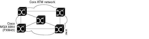
Figure 1-1 shows the switch operating in a core switch topology.
Figure 1-1 Core Switch Topology
In the core switch topology, the switch works with other ATM switches to transfer broadband ATM traffic from one ATM edge device to another. The core acts like a freeway, and the edge devices act like freeway on-ramps.
Note
Typically, core edge nodes communicate with multiple external nodes over relatively slow broadband trunks such as DS3, OC-3, and STM-1 trunks. The internal core node communicates with other core nodes using relatively fast links such as OC-12, OC-48, and STM-16 trunks.
Multiservice Edge Aggregation
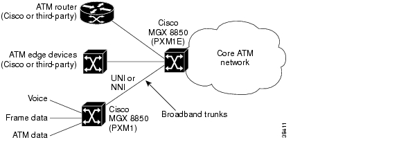
Figure 1-2 shows an MGX switch operating in a multiservice edge aggregation topology.
Figure 1-2 Multiservice Edge Aggregation Topology
The Cisco MGX 8850 (PXM1) node in Figure 1-2 is called a feeder node. In the multiservice edge aggregation topology, the feeder node is co-located with other ATM equipment and communicates with one or more core switches at remote locations. The switch aggregates the traffic from local ATM devices and packages it for high-speed communications over the core.
The Cisco MGX 8850 (PXM45) and the Cisco MGX 8950 switches are full PNNI and MPLS routing switches and they support feeder nodes. Cisco MGX 8850 (PXM1E) and Cisco MGX 8830 switches act as full PNNI routing switches, and must run software Release 3 or later. Cisco MGX 8850 (PXM1E) and Cisco MGX 8830 switches only support feeder connections to IGX nodes.
Typically, multiservice edge nodes communicate with colocated ATM devices over relatively slow broadband trunks such as DS3 and E3 trunks. The multiservice edge node communicates with core nodes using relatively fast links such as OC-12, OC-48, and STM-16 trunks.
Cisco MGX edge nodes also support virtual trunks as shown in Figure 1-3.
Figure 1-3 Virtual Trunk Topology
A virtual trunk provides a private virtual network path through an independent network such as a public ATM network. Using virtual trunks, Company A can establish a private virtual path between two sites using a public ATM network that supports this feature. From Company A's point of view, it has a private virtual path between the two sites that can support multiple virtual circuits (VCs). Company A's network topology is completely private, as all communications are simply passed between edge devices, with no need for translation or routing. To accomplish this configuration, the virtual trunk supports the Service Specific Connection Oriented Protocol (SSCOP) (virtual channel identifier [VCI = 5]), Private Network-to-Network Interface (PNNI) (VCI = 18) and Integrated Local Management Interface (ILMI) (VCI = 16) signaling protocols.
Figure 1-3 shows two virtual trunks, Virtual Trunk A and Virtual Trunk B. At Private Switch A, both virtual trunks use the same line to connect to the core ATM network. Within the core ATM network, soft virtual permanent paths (SPVPs) are defined to enable direct communications between the core edge nodes. The result is that Private Switch A has virtual trunks to Private Switches B and C and communicates with them as though they were directly connected.
DSL Aggregation
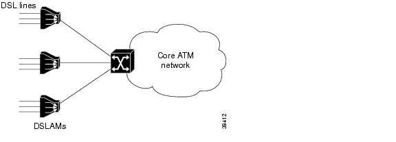
Figure 1-4 shows an MGX switch operating in a Digital Subscriber Line (DSL) edge aggregation topology.
Figure 1-4 DSL Edge Aggregation Topology
In the DSL edge aggregation topology, the switch is colocated with Digital Subscriber Line Access Multiplexers (DSLAMs) and communicates with one or more core switches at remote locations. The switch aggregates the DSL traffic from multiple DSLAMs and packages it for high-speed communications over the core.
Typically, DSL edge nodes communicate with colocated DSLAMs over relatively slower broadband trunks such as DS3 and E3 trunks. The DSL edge node communicates with core nodes using relatively faster links such as OC-3, OC-12, and OC-48 trunks.
Configuration Overview
Switch configuration is easier if you are familiar with the overall configuration process. To configure and start up the switch, you need to do some or all of the following tasks:
•
•
•
•
•
The sections that follow describe how to collect or create the information you need to complete these tasks.
Collecting Information
During configuration, you will need to enter general configuration data that describes the switch, enables administrator access, and enables switch participation in the network. This data includes
•
The following sections describe these topics in more detail. "Hardware Survey and Software Configuration Worksheets," provides tables that you can use to record the data you develop during configuration planning.
Unique Switch Name
Each switch must have its own name (which consists of up to 32 characters), unique within the ATM network. If you are adding a switch to a network, find out if the network administrator has established switch naming conventions, and find out which names have already been used. It is a good practice to name switches according to location, as such names convey both the switch identity and its location. The procedure for setting the name is described in the " Setting and Viewing the Node Name" section in Chapter 3, "Configuring General Switch Features."
IP Addressing Plan
An IP network addressing plan is required for switch management. IP network addressing is described in the " Guidelines for Creating an IP Address Plan" section later in this chapter.
ATM Addressing Plan
An ATM network addressing plan is critical for successful operation of MGX switches in an ATM network. PNNI networks require unique ATM addresses on each switch. However, the PNNI protocol uses structured network addresses to logically group network devices and determine routes between devices. For PNNI networks, an ATM address plan is required.
PNNI network addressing is described in the PNNI Network Planning Guide for MGX and SES Products.
Administrator Data
In most cases, more than one administrator will manage the switch. The MGX switches support multiple administrators and several different administration levels. As part of the planning process, you might identify who will manage the switch and at what level. You can learn more about managing administrators by reading the " Configuring User Access" section in Chapter 3, "Configuring General Switch Features."
Network Clock Source Plan
A network clock source plan is recommended for switch synchronization. IP network addressing is described in the " Guidelines for Creating a Network Clock Source Plan" section later in this chapter.
Network Management Plan
You can use the following tools to manage the Cisco MGX switches:
•
•
•
•
The CLI that comes with the switch is the least expensive option. To use the other tools, you must purchase Cisco WAN Manager (CWM) or a Simple Network Management Protocol (SNMP) manager. The MGX switches come with an SNMP agent for use with an SNMP manager.
The advantage to using CWM or an SNMP manager is that you can use one program to simultaneously manage multiple devices. Also, CWM is the only management tool that can configure Service Class Templates (SCTs). Most installations require at least one CWM workstation to complete the switch configuration.
CiscoView is a CWM component that can be used independently of CWM to provide limited monitoring and management capabilities.
To determine which versions of CWM and CiscoView are compatible with this release, refer to the Release Notes for Cisco MGX 8850 (PXM1E/PXM45), Cisco MGX 8950, and Cisco MGX 8830, Software Version 4.0.00.
For information on managing the switch with an SNMP manager, refer to the Cisco MGX 8850 SNMP Reference, Release 4.
Line and Trunk Data
When configuring lines and trunks that connect the switch to other devices, you need to collect the following information:
•
•
The MGX switches support many of the most common ATM configuration parameters. To configure lines and trunks, be sure that the configuration settings used on the switch match the configuration settings used at the other end of the line or trunk. In some cases, options you want to use at one end of the trunk are not supported at the other end. In these situations, change your configuration plan to use settings that are supported at both ends.
Guidelines for Creating an IP Address Plan
This section discusses local connectivity through the PXM LAN port. For information on using terminal servers, modems and CWM to remotely access the switch, see "Supporting and Using Additional CLI Access Options."
You can access the switch through three types of user interfaces: CLI, SNMP, and CWM. The switch has local ports in support of these interfaces, and each of these ports has a user-configurable IP address. The local ports are as follows:
•
•
•
•
Basic switch configuration and management can be completed by using a local terminal connected to the console port. However, to configure and manage the switch from a LAN connection, a modem connection, or with CWM, you need define an IP address for the appropriate interface.
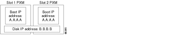
A typical switch configuration requires either one or two IP addresses for LAN access. When the switch hosts a single PXM card, use just one IP address and assign it to both the boot and LAN IP address options (more on this later in this section). When the switch uses two PXM cards, you can use one or two IP addresses. Figure 1-5 shows a redundant PXM configuration that uses two IP addresses. In a Cisco MGX 8850 (PXM1E/PXM45) or Cisco MGX 8950 switch, the redundant PXM cards would be in slots 7 and 8. In a Cisco MGX 8830 switch, the redundant PXM cards would be in slots 1 and 2.
Figure 1-5 Using Multiple IP Addresses for Switch Access
The configuration shown in Figure 1-5 provides the following results:
•
•
•
•
When different IP addresses are used for the boot and LAN IP addresses, you can manage the active PXM card and the switch using the LAN or disk IP address, which is B.B.B.B in Figure 1-5. You can also access the standby PXM card using the boot IP address. When the same address is used for both the boot and LAN IP addresses, that address can be used only to manage the active PXM card.
When planning IP addresses for your switch, use the following guidelines:
•
•
•
•
•
For instructions on setting boot and LAN IP addresses, see the " Setting the LAN IP Addresses" section in Chapter 3, "Configuring General Switch Features."
Guidelines for Creating a Network Clock Source Plan
Clock synchronization in an ATM network is very important. If two switches have trouble synchronizing their communications, traffic between the switches may have excessive errors or line failures. MGX switches support two methods of network clock synchronization:
•
•
Both of these methods of clock synchronization are described in the sections that follow.
Note
Note
Planning for Manual Clock Synchronization
In manual clock source configurations, you need to configure a primary and secondary clock source, which are distributed throughout the network. The secondary clock source takes over if the primary clock source fails. You can configure a network setup with one master clock source, and a secondary to ensure network clock stability. The secondary clock source takes over if the primary master clock source fails. Figure 1-6 shows an example network clock source topology.
Figure 1-6 Example Network Clock Source Topology with a Single Master Clock Source
In Figure 1-6, Switch 1 provides the master network clock source to the rest of the network and uses highly accurate external Building Integrated Timing System (BITS) clock sources to time its transmissions. These BITS clock sources are T1 or E1 lines with Stratum-1, 2, or 3 clock signals. Switch 1 uses one BITS line as the primary clock source and uses the secondary BITS source only if a failure occurs on the primary BITS line. If the primary BITS line fails and recovers, the switch reverts to the primary clock source if the revertive option was set when the primary clock was configured. If the revertive option was not set, you must manually re-configure the primary clock. When the revertive option is disabled, the switch reverts back to the primary clock source only if the secondary clock source fails.
Switches 2 through 5 synchronize to Switch 1 with the master clock signal, which they receive over PXM1E or AXSM lines. Switch 6 synchronizes its communications using the master clock source, which is forwarded from Switch 3. In this topology, all switches synchronize to the same clock source, and this configuration reduces the possibility that two switches might not be able to synchronize communications.
Figure 1-7 shows an example network clock source topology that uses master clock sources on different switches.
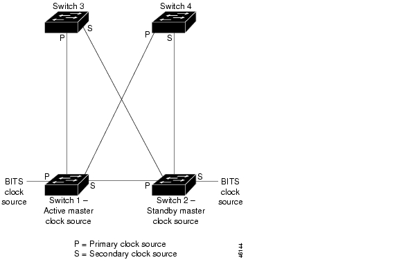
Figure 1-7 Example Network Clock Source Topology with Two Master Clock Sources
In Figure 1-7, Switches 1 and 2 have BITS devices. Switch 1 operates as the master and distributes its BITS clock source over PXM1E or AXSM lines to Switches 2 through 4. Switch 2 is the standby master and receives its primary clock signal over the PXM or AXSM line from Switch 1. As long as Switch 1 and its primary BITS clock source are operating correctly, the entire network is synchronized to the BITS clock source from Switch 1.
In Figure 1-7, the secondary clock source for the network is the Switch 2 BITS clock source, and all other switches are configured to use the PXM1E or AXSM lines from Switch 2 as their secondary clock source. If Switch 1 or its BITS clock source fails, all the switches start using the clock signals from Switch 2 for network communications. This configuration preserves network sychronization when either a clock source or a switch fails.
To develop a network clock source plan, create a topology drawing and identify which switches serve as active and standby master clock sources. For each switch that receives clock sources from other switches, indicate the lines that carry the primary and secondary clock signals.
Consider the following information when you create your manual network clock source plan:
•
•
•
•
•
•
•
•
•
Planning for NCDP Synchronization
The MGX switches support a Network Clock Distribution Protocol (NCDP), which selects the best clock in your network based on your configuration, and automatically configures the path to that clock for each node throughout your network. In an NCDP clock configuration, there are no primary and secondary clock sources. Instead, you configure several clock sources for the nodes in your network, from which NCDP selects the best (or root) and second best clock source for the network. Once NCDP has selected the root clock source, it is propagated to all the nodes in the network so that all nodal clocks are synchronized. If the root clock source fails, the second best clock source becomes the root clock source. If the second best clock source fails, NCDP selects the third best clock source to take over as the root clock source, and so forth.
If you want to use NCDP to set up your network clocks, you must first enable NCDP, as described in the "Managing NCDP Clock Sources" section in Chapter 13, "Switch Operating Procedures." Once you enable NCDP on your node, it is automatically enabled on all NNI ports on the node. When NCDP is enabled, a root clock source is automatically selected and distributed to all nodes in the network that have NCDP enabled. NCDP automatically selects an internal oscillator on one of the NCDP nodes to be the root clock source. Each NCDP node in the network is synchronized to this root clock reference. If you do not want the root clock source to be an internal oscillator, you can configure it to come from an external source with the cnfncdpclksrc command, as described in the "Managing NCDP Clock Sources" section Chapter 13, "Switch Operating Procedures."
NCDP uses the following criteria to find the best root clock source for the network:
•
•
•
•
You can modify the clock priority, stratum level of the Bits source, and clock source reference through the cnfncdpclksrc command, as described in the "Managing NCDP Clock Sources" section in Chapter 13, "Switch Operating Procedures."
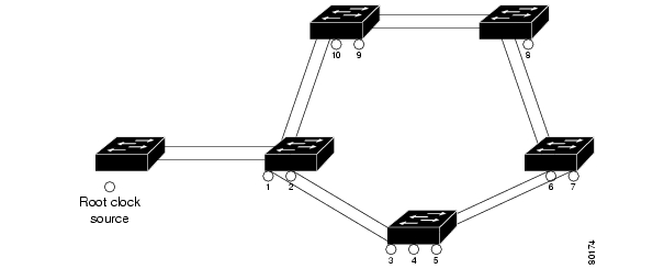
Figure 1-8 shows an example NCDP network clock source topology. The numbers represent the priority of each network clock source, with 1 being the highest priority (or second best clock source) and 10 being the lowest priority. In this example, if the root clock source fails, the clock source with priority 1 takes over as the root clock. If the new root clock source with priority 1 fails, then the clock source with priority 2 takes over as the root, and so forth.
Figure 1-8 Example NCDP Source Topology
Consider the following information when you create your NCDP network clock source plan:
•
•
•
•
•
•
•
•
•
•
•
To develop an NCDP network clock source plan, create a topology drawing and identify all the configured clock sources on each switch in the network. Identify the priority of each clock source. You may also want to identify any NNI ports where you plan to disable NCDP.
![]()
![]()
![]()
![]()
![]()
![]()
![]()
![]()
Posted: Thu May 31 17:13:22 PDT 2007
All contents are Copyright © 1992--2007 Cisco Systems, Inc. All rights reserved.
Important Notices and Privacy Statement.