|
|

Table Of Contents
Planning for Card Redundancy, Line Redundancy, and Bulk Distribution
Planning Standalone and Redundant Card Configurations
Standalone Card Configuration Guidelines
1:1 Redundant Card Configuration Guidelines
1:N Redundant Card Configuration Guidelines (Except RPM)
1:N Redundant Card Configuration Guidelines for RPM
Planning Standalone and Redundant Line Configurations
Standalone Line Configuration Guidelines
Redundant Line Configuration Guidelines
Planning for Bulk Distribution
2
Planning for Card Redundancy, Line Redundancy, and Bulk Distribution
This chapter describes how to plan for card redundancy, line redundancy, and bulk distribution on MGX switches. The card redundancy feature uses a secondary card of the same type to serve as a standby card and take over if the active card fails. The line redundancy feature extends this same type of fault tolerance to individual lines connected to the switch.
Bulk distribution is a feature that uses an SRM card to concatenate T1 or E1 traffic from selected service modules and transmit that traffic over higher speed back cards connected to the SRM. Concatenated traffic received at the SRM cards is distributed to the individual service modules. The primary feature of bulk distribution is that it enables a switch to use fewer T3 or OC-3 lines instead of many T1 or E1 lines. A secondary benefit is that SRME cards can provide line redundancy to cards that otherwise could not use that feature.
Because a configuration change for any of these services has the potential to interrupt service and can require substantial configuration teardown, it is important to develop a plan for these services early. This plan determines how controller cards and service modules must be installed in the chassis, and how lines must connect to the cards before configuration starts. Once the hardware is installed, the software configuration team uses this plan to configure the switch. For the switch to operate properly, the software configuration must match the hardware configuration.
The features described in this chapter are not supported on all cards. Table 2-1 lists all the card types and the features they support.
Table 2-1 Card Redundancy, Line Redundancy, and Bulk Distribution Features for Each Card
AUSM8T1/B
AUSM8E1/BStandalone
None
Yes
1:N
AXSM-1-2488
AXSM-1-2488/B
AXSM-1-9953-XGStandalone
None
No
1:1
Intercard APS
AXSM-2-622-E
Standalone
Intracard APS
No
1:1
Intercard and intracard APS
AXSM-4-622
AXSM-4-622/B
AXSM-4-2488-XGStandalone
Intracard APS
No
1:1
Intercard and intracard APS
AXSM-8-155-E
Standalone
Intracard APS
No
1:1
Intercard and intracard APS
AXSM-16-155
AXSM-16-155/BStandalone
Intracard APS
No
1:1
Intercard and intracard APS
AXSM-16-T3E3
AXSM-16-T3E3/B
AXSM-16-T3E3-E
AXSM-32-T1E1-EStandalone
Intracard APS
No
1:1
Intercard and intracard APS
CESM-8E1
CESM-8T1
CESM-8T1/BStandalone
None
Yes
1:N
FRSM-2CT3
FRSM-2T3E3Standalone
None
No
1:1
FRSM-8E1
FRSM-8E1-C
FRSM-8T1
FRSM-8T1-CStandalone
None
Yes
1:N
FRSM-12-T3E3
Standalone
None
No
1:1
FRSM-HS2/B
Standalone
None
No
1:11
PXM1E-4-155
PXM1E-8-155Standalone
Intracard APS
No
Preconfigured 1:1
Intercard and intracard APS
PXM1E-8-T3/E3
PXM1E-16-T1/E1Standalone 1:1
None
No
Preconfigured 1:1
PXM1E COMBO
Standalone
Intracard APS
No
Preconfigured 1:1
Intercard and intracard APS
PXM45
Standalone
None
No
Preconfigured 1:1
SRM-3T3
Standalone
None
Yes
Preconfigured 1:1
SRME
Standalone
None
Yes
Preconfigured 1:1
Intercard APS
VISM-PR-8E1
VISM-PR-8T1Standalone
None
Yes
1:N
RPM-PR-256
RPM-PR-512
RPM-XF-512Standalone
None
No
1:N without SRM
1 1:1 redundancy supported only with the SCSI2-2HSSI/B back card and a FRSM-HS1/B HSSI Y-cable. 1:1 redundancy is not supported in slots that use the 12IN1-8S back card.
Planning Standalone and Redundant Card Configurations
Whenever you configure a PXM card or service module, it will operate in either standalone mode or redundant mode, depending on the card type, the other cards in the switch, and the configuration you apply to that card. The following subsections provide planning guidelines for using cards in standalone and redundant configurations.
Standalone Card Configuration Guidelines
When a card is inserted in a switch without a standby or redundant card, it is said to be working in standalone mode. If a standalone card goes down, all the connections on that card will fail and traffic will be lost. All cards that can be installed in an MGX switch can operate in standalone mode. However, Cisco recommends configuring redundancy in order to ensure that you will not lose traffic and connectivity in the event of a card or line failure.
All Cisco MGX switch cards operate in the standalone configuration without additional configuration. Standalone configurations are often used in lab environments or other non-critical applications.
In the standalone configuration, the appropriate back cards must be installed according to the following guidelines:
•
For all PXM cards, both back cards must be installed
•
•
•
SRM cards are optional and add 1:N card redundancy, bulk distribution, and bit error rate testing (BERT) services to a Cisco MGX switch. These services apply to select service modules, so in a Cisco MGX 8850 (PXM45) switch, for example, you can install a standalone PXM and still support 1:N card redundancy for select service modules.
When you install SRM cards, it is important to note the relationship between the SRM cards and the PXM cards, which is shown in Table 2-2. For example, in a Cisco MGX 8850 (PXM1E) switch, the PXM in slot 7 is preconfigured to work with SRMs in slots 15 and 31. The SRM in slot 15 provides SRM services to the upper bay, and the SRM in slot 31 provides SRM services in the lower bay.
Because the relationship between PXM and SRM cards is preconfigured and cannot be changed, it is wise to verify that the standalone PXMs and SRMs have been installed correctly before you start configuring a switch. Use the following guidelines when verifying the installation of PXM and SRM cards:
•
•
•
•
•
1:1 Redundant Card Configuration Guidelines
The 1:1 redundant card configurations provide the optimum protection against failure of a single card. In the 1:1 redundant card configuration, one card operates in the active mode and a second card operates in standby mode, ready to provide services in the event of an active card failure. To minimize switchover time and prevent service interruption, standby cards are dedicated to a single active card and cannot support additional cards. Standby cards do not support services until they transition to the active state.
Note
There are two types of 1:1 redundant card configurations on Cisco MGX switches, preconfigured redundancy and configured redundancy. The following sections describe these redundancy types and provide guidelines for their configuration.
Note
Preconfigured Redundancy (PXM and SRM)
Cisco MGX switches are preconfigured to support redundant PXM and SRM cards. If you want to use redundant PXM and SRM cards, simply install cards in the appropriate slot as described in Table 2-3.
SRM cards are optional and add 1:N card redundancy, bulk distribution, and bit error rate testing (BERT) services to a Cisco MGX switch. These services apply to select service modules, so in a Cisco MGX 8850 (PXM45) switch, for example, you might use 1:1 card redundancy for some cards and 1:N redundancy for others.
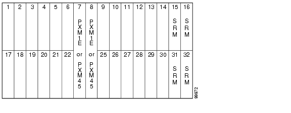
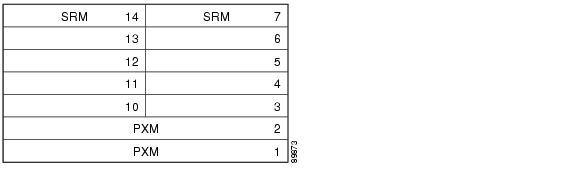
When you install SRM cards, it is important to note the relationship between the SRM cards and the PXM cards, which is shown in Table 2-3. For example, in a Cisco MGX 8850 (PXM1E) switch, the primary preconfigured card set is a PXM in slot 7, an SRM covering the upper bay in slot 15, and an SRM covering the lower bay in slot 31. The secondary configuration is a PXM in slot 8, an SRM covering the upper bay in slot 16, and an SRM covering the lower bay in slot 32. If the primary card set fails, a switchover to the secondary card set is initiated. Figure 2-1 and Figure 2-2 show the card positions for PXM and SRM cards in the switches that support SRM cards.
Figure 2-1 Cisco MGX 8850 Switch with Redundant PXMs and SRMs
Figure 2-2 Cisco MGX 8830 Switch with Redundant PXMs and SRMs
Because the relationship between PXM and SRM cards is preconfigured and cannot be changed, it is wise to verify that redundant PXMs and SRMs have been installed correctly before you start configuring a switch. Use the following guidelines when verifying the installation of PXM and SRM cards:
•
•
•
•
•
•
•
Configured 1:1 Card Redundancy
Configured 1:1 card redundancy operates much like 1:1 PXM redundancy. The difference is that the redundancy is not preconfigured. To use configured 1:1 card redundancy with cards such as AXSM, FRSM12, and FRSM-2CT3 cards, you must configure two identical cards to be a redundant pair. After configuration, one card operates in active mode, and the other card operates in standby mode. If the active card fails, the standby card takes over, and no calls are lost.
Note
When planning a configured 1:1 card redundancy configuration, consider the following:
•
•
•
•
•
1:N Redundant Card Configuration Guidelines (Except RPM)
1:N card configurations use one standby card to back up multiple active cards. If an active card fails, the standby card loads the proper configuration and takes over operation for the active card. Once the standby card transitions to the active mode, it is no longer available to back up other active cards.
With the exception of 1:N redundant configurations on RPM cards, 1:N redundant card configurations always require the services of one or more SRM cards. SRM cards support 1:N redundancy in the following modes:
•
•
The following subsections describe how 1:N redundancy operates in these two configurations and provide guidelines for 1:N redundant configurations.
1:N Redundancy Without Bulk Distribution
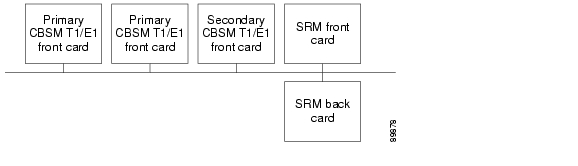
When 1:N redundancy is used without bulk distribution, a special redundancy back card is installed for each 1:N redundant card set as shown in Figure 2-3. This redundancy back card has no connectors on it and is installed behind the standby card. If an active card in the 1:N redundant card set fails, the standby card takes over, and the SRM routes communications from the standby back card through the special redundancy back card, and over to the back card behind the failed card. This configuration allows the standby card to use the lines connected to the back card behind the failed active card.
Figure 2-3 Example 1:N Redundant Configuration without Bulk Distribution
The rerouting of the line communications takes place over a single redundancy bus, one of which is installed in each bay of a Cisco MGX switch. A Cisco MGX 8830 switch has one redundancy bus, and a Cisco MGX 8850 (PXM1E/PXM45) switch has two, one for each bay. The redundancy bus is available to only one 1:N redundant card set at a time, so if any 1:N protected card fails in a bay, the redundancy bus is unavailable to all other 1:N redundant card sets.
Your use of 1:N redundancy is determined in part by the hardware installation. Use the following guidelines when verifying the installation of service modules that will use 1:N redundancy without bulk distribution:
•
•
•
•
•
1:N Redundancy With Bulk Distribution
Bulk distribution is an SRM card feature that combines communications paths from multiple T1 or E1 lines on individual service modules and forwards those communications over T3 or OC-3 lines connected to SRM back cards. Communications received over the SRM T3 or OC-3 lines are separated into individual T1 or E1 data streams and forwarded to the appropriate service module. Bulk distribution enables you to use one T3 or OC-3 line for service module communications instead of multiple T1 or E1 lines.
When 1:N redundancy is used with bulk distribution, no back cards are installed behind service modules in a 1:N redundant card set. All communications lines for the protected cards are rerouted through the backplane to the SRM back card as shown in Figure 2-4.
Figure 2-4 Example 1:N Redundant Configuration with Bulk Distribution Enabled
If an active card in the 1:N redundant card set fails, the standby card takes over, and the SRM routes communications from the standby back card to the appropriate logical lines within the SRM T3 or OC-3 line. When bulk distribution is used, the 1:N redundant card set does not use the redundancy bus on the backplane, so the SRM can support failures in multiple 1:N redundant card sets.
Your use of 1:N redundancy is determined in part by the hardware installation. Use the following guidelines when verifying the installation of service modules that will use 1:N redundancy with bulk distribution:
•
•
•
•
•
•
•
•
1:N Redundant Card Configuration Guidelines for RPM
RPM-PR and RPM-XF cards can operate in 1:N redundant card configurations without the services of SRM cards. In this configuration type, one standby RPM card takes over if any active RPM in the redundant card set fails. For more information, refer to Cisco MGX Route Processor Module (RPM-PR) Installation and Configuration Guide or Cisco MGX Route Processor Module (RPM-XF) Installation and Configuration Guide.
Note
Planning Standalone and Redundant Line Configurations
Most cards support only standalone line configurations, but some cards, such as PXM1E, AXSM, and SRME also support redundant lines. Table 2-1 lists all the card types and indicates which cards support redundant line configurations. The following subsections provide information you need to know when planning standalone and redundant line configurations.
Standalone Line Configuration Guidelines
Standalone line configurations can be used to support standalone or redundant card configurations. However, the standalone line configuration you use will be dependent one of the following card configurations:
•
•
•
•
Standalone Card Configurations
Establishing a standalone line for a standalone card configuration is easy. This is the default configuration for every line, so no special configuration is required, unless you need to match communications parameters with the device at the other end of the line. When verifying the hardware installation for standalone line on a standalone card, consider the following guidelines:
•
•
1:1 Redundant Card Configurations
Establishing a standalone line for a 1:1 redundant card configuration is easy. This is the default configuration for every line, so no special configuration is required, unless you need to match communications parameters with the device at the other end of the line. When verifying the hardware installation for standalone line for a 1:1 redundant card configuration, consider the following guidelines:
•
•
•
–
–
–
Note
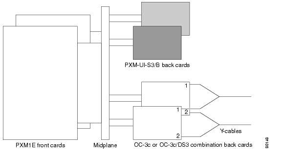
Figure 2-5 shows how redundant PXM1E cards use a Y-cable to connect to standalone lines.
Figure 2-5 Redundant PXM1E Configuration with Standalone Lines
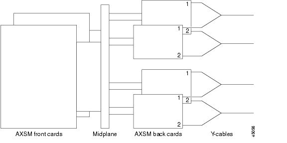
Figure 2-6 shows how redundant AXSM cards connect to standalone lines. Other service modules that support 1:1 card redundancy, such as FRSM12 and FRSM-HS2/B, use Y-cables in a similar manner.
Figure 2-6 Redundant AXSM Configuration with Standalone Lines
Note
1:N Redundant Card Configurations (Except RPM)
Establishing a standalone line for a 1:N redundant card configuration is easy. This is the default configuration for every line, so no special configuration is required, unless you need to match communications parameters with the device at the other end of the line. When verifying the hardware installation for a standalone line in a 1:N redundant card configuration, consider the following guidelines:
•
•
•
•
1:N Redundant RPM Configurations
The method you use for connecting multiple RPMs to a single network will depend on the back card type. For example, if you are configuring two RPM-PRs for 1:N redundant operation over a connection to a single Ethernet 10/100 network, you would directly connect the corresponding ports or lines to a hub on that network. You would not use a Y-cable.
For more information on preparing RPM cards for 1:N redundancy, refer to Cisco MGX Route Processor Module (RPM-PR) Installation and Configuration Guide or Cisco MGX Route Processor Module (RPM-XF) Installation and Configuration Guide.
Redundant Line Configuration Guidelines
Redundant line configurations extend fault tolerance to individual lines. As with redundant cards, redundant lines operate as a pair. If one line fails, the second line in the redundant pair takes over.
Cisco MGX switches use Automatic Protection Switching (APS) to provide line fault tolerance. APS is a component of SONET and is therefore available only on optical interfaces on the following cards:
•
•
•
Table 2-1 lists all the card types and the line configuration options they support.
Note
When you configure APS, you must define a working line and a protection line for each redundant line pair. The working line is the primary or preferred line, and communications take place over that line as long as the line remains operative. Even when the working line and protection lines are on different cards and a switchover occurs between the front cards, the working line remains active unless the working line itself fails.
If a failure occurs on the working line, APS initiates a switchover to the protection line. The revertive option allows you to control what happens when a failed working line recovers. If the revertive option is enabled, the working line will become active after a configurable period of time. If the revertive option is disabled, you must manually switch over from the protective line to the working line after the working line recovers.
Cisco MGX switches support two types of APS: intracard APS and intercard APS. The following subsections describe these two APS options and provide guidelines for planning APS configurations.
Intracard APS Configurations
Intracard APS configurations are created with the working and protection lines on the same back card. As shown in Figure 2-7, intracard APS makes it possible to have redundant line protection for a standalone card configuration.
Figure 2-7 Standalone PXM1E with Intracard APS
Figure 2-8 shows how a standalone AXSM connects to redundant lines.
Figure 2-8 Standalone AXSM with Intracard APS
Note
Because the front cards are far more complex and expensive than the back cards, intracard APS is not practical on 1:1 redundant card installations because the use of intracard APS cuts the available port count in half. When planning an intracard APS configuration, consider the following requirements:
•
•
•
•
•
•
Intercard APS Configurations
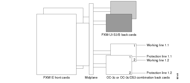
Intercard APS configurations are created with the working and protection lines on different back cards. As shown in Figure 2-9, intercard APS makes it possible to extend the fault tolerance provided by redundant front cards to back cards and lines.
Figure 2-9 Redundant PXM1E Configuration with Intercard APS
Back card and line fault tolerance is provided by intercard APS. If the working line or the back card to which it is connected fails, communications traffic is rerouted through the protection line and the back card to which it is connected.
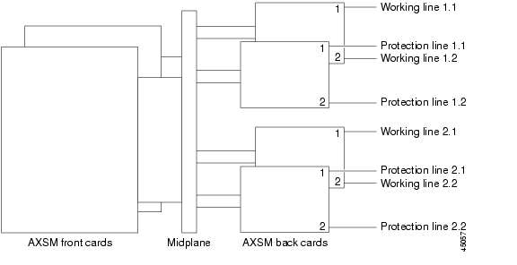
Figure 2-10 shows how a redundant AXSM card set uses intercard APS.
Figure 2-10 Redundant AXSM Configuration with Intercard APS
Figure 2-11 shows redundant SRMEs using intercard APS.
Figure 2-11 Redundant SRMEs with Intercard APS
When planning a redundant line configuration that uses intercard APS, consider the following requirements:
•
•
•
•
•
•
•
•
•
•
Table 2-4 describes the APS hardware requirements for PXM1E card sets.
Planning for Bulk Distribution
Bulk distribution is a feature that uses an SRM card to concatenate T1 or E1 traffic from selected service modules and transmit that traffic over higher speed back cards connected to the SRM. Concatenated traffic received at the SRM cards is distributed to the individual service modules. The primary feature of bulk distribution is that it enables a switch to use fewer T3 or OC-3 lines instead of many T1 or E1 lines. A secondary benefit is that SRME cards can provide line redundancy to cards that otherwise could not use that feature.
When planning for bulk distribution, consider the following guidelines:
•
•
•
•
•
•
•
•
![]()
![]()
![]()
![]()
![]()
![]()
![]()
![]()
Posted: Thu May 31 17:06:57 PDT 2007
All contents are Copyright © 1992--2007 Cisco Systems, Inc. All rights reserved.
Important Notices and Privacy Statement.