|
|

After you have configured the SwitchProbe device as described in "Initializing a SwitchProbe Device," you are ready to connect the device to the network.
This chapter provides detailed instructions for connecting the interfaces on the SwitchProbe device to the network.
The following interfaces are discussed in this chapter:
Before connecting the SwitchProbe device to the network, note the following warnings and cautions:
 | Warning Before working on equipment that is connected to power lines, remove jewelry (including rings, necklaces, and watches). Metal objects heat up when connected to power and ground and can cause serious burns or weld the metal object to the terminals. |
The following interfaces are class 1 laser products:
Read the following warnings for interfaces with class 1 laser products:
| Warning Because invisible laser radiation may be emitted from the aperture of the port when no cable is connected, avoid exposure to laser radiation and do not stare into open apertures. |
 | Caution To prevent possible damage to the SwitchProbe device, read "Site Requirements." |
| Caution To prevent network interruptions, make sure all Token Ring or WAN interfaces are configured to the correct speed. |
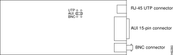
The Ethernet interface supports Thicknet, Thinnet, or unshielded twisted pair (UTP) cable types; the device is set to one of the three types when it is manufactured. A label in the lower portion of the device front panel indicates the factory-set configuration.
Table 6-1 describes the label and corresponding connection.
| If the Label States... | You Connect |
|---|---|
Configured for AUI | A Thicknet (10Base5) cable to the Thicknet connector. |
Configured for BNC | A Thinnet (10Base2) cable to the Thinnet connector. |
Configured for UTP | A UTP cable to the RJ-45 UTP connector. |
Table 6-2 describes the LEDs on the Ethernet interface.
| LED Position | LED Color | Status | Meaning |
|---|---|---|---|
Green | On | Link signal detected. | |
|
| Amber | On | Heavy network traffic. |
Figure 6-1 shows the Ethernet interface LEDs.

To set the Ethernet connection, you must change an internal jumper on the Ethernet interface card.
To change the Ethernet connection type, see Figure 6-2 and follow these steps:
| Warning Do not work on the system or connect or disconnect cables during periods of lightning activity. |
| Warning Before working on a system that has an on/off switch, turn OFF the power and unplug the power cord. |
Step 1 Remove the screws and open the unit.
Step 2 Hold the cover in place and gently slip it off.
| Warning Do not touch the power supply when the power cord is connected. For systems with a power switch, line voltages are present within the power supply even when the power switch is off and the power cord is connected. For systems without a power switch, line voltages are present within the power supply when the power cord is connected. |
Step 3 Remove the network interface card.
The jumper is located on the board behind the connectors.
Step 4 Place the jumper on the selected option: UTP, AUI, or BNC.
For the Multiport 10BaseT Ethernet interface, connect a category 5 UTP cable into the RJ-45 port on the interface.
Each Multiport Fast Ethernet interface contains LEDs.
Table 6-3 describes the Fast Ethernet TX interface LEDs.
| LED | Color | Status | Meaning |
|---|---|---|---|
100 | Green | On | Port is active and monitoring a 100 Mbps Fast Ethernet network. |
ACT | Amber | On | Heavy traffic on the network. |
10 | Green | On | Port is active and monitoring a 10 Mbps Ethernet network. |
Table 6-4 describes the Fast Ethernet FX interface LEDs.
| LED | Color | Status | Meaning |
|---|---|---|---|
LINK | Green | On | Port is active and monitoring a 100 Mbps Fast Ethernet network. |
ACT | Amber | Off | No transmit activity. |
For the Fast Ethernet half-duplex 100BaseTX interface, connect a category 5 UTP cable into the RJ-45 port on the interface.
For the Fast Ethernet half-duplex 100BaseFX interface, connect a SC-to-SC
62.5/125 micron multimode fiber-optic cable into the SC modular port on the interface.
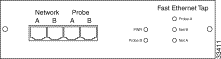
The Fast Ethernet Full-Duplex 100BaseTX SwitchProbe device includes a Fast Ethernet TX tap to monitor full-duplex network links.
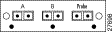
The Fast Ethernet Full-Duplex TX tap (Figure 6-3) contains two Network ports (Net A and Net B) and two Probe ports (Probe A and Probe B).
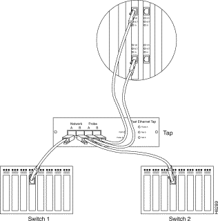
To connect the full-duplex 100BaseTX interfaces to two switches, see Figure 6-4 and follow these steps:
Step 1 Connect a category 5 UTP straight-through cable into one of the two RJ-45 100BaseTX ports on the SwitchProbe Fast Ethernet interface.
| Warning To avoid electric shock, do not connect safety extra-low voltage (SELV) circuits to telephone-network voltage (TNV) circuits. LAN ports contain SELV circuits, and WAN ports contain TNV circuits. Some LAN and WAN ports both use RJ-45 connectors. Use caution when connecting cables. |
Step 2 Connect the other end of the category 5 UTP cable into the port labeled Probe A on the Fast Ethernet tap.
Step 3 Connect a category 5 UTP straight-through cable into the other RJ-45 100BaseTX port on the same Fast Ethernet interface.
Step 4 Connect the other end of the category 5 UTP cable into the port labeled Probe B on the Fast Ethernet tap.
Step 5 Connect a category 5 UTP straight-through cable into the port labeled
Network A on the Fast Ethernet tap.
Step 6 Connect the other end of the category 5 UTP cable into Switch 1.
Step 7 Connect a category 5 UTP straight-through cable into the port labeled
Network B on the Fast Ethernet tap.
Step 8 Connect the other end of the category 5 UTP cable into Switch 2.
Connecting the full-duplex 100Base FX interfaces of a Fast Ethernet SwitchProbe device to a network segment is a two-step process:
Step 1 Connect a fiber-optic splitter tap to the 100BaseFX interfaces on the SwitchProbe device.
Step 2 Connect the fiber-optic splitter tap to the network segment.
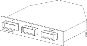
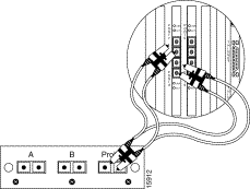
The Fast Ethernet FX SwitchProbe device requires a fiber-optic splitter tap, shipped with the device, to monitor the network. The splitter tap is passive—link integrity is maintained whether the device is on or off.
The fiber-optic splitter tap (Figure 6-5) contains three female SC duplex connection ports, labeled A, B, and Probe.
For instructions on installing the fiber-optic splitter tap, see "Installing a Splitter Tap in a Rack Panel (Optional)" and "Installing a Splitter Tap in a Rack Panel (Optional)" in "Installing a SwitchProbe Device."
The fiber-optic splitter tap kit shipped with the SwitchProbe device includes (among other cables) a four-foot SC-duplex-to-dual-SC-duplex multimode fiber cable.
To connect the SwitchProbe device to the tap, see Figure 6-6 and follow these steps:
Step 1 Insert the end of the fiber cable labeled DTE into the full-duplex 100BaseFX interface labeled DTE on the device.
Step 2 Insert the end of the fiber cable labeled DCE into the full-duplex 100BaseFX interface labeled DCE on the device.
Step 3 Insert the other end of the fiber cable (the cable with only one connector) into the interface labeled Probe on the fiber-optic splitter tap.
After you connect the SwitchProbe device to the tap, you can connect the tap to the network segment.
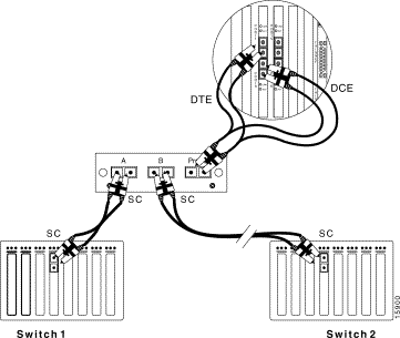
Depending on the type of cable you used between each switch and the tap, there are three possible configurations to connect the two switches to the fiber-optic splitter tap:
To connect a 100BaseFX network with SC connectors to a fiber-optic splitter tap, see Figure 6-7 and follow these steps:
Step 1 Use the SC-to-SC cable included with the SwitchProbe device to connect Switch 1 to interface A on the fiber-optic splitter tap.
Step 2 Connect Switch 2 to interface B on the fiber-optic splitter tap. Use the cable that was originally plugged into Switch 1.
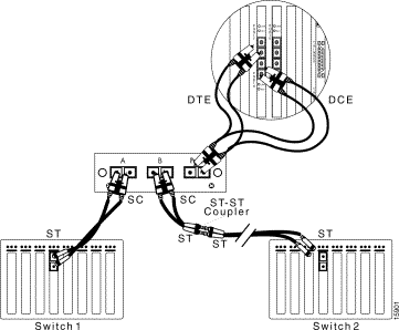
To connect a 100BaseFX network with ST connectors to a fiber-optic splitter tap, see Figure 6-8 and follow these steps:
Step 1 Use the SC-to-ST cable included with the SwitchProbe device to connect Switch 1 to interface A on the fiber-optic splitter tap. Plug the ST connector into Switch 1 and plug the SC connector into the tap.
Step 2 Use the other SC-to-ST cable included with the SwitchProbe device to connect the ST-to-ST coupler to interface B on the fiber-optic splitter tap. Plug the ST connector into the ST-to-ST coupler and plug the SC connector into the tap.
Step 3 Connect Switch 2 to the ST-to-ST coupler. Use the cable that was originally plugged into Switch 1.
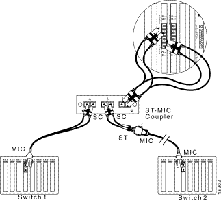
To connect a 100BaseFX network with MIC connectors to a fiber-optic splitter tap, see Figure 6-9 and follow these steps:
Step 1 Use the SC-to-MIC cable included with the SwitchProbe device to connect Switch 1 to interface A on the fiber-optic splitter tap. Plug the MIC connector into Switch 1 and plug the SC connector into the tap.
Step 2 Use the SC-to-ST cable included with the SwitchProbe device to connect the ST-to-MIC coupler to interface B on the fiber-optic splitter tap Plug the ST connector into the ST-to-MIC coupler and plug the SC connector into the tap.
Step 3 Connect Switch 2 to the ST-to-MIC coupler. Use the cable that was originally plugged into Switch 1.
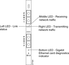
Each Gigabit Ethernet interface contains seven LEDs:
Table 6-5 describes the LEDs on the Gigabit Ethernet interface.
| LED Position | LED Color | Status | Meaning |
|---|---|---|---|
Green | On | Link signal detected. | |
Off | No link signal detected or no cable attached to port. | ||
Amber | On | Receiving heavy network traffic. | |
Blinking | Receiving moderate network traffic. | ||
Off | Receiving no network traffic. | ||
Right LED | Green | On | Transmitting heavy network traffic. |
Blinking | Transmitting moderate network traffic. | ||
Off (default) | Transmitting no network traffic. This LED is always off when interfaces are configured to monitor. | ||
Bottom LED | Amber | On | Gigabit Ethernet card diagnostics are complete. |
Off | Gigabit Ethernet card is not functioning properly or diagnostics not yet complete. |
Figure 6-10 shows the Gigabit Ethernet interface LEDs.
The way you connect the Gigabit Ethernet interface to a network segment depends on the type of segment to be monitored.
Some switches (such as the Cisco Catalyst 4000-, 5000, and 6000-series) have an auto-negotiate mode that allows a port on the switch to automatically negotiate the speed and mode (half- or full-duplex) of the device on the other side of the network segment. If the other side of the segment (for example, the Gigabit Ethernet SwitchProbe device) does not respond to the auto-negotiation, the switch assumes that there is no device at the other end, and shuts off the internal link.
Because this SwitchProbe device is designed to work in receive-only mode, it does not participate in any auto-negotiation in half-duplex mode. Therefore, the switch assumes there is no device attached to the other end of the network segment—even though the Gigabit Ethernet SwitchProbe device is physically attached to the switch SPAN port.
To work around this, you must disable auto-negotiation on the port to which the Gigabit Ethernet SwitchProbe device is physically connected.
For example, with a Cisco Gigabit Ethernet switch, you would enter the following command on the switch command line:
set port negotiation module_num/port_num disable
where module_num/port_num identifies the port on the switch connected to the Gigabit Ethernet SwitchProbe device.
This situation occurs only when a Gigabit Ethernet SwitchProbe device is directly attached (with no tap) to a Cisco Catalyst switch SPAN port.
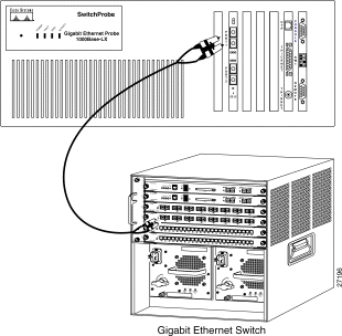
To connect the Gigabit Ethernet interface to a Cisco Catalyst switch, see Figure 6-11 and follow these steps:
Step 1 Locate an SC-to-SC fiber cable (with one male SC connector at each end) that was included with the SwitchProbe device.
Step 2 Remove all dust caps from the connectors at the ends of the cable.
Step 3 Plug one end of the SC-to-SC fiber cable into the Gigabit Ethernet switch, server, or router to be monitored.
Step 4 Plug the other end of the cable into one of the Gigabit Ethernet interface ports on the SwitchProbe device.
Connecting the Gigabit Ethernet interface to a full-duplex network segment is a two-stage process:
Step 1 Connecting the fiber optic splitter tap (shipped with the device) to the Gigabit Ethernet interface on the SwitchProbe device.
Step 2 Connect two Gigabit Ethernet devices to the fiber optic splitter tap (to accumulate statistics about data as it travels on the network segment).
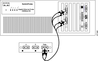
Figure 6-12 shows the front panel of a fiber optic splitter tap.
To connect a fiber optic splitter tap to the SwitchProbe device, see Figure 6-13 and follow these steps:
Step 1 Remove all dust caps from the fiber optic splitter tap connector ports.
Step 2 Locate the 9.84 foot (3 meter) fiber cable (with two male SC connectors at one end and one male SC connector at the other end) that was included with the tap.
Step 3 Remove all dust caps from the connectors at the ends of the cables.
Step 4 Plug the end of the fiber cable (labelled DCE) into port 1 of the Gigabit Ethernet interface (port 1 is the DCE port).
Step 5 Plug the end of the fiber cable (labelled DTE) into port 2 of the Gigabit Ethernet interface (port 2 is the DTE port).
Step 6 Plug the other end of the fiber cable (the one with a single connector) into the port labelled Probe on the fiber optic splitter tap.
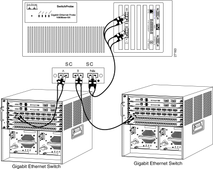
After you connect the Gigabit Ethernet interface on the SwitchProbe device to the tap, you must connect the tap to the network segment.
To do so, see Figure 6-14 and follow these steps:
Step 1 Locate the cable that currently connects one Gigabit Ethernet switch, server, or router to another Gigabit Ethernet switch, server, or router.
Step 2 Unplug this cable from one of the two Gigabit Ethernet devices.
Step 3 Plug the end of the cable (that you just unplugged) into the one of the two remaining female SC duplex ports on the tap (either port A or B).
Step 4 Locate an SC-to-SC fiber cable (with one male SC connector at each end).
Step 5 Plug one end of the SC-to-SC fiber cable into the second Gigabit Ethernet switch, server, or router.
Step 6 Plug the other end of the cable into the remaining female SC duplex port on the tap (A or B).
As illustrated in Figure 6-14, there should now be one cable extending from one Gigabit Ethernet switch, server, or router to the tap A port, and another cable from another Gigabit Ethernet switch, server, or router to the tap B port, and the tap should be connected to the SwitchProbe device.
The Token Ring interface supports both Type 1 foil twisted-pair (FTP) and Type 2 unshielded twisted-pair (UTP) cables. The connectors for each topology are:
The default configuration for the Token Ring interface is through the FTP connector. You can attach the network to the UTP port by inserting the appropriate UTP cable into the UTP connector. The device automatically detects and configures the UTP connection.
Figure 6-15 shows the LEDs on the FDDI DAS interface.
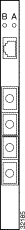
Table 6-6 describes the LEDs on the FDDI DAS interface.
| LED B | LED A | Description |
|---|---|---|
Alternately green and amber | Normal operation, indicating the B-M link is active and the A-M link is in standby mode. | |
Blinking green | Solid green | The B-M link has failed and the A-M link has taken over. The SwitchProbe device is still attached to the ring. |
Blinking green | Blinking green | Both the B-M and A-M links have failed. The SwitchProbe device is off the ring. Verify connectivity. |
Blinking amber | Blinking amber | Invalid topology. Verify connectivity. |
Solid amber |
| |
Off | Off | If off after the SwitchProbe unit boots, and if the Error LED on the front panel is blinking, indicates a SwitchProbe device failure. |
Two SC connectors let you connect the SwitchProbe device to the ring—using either a SC-to-MIC or a SC-to-SC 62.5/125 micron multimode fiber-optic cable.
You can either connect the SwitchProbe device directly to the ring as a DAS, or use a concentrator to connect it in a dual homing configuration. In either case, the SwitchProbe device sees the same network traffic.
If you connect the FDDI DAS SwitchProbe device directly to the ring as a DAS, you should use an optical bypass switch to maintain the integrity of the dual ring in the event of a failure. You can use an optical bypass switch with a modular RJ-12 station connector. For the pin designations of an RJ-12 connector, see "Cable Pinouts."
 | Caution To prevent possible damage to the SwitchProbe unit, do not insert telecommunications cabling into the optical bypass switch connector. |
To connect the FDDI DAS SwitchProbe device in a dual-homing configuration, use the two free M-ports on the concentrator, and follow these steps:
Step 1 Connect the B port of the SwitchProbe device to one of the M ports on the concentrator.
Step 2 Connect the A port of the SwitchProbe device to an M port on the same or a different concentrator.
Figure 6-16 shows the LEDs on the FDDI SAS interface.

Table 6-7 describes the PHY LEDs on the FDDI SAS interface.
| LED Color | Status | Description |
|---|---|---|
On | PHY connection is complete. This occurs after the device boots and the cable is attached. | |
| Blinking | PHY connection is in progress or no cable is attached. |
On | Broken port or failure of a Link Confidence Test (LCT). Retry the loop. If the LED is amber before the system boots, a self-test failure has occurred. | |
| Blinking | Invalid topology. |
| Off | Port is disabled because of management or controller failure. |
Each FDDI SAS SwitchProbe device is shipped with an SC-to-MIC multimode
62.5/125 micron fiber-optic cable.
To connect this device to the network, follow these steps:
Step 1 Connect the MIC connector into the FDDI ring through a concentrator.
Step 2 Connect the SC connector into the SwitchProbe FDDI SAS interface.
Cisco FDDI SwitchProbe devices are designed to operate in active mode where the device participates in all MAC protocols (Beacon and Claim Process) and SMT protocols (such as SMT neighbor information protocols).
The FDDI SAS SwitchProbe devices can also operate in MAC-passive mode. To do so, you must connect a fiber-optic splitter tap to the FDDI SAS interface. In MAC-passive mode, the device does not participate in MAC or SMT protocols and does not transmit frames.
To change the SwitchProbe device from active to MAC-passive mode, or from MAC-passive to active mode, follow these steps:
Step 1 From the Agent Configuration Utility main menu, enter 11 and press Enter.
Step 2 To change the device to either modes do one of the following:
Step 3 To return to the Agent Configuration Utility main menu, enter quit and press Enter
The Agent Configuration Utility main menu is displayed again. New values do not take effect until you reset the SwitchProbe agent. To do so, see "Configuring SwitchProbe Devices."
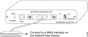
WAN interfaces support connections to V.35, X.21, EIA/TIA-449, and EIA-530.
Each WAN interface is a single port with a 26-pin, D-type connector. Use an appropriate adapter cable and WAN tap for each supported connection. The WAN interface operates in monitor mode only (tracking network traffic).
Before connecting the SwitchProbe device to the network, note the following warnings:
| Warning This equipment is to be installed and maintained by service personnel only as defined by AS/NZS 3260 Clause 1.2.14.3 Service Personnel. |
| Warning The telecommunications lines must be disconnected 1) before unplugging the main power connector and/or 2) while the housing is open. |
| Warning Do not work on the system or connect or disconnect cables during periods of lightning activity. |
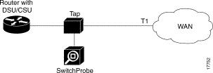
You use a WAN tap kit to connect the WAN interface to a network segment.
The WAN tap monitors the DTE and DCE circuits of a link between a router and a channel service unit/data service unit (CSU/DSU). You can connect and disconnect the SwitchProbe device without disrupting the link between the router and the CSU/DSU.
The WAN tap kit consists of the following items:
To install the WAN tap kit, see Figure 6-17 and follow these steps:
Step 1 Insert the one-foot section of the Y-shaped cable between the router and the CSU/DSU.
This section of the Y-shaped tap cable has identical connectors on each end. (Connector styles include V.35, X.21, EIA/TIA-232, EIA/TIA-449, and EIA-530.)
 | Caution Never use force to connect the cables. Forcing connectors can permanently damage the connector pins. |
Step 2 Insert the six-inch section of the Y-shaped cable into the tap unit.
This section of the Y-shaped tap cable contains a DB-26 connector.
Step 3 Insert one end of the 15-foot, straight tap cable into the tap unit.
Step 4 Insert the other end into the WAN port on the SwitchProbe device.
This cable has two DB-26 connectors (one at each end).
Step 5 Power on the device.
The POWER LED on the tap unit lights up and remains on while the tap unit receives power.
You can connect a management device to the Multiport T1/E1 WAN SwitchProbe device in one of two ways:
The Multiport T1/E1 WAN SwitchProbe device supports out-of-band management through the serial port labeled Remote using SLIP, or through the Ethernet or Token Ring interface.
Use the SLIP connection as a secondary connection to access all network statistics. The SLIP link is normally used as a backup link when the network is not operational, or when the agent is not accessible.
To perform out-of-band management through the active Ethernet interface, follow these steps:
Step 1 Connect an Ethernet cable to the Ethernet interface.
Step 2 Configure the interface mode to manage.
Set the speed of the Token Ring interface to match the speed of the network before you connect the SwitchProbe device, or it might interfere with network operations.
To perform out-of-band management through the active Token Ring interface, follow these steps:
Step 1 Connect a Token Ring cable to the Token Ring interface.
Step 2 Configure the interface mode to manage.
The Multiport T1/E1 WAN SwitchProbe device supports side-band management (manage and monitor mode on the same interface) through the active Ethernet interface, or through the active Token Ring interface.
To make a side-band connection, follow these steps:
Step 1 Connect an Ethernet cable to the active Ethernet interface, or connect a Token Ring cable to the active Token Ring interface.
Step 2 Configure the interface mode to manage and monitor.
Each WAN interface is a single port with a 26-pin, D-type connector. You use a T1/E1 WAN tap (included with the SwitchProbe device) to connect the WAN interface to the network segment.
The Channelized T1/E1 WAN and Multiport T1/D or E1/D WAN SwitchProbe device is shipped with a T1/E1 WAN tap kit, that consists of the following items:
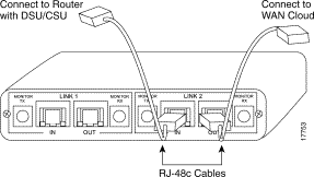
Figure 6-18 shows the front panel of the T1/E1 WAN tap. The front panel of the tap contains one DB-25 port.
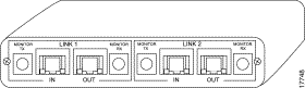
Figure 6-19 shows the rear panel of the T1/E1 WAN tap. The rear panel contains four RJ-48c ports—labeled IN and OUT; and four Bantam ports—labeled Monitor TX and Monitor RX.
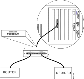
Connecting a T1 or E1 network segment to a T1 or E1 WAN interface on a Channelized WAN or a T1/D or E1/D WAN SwitchProbe device is a two-stage process:
To connect a T1/E1 WAN tap to the SwitchProbe device, see Figure 6-20 and follow these steps:
Step 1 Connect the DB-25F (female) end of the 15-foot cable (included with the SwitchProbe device) to the 25-pin male connection on the front of the tap.
Step 2 Connect the DB-26M (male) end of the 15-foot cable to one of the SwitchProbe device WAN interfaces (26-pin female connector).
Step 3 To monitor a T1 line, set the DIP switch (on the right front of the tap) to T1.
To monitor an E1 line, set the DIP switch to E1.
Step 4 To monitor RJ-48c or BNC connections, set the DIP switch (on the right front of the tap) to RJ
To monitor Bantam connections, set the DIP switch to Bantam.
Because routers have many different types of connectors, there are many ways you can connect a tap to a network segment.
The following sections describe common scenarios for connecting the T1/E1 WAN tap to a network segment:
Figure 6-21 shows how to place the tap and SwitchProbe device between a router with Data Service Unit (DSU) and a Channel Service Unit (CSU) connected to a WAN cloud.
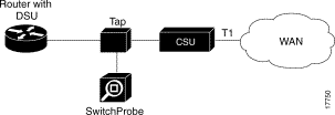
The T1/E1 WAN tap kit consists of two RJ-48c cables (among other cables). To connect the tap to a router (with DSU) and a CSU, see Figure 6-22 and follow these steps:
Step 1 Connect one end of the RJ-48c cable to the tap port labeled IN.
Step 2 Connect the other end of the RJ-48c cable to the router (with DSU).
Step 3 Connect one end of the second RJ-48c cable to the tap port labeled OUT.
Step 4 Connect the other end of the second RJ-48c cable to the CSU.
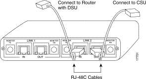
Figure 6-23 shows how to place the tap and SwitchProbe device between a router (with DSU/CSU) and a T1 line connected to a WAN cloud.
The T1/E1 WAN tap kit consists of two RJ-48c cables (among other cables). To connect the tap to a router (with DSU/CSU) and a WAN cloud, see Figure 6-24 and follow these steps:
Step 1 Connect one end of the RJ-48c cable to the tap port labeled IN.
Step 2 Connect the other end of the RJ-48c cable to the router (with DSU/CSU).
Step 3 Connect one end of the second RJ-48c cable to the tap port labeled OUT.
Step 4 Connect the other end of the second RJ-48c cable to the WAN cloud.
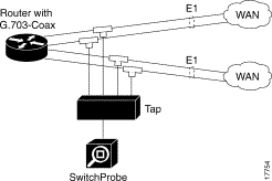
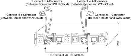
Figure 6-25 shows how to place the tap and SwitchProbe device between a router (with G.703-coax) and an E1 line connected to a WAN cloud.
The T1/E1 WAN tap kit consists of two RJ-48c-to-dual-BNC cables (among other cables). To connect the tap to a router (with G.703-coax) and a WAN cloud, see Figure 6-26 and follow these steps:
Step 1 Connect the end of the cable with RJ-48c connector to the tap port
labeled IN.
Step 2 Connect the other end of the RJ-48c cable (with dual BNC connectors) to a T-connector (between router and WAN cloud).
Step 3 Connect the end of the second cable (with RJ-48c connector) to the tap port labeled OUT.
Step 4 Connect the other end of the second RJ-48c cable (with dual BNC connectors) to the T-connector (between router and WAN cloud).
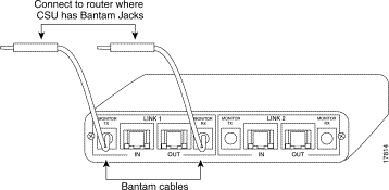
Figure 6-27 shows how to place the tap and SwitchProbe device between a router (where the CSU has Bantam jacks) and a T1/E1 line connected to a WAN cloud.
The T1/E1 WAN tap kit consists of Bantam jack cables (among other cables). To connect the tap to a router (where the CSU has Bantam jacks) and a WAN cloud, see Figure 6-28 and follow these steps:
Step 1 Connect the end of the cable (without Bantam jacks) to the tap port
labeled IN.
Step 2 Connect the other end of this cable (with Bantam jacks) to the router (with CSU having Bantam jacks).
Step 3 Connect the end of the second cable (without Bantam jacks) to the tap port labeled OUT.
Step 4 Connect the other end of this cable (with Bantam jacks) to the router (where the CSU has Bantam jacks).
Depending on the CSU model, not all Bantam-to-Bantam connections are successful. As an alternate, use the tap-to-router cabling method, using an RJ-48-to-Bantam cable (Figure 6-29).
The T1/E1 WAN tap kit consists of RJ-48-to-Bantam jack cables (among other cables). To connect the tap to a router (where the CSU has Bantam jacks) and a WAN cloud, see Figure 6-29 and follow these steps:
Step 1 Set the DIP switch (on the right front of the tap) to RJ.
Step 2 Connect the end of the cable (with RJ-48 connector) to the tap port
labeled IN.
Step 3 Connect the other end of this cable (with Bantam jacks) to the router (where the CSU has Bantam jacks).

HSSI SwitchProbe devices use a HSSI tap to connect to the DTE and DCE circuits of the WAN link.
The HSSI tap measures 1.5 inches high, by 4 inches wide, by 4 inches deep, and can be set on a tabletop. The front panel of the tap includes a single DB-26 connector to connect the tap module to the WAN port of the SwitchProbe device.
A single LED, labeled Interlock, indicates that the corresponding port has a good link status signal. If the LED is off, it indicates that there is no cable connected or there is a problem with the corresponding HSSI port on the SwitchProbe device.
The rear panel includes two SCSI II connectors:
The HSSI SwitchProbe device taps the DTE and DCE circuits of the HSSI link through an active tap interface. Connecting the HSSI SwitchProbe device to the network segment is a two-step process:
Step 1 Connect the HSSI tap between the router and CSU/DSU.
Step 2 Connect the HSSI interface of the SwitchProbe device to the tap.
Before connecting the HSSI SwitchProbe device to the network segment, you must follow these prerequisite steps:
Step 1 Set the WAN interface speed if the speed of the network to which you are connecting is not 1250 kbps. See "Changing the Token Ring and WAN Interface Speed," in "Initializing a SwitchProbe Device."
Step 2 Set the encapsulation protocol, if the encapsulation protocol used on the network to which you are connecting is not Cisco HDLC. See "Changing the Encapsulation Protocol (WAN Only)" in "Initializing a SwitchProbe Device."
To connect the HSSI SwitchProbe device to the network using the HSSI tap, see Figure 6-30, and follow these steps:
Step 1 Use the cable that connects the router to the DSU/CSU to connect the router to the HSSI IN port on the HSSI tap.
Step 2 Use the HSSI cable (included with the SwitchProbe device) to connect the DSU/CSU to the HSSI OUT port on the HSSI tap.
Step 3 Use the tap cable (included with the SwitchProbe device) to connect the single DB-26 port on the back of the HSSI tap to the HSSI WAN interface on the SwitchProbe device.
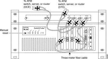
The OC-3 ATM interface supports OC-3 multimode fiber cable only. The physical ATM interface consists of two interfaces—one for a DTE connection, and one for a DCE connection. Each ATM interface contains an SC connector and three LEDs. The ATM interface operates in monitor mode only.
OC-3 ATM SwitchProbe device requires a fiber-optic splitter, shipped with the device, to monitor the network. The splitter is passive—link integrity is maintained whether the device is on or off.
The fiber-optic splitter (Figure 6-31) contains three female SC-duplex connection ports labeled A, B, and Probe.
For instructions on installing the fiber-optic splitter, see "Attaching the Splitter Tap Rack Panel (Optional)" and "Installing a Splitter Tap in a Rack Panel (Optional)" in "Installing a SwitchProbe Device."
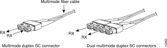
Two 24-foot SC-duplex-to-SC-duplex multimode fiber cables (Figure 6-32) are shipped with the OC-3 ATM SwitchProbe device.
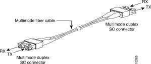
One four-foot SC-duplex-to-dual-SC-duplex multimode fiber cable (Figure 6-33) is also shipped with the ATM SwitchProbe device.
To connect the fiber-optic splitter tap to the network, see Figure 6-34 and follow
these steps:
Step 1 Remove all dust caps from the fiber-optic splitter tap connector ports.
Step 2 Remove all dust caps from connectors at the ends of the cables you will be using.
Step 3 Make sure that a multimode fiber cable with SC male connectors is connected to an ATM switch, server, or router.
Step 4 Connect the other end of the multimode fiber cable with SC male connectors to the splitter tap female SC duplex connector labeled A.
Step 5 Connect one end of the 24-foot, fiber cable (with male SC connectors) that came with the ATM SwitchProbe device to a second ATM switch, server, or router.
Step 6 Connect the other end of the 24-foot, fiber cable (that came with the device) to the splitter tap female SC duplex connector labeled B.
To connect the fiber-optic splitter tap to the ATM SwitchProbe device, see Figure 6-34 and follow these steps:
Step 1 Connect the single-duplex end of the 4-foot SC duplex multimode fiber cable shipped with the SwitchProbe device to the splitter tap female SC duplex connector labeled Probe.
The other end of the three-meter SC duplex multimode fiber cable splits into two separate ends. Note that the SC connectors only contain receive (Rx) connections.
Step 2 Connect each end of the cable into the ATM interface cards of the ATM SwitchProbe device as follows:
(a) Connect the twin-duplex end of the cable labeled DCE into the ATM DCE port on the SwitchProbe device.
(b) Connect the twin-duplex end of the cable labeled DTE into the ATM DTE port on the SwitchProbe device.
You can connect a management device to the OC-3 ATM SwitchProbe device in one of two ways:
The OC-3 ATM SwitchProbe device supports out-of-band management through the serial port labeled Remote using SLIP or through the Ethernet interface.
You can use the SLIP connection as a secondary connection through which you access all network statistics. The SLIP link is normally used as a backup link when the network is not operational or when the agent is not accessible.
To perform out-of-band management through the active Ethernet interface, follow these steps:
Step 1 Connect an Ethernet cable to the active Ethernet interface.
Step 2 Configure the interface mode to manage.
The OC-3 ATM SwitchProbe device supports side-band management (manage and monitor mode on the same interface) through the active Ethernet interface of the device.
To make a side-band connection, follow these steps:
Step 1 Connect an Ethernet cable to the active Ethernet interface on the front panel.
Step 2 Configure the interface mode to manage and monitor.
Table 6-8 describes the LEDs on the OC-3 ATM interface.
| LED Position | LED Color | Status | Meaning |
|---|---|---|---|
Amber | On | Heavy network traffic. | |
Blinking | Moderate network traffic. | ||
Off | No network traffic. | ||
Middle | Amber | Off (always) | No transmit activity. |
Green | On | Link signal has been detected. | |
Off | No link signal has been detected or no cable is attached. |
Figure 6-35 shows the LEDs on the OC-3 ATM interface.

Connecting a DS-3 ATM interface to a full-duplex network segment is a two-step process:
Step 1 Connect the DS-3 ATM tap to the DS-3 ATM interface on the SwitchProbe device
Step 2 Connect two DS-3 ATM devices to the DS-3 ATM tap (to accumulate statistics about data as it travels on the network segment)
Figure 6-36 shows the front panel of the DS-3 ATM tap with BNC connectors.

Figure 6-37 shows the rear panel of the DS-3 ATM tap with a female DB-15 connector.
To connect the DS-3 ATM tap to the DS-3 ATM SwitchProbe device, see Figure 6-38 and follow these steps:
Step 1 Locate the 15-foot cable (with a male DB-15 connector at one end and a female DB-15 connector at the other end) that is shipped with the tap.
Step 2 Plug the female connector of this cable into port 1 on the DS-3 ATM interface (port 1 is the ATM port).
Step 3 Plug the other end of the 15-foot cable (the end with the male DB-15 connector) into the female DB-15 port of the DS-3 ATM tap.
To connect the DS-3 ATM tap to the network, see Figure 6-39 and follow these steps:
Step 1 Locate the two cables that connect one switch, server, or router to another
DS-3 ATM switch, server, or router.
Step 2 Unplug these two cables from one of the two DS-3 ATM devices.
Step 3 Plug the ends of these two cables into the two ports labeled IN on the DS-3 ATM tap.
Step 4 Locate two six-foot cables (with BNC connectors at each end) that are shipped with the SwitchProbe device.
Step 5 Plug one end of each of these cables into the two ports labeled OUT on the
DS-3 ATM tap.
Step 6 Plug the remaining connector on each of these cables into the DS-3 ATM device from which you unplugged cables in Step 2.
Step 7 See Figure 6-40 to confirm that the new cabling setup reestablished the connections you had previously.
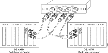
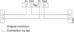
Table 6-9 shows the LEDs on the DS-3 ATM interface.
| LED Position | LED Color | Status | Meaning |
|---|---|---|---|
Green | On | Link signal has been detected. | |
|
| Off | No link signal has been detected or no cable is attached. |
Second LED | Green | Off | Not used. |
Third LED | Green | On | Link signal has been detected. |
Off | No link signal has been detected or no cable is attached. | ||
Fourth LED | Green | Off | Not used. |
Figure 6-41 shows the LEDs on the DS-3 ATM interface.

![]()
![]()
![]()
![]()
![]()
![]()
![]()
![]()
Posted: Wed Oct 2 08:18:10 PDT 2002
All contents are Copyright © 1992--2002 Cisco Systems, Inc. All rights reserved.
Important Notices and Privacy Statement.