|
|

This appendix shows the pin designations for the following:
Table C-1 describes the pin designations for the Ethernet AUI interface.
| Pin | Signal Name | Direction |
|---|---|---|
1 | Logic Ground | (GND) |
2 | Collision Input+ (CI+) | In |
3 | Transmit Data+ (DO+) | Out |
4 | Logic Ground | (GND) |
5 | Receive Data+ (DI+) | In |
6 | +12V Logic Ground | (GND) |
7 | Not used |
|
8 | Logic Ground | (GND) |
9 | Collision Input- (CI-) | In |
10 | Transmit Data- (DO-) | Out |
11 | Logic Ground | (GND) |
12 | Receive Data- (DI-) | In |
13 | +12V Power (+12) | Out |
14 | Logic Ground | (GND) |
15 | Not used |
WAN interfaces support V.35, RS-449, EIA-530, X.21 with one clock source cable pinouts, and X.21 with two clock source cable pinouts.
The cable configurations for these interfaces are shown in Figures C-1 through C-5.
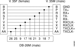
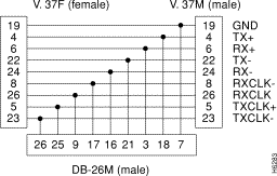
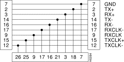
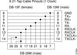
The WAN interface is an EIA/TIA-232 connector.
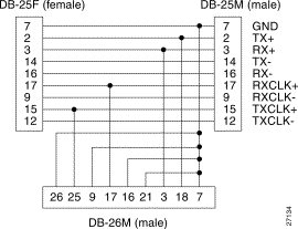
Table C-2 shows the EIA/TIA-232 pin designations for the console and remote serial ports.
Table C-3 shows the Token Ring UTP pin designations for the RJ-45 connector.
| Pin | Signal Name | IBM-Type Three-Wire Color |
|---|---|---|
1 |
|
|
2 |
|
|
3 | T - | Blue with white stripe |
4 | R + | White with orange stripe |
5 | R - | Orange with white stripe |
6 | T + | White with blue stripe |
7 |
|
|
8 |
|
Table C-4 lists the pin designation for the RJ-12 connector used to connect a FDDI SwitchProbe device to an optical bypass switch.
| Pin | Meaning |
|---|---|
1 | Relay drive: + 5.0 V DC |
2 | Relay drive: + 5.0 V DC |
3 | Bypass_enable |
4 | Bypass_enable |
5 | Bypass_present |
6 |
Table C-5 lists the RJ-45 connectors used to connect a SwitchProbe device to half-duplex 100Base TX and 100Base T4 networks.
| Pin | 100Base TX | 100Base T4 |
|---|---|---|
1 | Transmit+ | TX_D1+ |
2 | Transmit- | TX_D1- |
3 | Receive+ | RX_D2+ |
4 |
| BI_D3+ |
5 |
| BI_D3- |
6 | Receive- | RX_D2- |
7 |
| BI_D4+ |
8 |
|
Table C-6 lists the pin connections for the 6-pin mini-DIN connector used to connect the Fast Ethernet FDX tap for 100Base-FX to an optical bypass switch.
| Pin | Meaning |
|---|---|
1 | Secondary +5 V |
2 | Primary GND |
3 | Primary GND |
4 | Secondary GND |
5 | Common to 6 |
6 |
Table C-7 shows the EIA-232 pin designations for the console and remote serial ports.
| Pins | Signal | Direction |
|---|---|---|
1 | Carrier Detect (DCD) | In |
2 | Receive Data (RXD) | In |
3 | Transmit Data (TXD) | Out |
4 | Data Terminal Ready (DTR) | Out |
5 | Signal GND | (GND) |
6 | Data Set Ready (DSR) | In |
7 | Request To Send (RTS) | Out |
8 | Clear To Send (CTS) | In |
9 | Ring Indicator (RI) |
Use a null-modem cable to connect the Console port to an ASCII terminal. Figure C-7 illustrates sample wiring for the crossover cable type.

![]()
![]()
![]()
![]()
![]()
![]()
![]()
![]()
Posted: Wed Oct 2 08:03:25 PDT 2002
All contents are Copyright © 1992--2002 Cisco Systems, Inc. All rights reserved.
Important Notices and Privacy Statement.