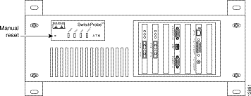
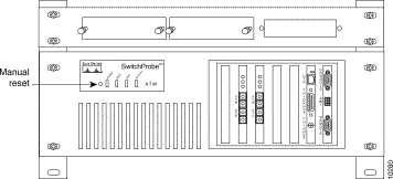
|
|

Before beginning the installation process, read the following installation cautions and warnings:
 | Warning Read the installation instructions before you connect the system to its power source. |
 | Warning Only trained and qualified personnel should be allowed to install, replace, or service this equipment. |
 | Warning Ultimate disposal of this product should be handled according to all national laws and regulations. |
 | Warning Before working on a system that has an on/off switch, turn OFF the power and unplug the power cord. |
 | Warning The safety cover is an integral part of the product. Do not operate the unit without the safety cover installed. Operating the unit without the cover in place will invalidate the safety approvals and pose a risk of fire and electrical hazards. |
 | Warning Blank faceplates and cover panels serve three important functions: they prevent exposure to hazardous voltages and currents inside the chassis; they contain electromagnetic interference (EMI) that might disrupt other equipment; and they direct the flow of cooling air through the chassis. Do not operate the system unless all cards, faceplates, front covers, and rear covers are in place. |
 | Warning Before working on equipment that is connected to power lines, remove jewelry (including rings, necklaces, and watches). Metal objects will heat up when connected to power and ground and can cause serious burns or weld the metal object to the terminals. |
 | Warning Do not work on the system or connect or disconnect cables during periods of lightning activity. |
 | Warning Hazardous network voltages are present in WAN ports regardless of whether power to the unit is OFF or ON. To avoid electric shock, use caution when working near WAN ports. When detaching cables, detach the end away from the unit first. |
 | Warning To avoid electric shock, do not connect safety extra-low voltage (SELV) circuits to telephone-network voltage (TNV) circuits. LAN ports contain SELV circuits, and WAN ports contain TNV circuits. Some LAN and WAN ports both use RJ-45 connectors. Use caution when connecting cables. |
 | Caution To prevent possible damage to the SwitchProbe device, see ""Site Requirements," before starting the installation process. |
Table 4-1 lists the basic steps for connecting your SwitchProbe device to the network.
If you are familiar with the SwitchProbe device, use this table to proceed directly to the tasks you want to perform. If you are unfamiliar with the device, read the entire chapter and use this table as a checklist to perform the required tasks to correctly install your device.
| Be Sure To... | As Described in |
|---|---|
Select a proper site. | |
Unpack and inspect the device. | |
Mount the device in an equipment rack. | |
Mount a splitter tap rack panel. | |
Connect the device to a power source. | |
Configure the device using an ASCII terminal. or Set up a BOOTP server to automatically configure the device. | |
Make the network connections. | |
Customize the device configuration. | "Configuring SwitchProbe Devices" and |
Configure interface options to customize WAN, Fast Ethernet, and ATM devices. | "Configuring Special Interface Options" in "Configuring SwitchProbe Devices" |
Add more features to the device. |
You can mount the front-access chassis in a standard 19-inch equipment rack. To do so, you must first attach mounting brackets to the device. An accessory kit that includes two mounting brackets and screws is shipped with each device.
 | Warning To prevent the device from overheating, do not operate it in an area that exceeds the maximum recommended ambient temperature of 104° F (40° C). To prevent airflow restriction, allow at least 3 inches (7.6 cm) of clearance around the ventilation openings. |
 | Warning To prevent bodily injury when mounting or servicing this unit in a rack, you must take special precautions to ensure that the system remains stable. The following guidelines are provided to ensure your safety: |
To attach mounting brackets to the device, see Figure 4-1 and follow these steps:
Step 1 Stand the device upright with the front panel facing you.
Step 2 Align the four holes of one of the mounting brackets with the four holes on the right side of the device.
Step 3 Insert four screws through the holes on the bracket and into the device.
Step 4 Tighten the screws until the mounting bracket is attached securely to the device.
Step 5 Align the four holes of the other mounting bracket with the four holes on the left side of the device.
Step 6 Insert four screws through the holes on the bracket and into the device.
Step 7 Tighten the screws until the mounting bracket is securely attached to the device.

To mount a device in a standard 19-inch equipment rack, see Figure 4-2 and follow these steps:
Step 1 Slide the device (with the front panel facing you) into the equipment rack.
Step 2 Align the holes on the attached mounting brackets with the desired holes on the front of the equipment rack.
Step 3 Insert screws (provided with the device) into the desired holes of the mounting bracket.
Step 4 Tighten each screw until the device is securely attached to the equipment rack.

The rack panel (Figure 4-3) is not shipped with the SwitchProbe device, but can be purchased from Cisco Systems. The rack panel lets you mount up to three splitter taps in a standard 19-inch equipment rack.

To attach the splitter tap rack panel to a standard 19-inch equipment rack, see Figure 4-4, and follow these steps:
Step 1 Determine the area on the equipment rack where you want to position the rack panel (either above or below the SwitchProbe device).
Step 2 Align the rack panel mounting holes with the desired holes on the equipment rack.
Step 3 Insert screws into the desired holes.
Step 4 Tighten each screw until the rack panel is secured to the equipment rack.
Figure 4-4 shows a fiber-optic splitter rack panel mounted in a standard 19-inch equipment rack, above an installed SwitchProbe device.

To install a splitter tap in a rack panel that is already attached to a standard equipment rack, see Figure 4-5 and follow these steps:
Step 1 Slide the splitter tap (with the connection ports facing you) into an open slot on the rack panel.
Step 2 Secure the splitter tap to the rack panel by pushing the two fastener buttons on the tap into their corresponding holes on the rack panel.
Depending on the SwitchProbe model you have, some devices have a single power socket and some older devices have two power sockets (labeled Power In and Power Out).
 | Caution To prevent any possible damage to the SwitchProbe device, and to ensure that it operates correctly, never use the Power Out socket found on the older models. |
 | Caution Before connecting the SwitchProbe device to the network, see "Site Requirements." |
Each device is equipped with an AC power cord for connection to an appropriate power source.
To connect a SwitchProbe device to the power source, follow these steps:
Step 1 Connect one end of the power cord to a power source.
 | Warning This equipment is intended to be grounded. Ensure that the host is connected to earth ground during normal use. |
Step 2 Connect the other end of the AC power cord to the power socket on the back of the device.
Step 3 Turn the device on.
 | Caution To avoid damaging the device, you cannot turn the power off for four seconds after you turn the power on. |
![]()
![]()
![]()
![]()
![]()
![]()
![]()
![]()
Posted: Wed Oct 2 08:19:22 PDT 2002
All contents are Copyright © 1992--2002 Cisco Systems, Inc. All rights reserved.
Important Notices and Privacy Statement.