cc/td/doc/product/rtrmgmt/ism/ism_v2r2
hometocprevnextglossaryfeedbacksearchhelp
PDF

Table Of Contents

Enabling the ISM Environment

Enabling ISM Resource Management

Enabling SNMP Management

Enabling Resource Monitor Scheduling

Viewing and Modifying ISM Users

Enabling the ISM Environment


This chapter describes how to establish global resource monitoring options for the ISM environment. Appropriate procedures are included in the following sections:

Enabling ISM Resource Management

Enabling SNMP Management

Enabling Resource Monitor Scheduling

Viewing and Modifying ISM Users


Note If you are configuring ISM for the first time, follow the procedures in Chapter 5, "Configuring ISM," in the CiscoWorks Blue Internetwork Status Monitor Installation Guide.


Enabling ISM Resource Management

To enable ISM resource management and interface monitoring, complete the following steps:
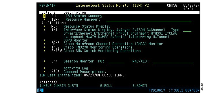

Step 1 On the ISM main menu panel ( Figure 3-1) press PF8 (ADMIN).

Figure 3-1 ISM Main Menu Panel

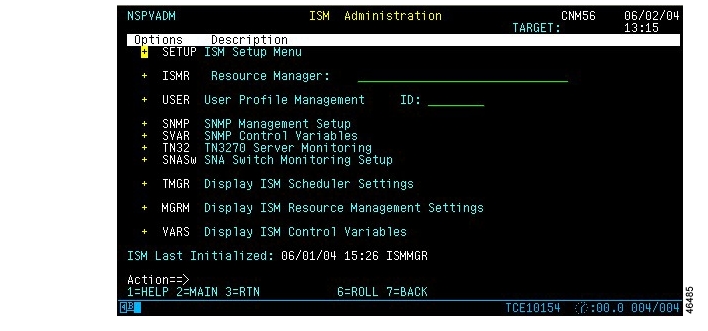
The ISM Administration menu panel ( Figure 3-2) is displayed.

Figure 3-2 ISM Administration Menu Panel

Step 2 Select Setup and press Enter. The ISM Resource Management Setup—First Panel ( Figure 3-3) is displayed.

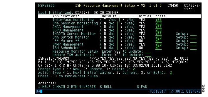
Figure 3-3 ISM Resource Management Setup—First Panel

The ISM Resource Management Setup—First Panel contains the following fields:

Field
Description

Last Initialized

Indicates the date and time the ISM Resource Manager was last initialized.

Resource Management

Indicates that resource management is enabled in the ISM interface. This field is always set to Y.

Interface Monitoring

Indicates whether interface monitoring is enabled. The display columns show the default, initial, and current values. The default setting is Y.

SNA Session Monitoring

Indicates whether SNA Session Monitoring is enabled in the ISM interface. The display columns show the default, initial, and current values. The default setting is N (not enabled).

To fully enable SNA Session Monitoring, you must create SNA Resource Management definitions.

CMCC Management

Indicates whether CMCC Management is enabled in the ISM interface. The display columns show the default, initial, and current values. The default setting is N (not enabled).

See Chapter 6, "Monitoring CMCCs," for more details.

DSPU Management

Indicates whether DSPU Monitoring is enabled in the ISM interface. The display columns show the default, initial, and current values. The default setting is N (not enabled).

To fully enable DSPU Session Monitoring, you must create DSPU Resource Management definitions.

TN3270 Server Monitor

Indicates whether the TN3270 Server Monitor is enabled in the ISM interface. The display columns show the default, initial, and current values. The default setting is N (not enabled).

To enable global TN3270 server monitoring, enter YES in the Setup field. See Chapter 8, "Monitoring TN3270 Servers," for more details.

SNA Switch Monitor

| Indicates whether the SNA Switch Monitor is enabled in the ISM interface. The display columns show the default, initial, and current values. The default setting is N (not enabled).

To enable SNA Switch monitoring, enter YES in the Setup field. See Chapter 9, "Monitoring SNA Switch Resources" for more details.

Reserved


SNMP Management

Indicates whether SNMP Management is enabled in the ISM interface. The display columns show the default, initial, and current values associated with SNMP Session options. The default setting is N (not enabled).

To enable global SNMP management, enter YES in the Setup field. See the "Enabling SNMP Management" section for more details.

ISM Scheduler

Indicates whether the ISM Scheduler is enabled in the ISM interface. The display columns show the default, initial, and current values associated with scheduling options. The default setting is N (not enabled).

To enable global scheduling, enter YES in the Setup field. See the "Enabling Resource Monitor Scheduling" section for more details.


Step 3 Press PF8 to display the ISM Resource Management Setup—Second Panel ( Figure 3-4).


Note Press PF4 to save your changes, exit this procedure, and return to the ISM Administration menu panel.


Figure 3-4 ISM Resource Management Setup—Second Panel

The ISM Resource Management Setup—Second Panel contains the following fields:

Field
Default Value

ISM Autotasks

ISM Resource MGR Autotask

Defines the default autotask, ISMMGR for the ISM Resource manager. Do not change this value.

ISM Interface MGR Autotask

ISMMGRI

ISM Refresh Operator

ISMMGRS

ISM Message Autotask

ISMMGRM

ISM Refresh Delay

20

Generic Alert Generation

To send generic alerts to NetView's NPDA hardware monitor, enable the alert generation rule for resource status.

Resource Status

No

Resource Perf/Memory

No

CMCC Perf/Memory

No

Interface Status

No

ISM Functions

ISM CMCC Recovery

No

ISM Base Timer (Scheduler)

15

ISM SMF Recording

No

If you change the ISM Recording setting to Yes, the ISM SMF Recording RECID field automatically defaults to 220.

ISM SMF Recording RECID

220

ISM Enable Override

15

ISM Enable Override setting limits the amount of time (in minutes) that an operator remains in enable mode. If the operator enters enable mode for a router, ISM cannot monitor the router. If the operator remains in enable mode for two monitoring periods, ISM Enable Override removes the operator from enable mode.


Step 4 Press PF8 to display the ISM Resource Management Setup—Third Panel ( Figure 3-5).


Note Press PF4 to save your changes, exit this procedure, and return to the ISM Administration menu panel.


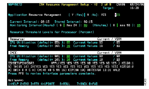
Figure 3-5 ISM Resource Management Setup—Third Panel

The ISM Resource Management Setup—Third Panel contains the following fields:

Field
Default Value

Resource Management

Indicates that resource management is enabled in the ISM interface. This field is always set to Y.

Monitoring Intervals

Current Interval

Current resource monitoring interval in hours and minutes.

Stored Interval

Stored resource monitoring interval in hours and minutes.

Monitoring Interval (Hours) and (Minutes)

Specify a new resource monitoring interval in hours and minutes.


Note Reducing ISM monitoring intervals (thereby increasing the frequency with which ISM monitors resources) can impact system performance.


Resource Thresholds

CPU Utilization

Specify a new CPU utilization threshold for a resource, as a two-digit percentage. For example, enter 80 to enter a new threshold of 80%.

Enter 00 to suspend CPU utilization threshold monitoring for a resource.

Free Memory

Specify a new free memory threshold for a resource, as a two-digit percentage. For example, enter 20 to enter a new threshold of 20%.

Enter 00 to suspend free memory monitoring for a resource.

CMCC Thresholds

CPU Utilization

Specify a new CPU utilization threshold for a CMCC resource, as a two-digit percentage. For example, enter 80 to enter a new threshold of 80%.

Enter 00 to suspend CPU utilization threshold monitoring for a CMCC resource.

Free Memory

Specify a new free memory threshold for a CMCC resource, as a two-digit percentage. For example, enter 20 to enter a new threshold of 20%.

Enter 00 to suspend free memory threshold monitoring for a CMCC resource.


Step 5 Press PF8 to display the ISM Resource Management Setup—Fourth Panel ( Figure 3-6).


Note Press PF4 to save your changes, exit this procedure, and return to the ISM Administration menu panel.


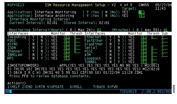
Figure 3-6 ISM Resource Management Setup—Fourth Panel

The ISM Resource Management Setup—Fourth Panel contains the following fields:

Field
Default Value

Interface Monitoring

Enables or disables interface monitoring for all resources.

Interface Archiving

Enables or disables interface archiving for all resources.

Monitoring Intervals

Current Interval

Current interface monitoring interval in hours and minutes.

Stored Interval

Stored interface monitoring interval in hours and minutes.

Monitoring Interval (Hours) and (Minutes)

Specify a new interface monitoring interval in hours and minutes.


Note Reducing ISM monitoring intervals (thereby increasing the frequency with which ISM monitors interfaces) can impact system performance.


Interfaces

TokenRing

Indicates whether Token Ring interfaces are to be monitored. The default setting is YES (monitor Token Ring interfaces).

Ethernet

Indicates whether Ethernet interfaces are to be monitored. The default setting is YES (monitor Ethernet interfaces).

FDDI

Indicates whether FDDI interfaces are to be monitored. The default setting is YES (monitor FDDI interfaces).

ASYNC

Indicates whether Asynchronous interfaces are to be monitored. The default setting is NO (do not monitor Asynchronous interfaces).

HSSI

Indicates whether HSSI interfaces are to be monitored. The default setting is NO (do not monitor HSSI interfaces).

Tunnel

Indicates whether Tunnel interfaces are to be monitored. The default setting is NO (do not monitor Tunnel interfaces).

IBMCLAW

Indicates whether IBM CLAW interfaces are to be monitored. The default setting is NO (do not monitor IBM CLAW interfaces).

FastEther

Indicates whether Fast Ethernet interfaces are to be monitored. The default setting is YES (monitor Fast Ethernet interfaces).

Serial

Indicates whether Serial interfaces are to be monitored. The default setting is YES (monitor Serial interfaces).

Loopback

Indicates whether Loopback interfaces are to be monitored. The default setting is NO (do not monitor Loopback interfaces).

Channel

Indicates whether Channel interfaces are to be monitored. The default setting is YES (monitor Channel interfaces).

ISDN

Indicates whether ISDN interfaces are to be monitored. The default setting is NO (do not monitor ISDN interfaces).

ATM

Indicates whether ATM interfaces are to be monitored. The default setting is NO (do not monitor ATM interfaces).

MPC

Indicates whether Multiprotocol (MPC) Point-to-Point interfaces are to be monitored. The default setting is NO (do not monitor MPC interfaces).

GigaEther

Indicates whether Gigabit Ethernet interfaces are to be monitored. The default setting is NO (do not monitor Gigabit Ethernet interfaces).

Thresh

Indicates the interface reliability threshold for each type of interface. If the reliability as reported by the IOS "show interface" command is less than or equal to the specified value, a message is written to the NetView log. A value of "0" disables reliability monitoring. This only applied to router interfaces. The value specified for Ethernet also applies to FastEthernet and GigabitEthernet.

Sub

Indicates whether subinterfaces should be monitored for each type of interface.


Step 6 Press PF8 to display the Resource Management Constants Setup panel ( Figure 3-7).


Note Press PF4 to save your changes, exit this procedure, and return to the ISM Administration menu panel.


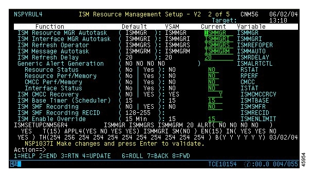
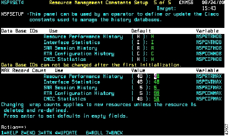
Figure 3-7 ISM Resource Management Constants Setup—Fifth Panel

The Resource Management Constants Setup panel contains the following fields:

Field
Default Value

Data Base IDs


Note You can change the VSAM database IDs that ISM uses for global resource management data only after ISM has been installed, and before ISM has been initialized for the first time.


Resource Performance History

VSAM database ID used by ISM for global resource performance history data.

Interface Statistics

VSAM database ID used by ISM for global interface statistics.

SNA Session History

VSAM database ID used by ISM for global SNA session history data.

AIX Configuration History

VSAM database ID used by ISM for global AIX Configuration history data.

CMCC Statistics

VSAM database ID used by ISM for global CMCC statistics data.

MAX Record Count


Note Wrap counts are set for all resources and interfaces. If you change these values after initializing ISM, the new values apply to new resources and interfaces defined to ISM. To apply the new values to existing resources, reset the history for an individual resource or interface.


Resource Performance History

Maximum number of records the database can contain before overwriting router performance history data.

Interface Statistics

Maximum number of records the database can contain before overwriting interface statistics.

SNA Session History

Maximum number of records the database can contain before overwriting SNA session history data.

RTR Configuration History

Maximum number of records the database can contain before overwriting router configuration history data.

CMCC Statistics

Maximum number of records the database can contain before overwriting CMCC statistics.


Step 7 Press PF4 to save your changes, exit this procedure, and return to the ISM Administration menu panel.


Enabling SNMP Management

To enable SNMP Management, use one of the following procedures:

To access the SNMP Management Setup for ISM from the ISM Resource Management Setup panel, on the update option beside the SNMP Management field, type YES and press Enter. The SNMP Management Setup for ISM panel ( Figure 3-8) is displayed.

To access the SNMP Management Setup for ISM Panel from the ISM Administration panel, select SNMP and press Enter. The SNMP Management Setup for ISM panel is displayed.

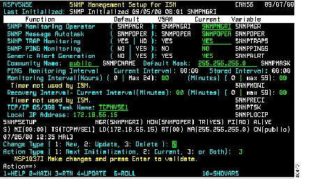
Figure 3-8 SNMP Management Setup for ISM Panel

The SNMP Management Setup for ISM panel contains the following fields:

Function
Default
Description

SNMP Monitoring Operator

SNMPMGR

Main SNMP autotask. It initializes and monitors SNMP.

SNMP Message autotask

SNMPOPER

Monitors SNMP related messages, processes SNMP traps, and performs recovery for the SNMP interface.

SNMP TRAP Monitoring

YES

Not Required.

SNMP PING Monitoring

NO

Not Required.

Generic Alert Generation

NO

Not Required.

Community Name

public

Default community name used by the SNMP manager when adding a new resource to ISM.

Default Mask

255.255.255.0

Default mask used by the SNMP manager when adding a new resource to ISM.

PING Monitoring Interval

00:00

Reserved.

Recovery Interval

00:00

Reserved.

TCP/IP OS/390 Task Name


Enter the TCP/IP task name with which to interface with NetView. This name is used to verify that TCP/IP is running.

Local IP Address


Enter the IP address of the TCP/IP with which to interface with NetView. The SNMP manager autotask uses this IP address to verify a working SNMP connection between TCP/IP and NetView.


Enabling Resource Monitor Scheduling

Consider the following guidelines when using the ISM Scheduler to enable resource monitoring intervals:

If you use the ISM Scheduler to enable resource monitoring intervals, enter every resource group you monitor on the ISM Schedule Setup panel ( Figure 3-9). ISM does not monitor resource groups that are not entered in the ISM Schedule Setup panel.

If you have not assigned some resources to a group, you can specify None as a default group ID, with a monitoring interval. Any resource not assigned to a group will be monitored according to the interval that you specified for the None group ID.

If a resource is assigned to more than one group, the monitoring interval is used according to the interval specified for the first group to which the resource is assigned.

To enable the ISM Scheduler, complete the following steps:


Step 1 On the ISM Resource Management Setup—First Panel ( Figure 3-3), beside the ISM Scheduler Setup option, enter Y, and press Enter. The ISM Schedule Setup panel ( Figure 3-9) is displayed.

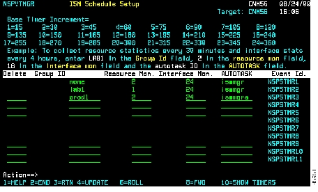
Figure 3-9 ISM Schedule Setup Panel


Step 2 On the ISM Schedule Setup panel, under the Group ID column, type the name of a resource group.

Step 3 A monitoring interval is the time that an assigned autotask waits before collecting resource and interface statistics for a selected resource group.

To specify monitoring intervals, enter the number of 15-minute increments in the Resource Mon. and Interface Mon. fields. For example, to specify an interval of 60 minutes, enter 4.

Step 4 To assign an autotask to a resource group in the AUTOTASK field, enter the name of the ISM autotask member that you want to use to manage the corresponding group of resources.

To remove an autotask monitoring schedule, enter D in the Delete field beside the resource group ID.

Step 5 Press PF4 to save your changes.


Viewing and Modifying ISM Users

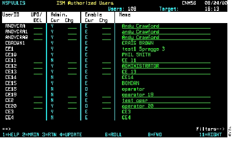
The ISM User List utility enables you to view and modify the profiles of all the users defined to ISM. The ISM user list includes the name of each user (if specified in the profile), the user ID, and the ISM user authority level.

To view a list of all the users defined to ISM, issue the ismusers command. The ISM Authorized Users panel is displayed ( Figure 3-10). To modify a users profile, change the profile options and press PF4 to update.

Figure 3-10 ISM Authorized Users Panel

For more information on defining ISM user profiles, see Chapter 5, "Configuring ISM," in the CiscoWorks Blue Internetwork Status Monitor Installation Guide.


hometocprevnextglossaryfeedbacksearchhelp

Posted: Wed Oct 13 00:42:12 PDT 2004
All contents are Copyright © 1992--2004 Cisco Systems, Inc. All rights reserved.
Important Notices and Privacy Statement.