|
|

Table Of Contents
Enabling Global Monitoring Options for All Resources
Enabling Resource Monitoring Intervals
Modifying CPU and Memory Thresholds
Enabling Resource Interface Archiving
Enabling Resource Alert Generation
Enabling Monitoring Options for Multiple Routers
Enabling Monitoring Options for Individual Resources
Disabling Archiving of Resource History and Performance Data
Deleting History and Performance Records
Changing the Database IDs and Maximum Record Counts
Creating SNA Resource Management Definitions
Adding an SNA Resource Management Definition
Displaying SNA Interface Status
Displaying SNA Interface Details
Enabling SNA Session Monitoring
Creating SNMP Resource Management Definitions
Adding SNMP Resource Definitions
Creating an SNMP Resource Control Block
Updating the Status in the Control Block
Renaming an SNMP Resource Definition
Enabling SNMP Session Monitoring
Monitoring Resources Using the Standard Interface
Displaying Resource Status Using the Standard Interface
Diagnosing Problems Using the Standard Interface
Filtering Resources Using the Standard Interface
Refreshing and Resetting Resources Using the Standard Interface
Viewing Resource Management Information Using the Standard Interface
Monitoring Resource Performance Using the Standard Interface
Viewing Hardware Alerts and Events Using the Standard Interface
Using the Standard Interface for Logging In to Routers and Issuing Commands
Using the Web Interface to Monitor Resources
Displaying Resource Status Using the Web Interface
Issuing Router Commands Using the Web Interface (SNA Only)
Showing the System (SNMP Only)
Displaying Protocol Status Using the Web Interface (SNA and SNMP)
Displaying Resource Variables Using the Web Interface (SNA and SNMP)
Viewing SNA Resource Status from VTAM Using the Web Interface (SNA Only)
Viewing Archived Configurations Using the Web Interface (SNA Only)
Viewing Router Performance History Using the Web Interface (SNA and SNMP)
Issuing Router Show Commands Using the Web Interface (SNA Only)
Displaying Interfaces Status (SNA and SNMP)
Displaying CMCC Status (SNA Only)
Monitoring ISM Resources
With ISM, you can quickly diagnose network problems, enable performance thresholds and monitoring intervals, and assign resources to management groups.
As you enable ISM monitoring resources, keep the following considerations in mind:
•
The options on the ISM Resource Management Setup panels apply to all resources managed by ISM.
•
•
•
•
To monitor ISM network resource status, complete the tasks in the following sections:
•
•
•
•
•
•
•
Enabling Global Monitoring Options for All Resources
Use the following procedures to perform global resource management:
•
•
•
•
Enabling Resource Monitoring Intervals
The Monitoring Interval field on the ISM Resource Management Setup—Third Panel ( Figure 4-5) controls the time that an ISM monitoring autotask waits before contacting resources, collecting statistics, or updating status. The default monitoring interval is 15 minutes.
Use the following procedure to enable resource monitoring intervals:
Step 1
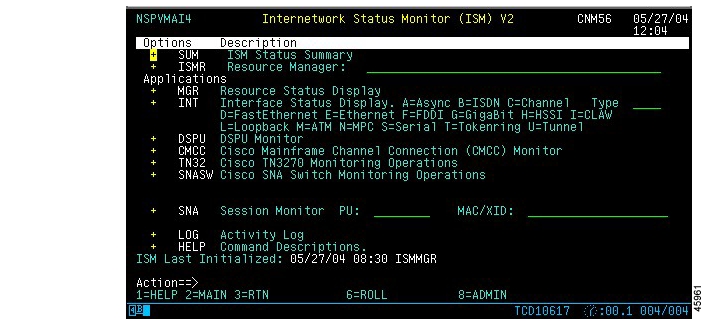
Figure 4-1 ISM Main Menu Panel
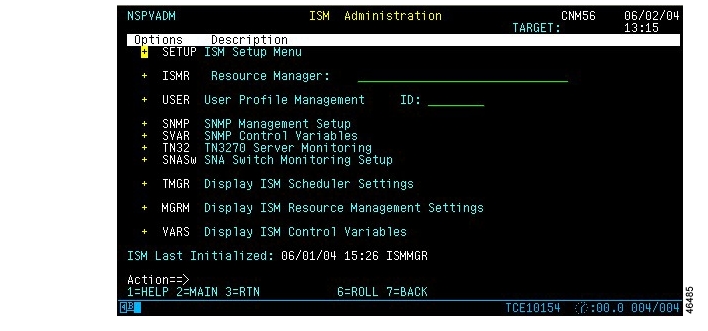
The ISM Administration menu panel ( Figure 4-2) is displayed.
Figure 4-2 ISM Administration Menu Panel
Step 2
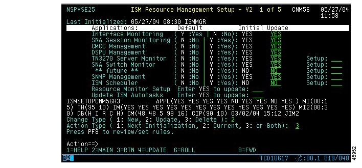
Figure 4-3 ISM Resource Management Setup—First Panel
Step 3
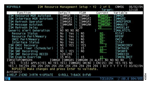
Figure 4-4 ISM Resource Management Setup—Second Panel
Step 4
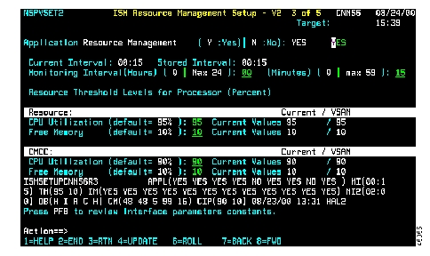
Figure 4-5 ISM Resource Management Setup—Third Panel
Use this panel to change the monitoring interval for all resources.
Use the ISM Scheduler to balance the monitoring load among a large number of resources. You can assign resources and monitoring intervals to resource groups. For more information about using the ISM Scheduler, see the "Enabling Resource Monitor Scheduling" section on page 3-16.
Modifying CPU and Memory Thresholds
You can modify CPU and memory thresholds that ISM uses for monitoring resources to issue alerts for CPU and memory performance conditions on a global or individual resource basis. The default threshold settings are 95 percent for CPU utilization and 10 percent free memory.
Use the following procedure to modify CPU and memory thresholds:
Step 1
•
•
Step 2
Step 3
If threshold settings are specified, it means that ISM indicates a performance alert (status is PERF) for the resource when the following conditions occur:
•
•
Note
To override the CPU and memory thresholds that are enabled for an individual resource, use the ISM Resource Administration panel ( Figure 4-11).
Enabling Resource Interface Archiving
If the Interface Monitoring application has been enabled in ISM, you can enable or disable interface archiving for individual resources in ISM. By default, the Interface Monitoring application is enabled by ISM and interface archiving is enabled for all resources.
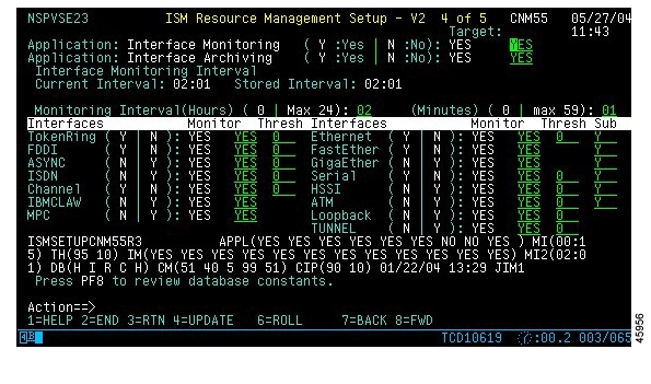
To enable or disable interface archiving for all resources, use the ISM Resource Management Setup—Fourth Panel ( Figure 4-6). Enter Y or N in the Interface Archiving option.
Figure 4-6 ISM Resource Management Setup—Fourth Panel
To override the CPU and memory thresholds that are enabled for an individual resource, use the ISM Resource Administration panel ( Figure 4-11).
Enabling Resource Alert Generation
Use the following procedure to enable resource alert generation:
Step 1
Step 2
Step 3
Step 4
Step 5
Step 6
Step 7
Step 8
Step 9
Enabling Monitoring Options for Multiple Routers
To manage large numbers of resources or to sort resources into meaningful groups, such as by location, you can assign group names to be associated with each resource. These groups can be used to filter views when monitoring resource status and to manage ISM's monitoring load by scheduling different monitoring intervals for resource groups in the ISM Scheduler application.
If you assign a resource to more than one group and also enable the ISM Scheduler application, ISM monitors the resource according to the monitoring interval associated with the first group to which the resource is assigned. The order in which you specify a group ID for a resource affects the implementation of group scheduling.
To assign a single resource to a group, on the ISM Resource Administration panel ( Figure 4-11), enter up to three group names in the Group(s) fields.
To remove a resource from any of its assigned groups, you must first remove the resource from all groups by specifying None in the first Group(s) field. You can reassign a resource to a group after is is removed from all groups.
Use the following procedure to enable monitoring options for multiple routers:
Step 1
Step 2
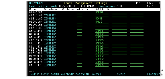
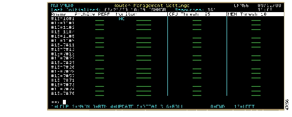
Figure 4-7 Router Management Settings Panel—1 of 2
Figure 4-8 Router Management Settings Panel—2 of 2
Step 3
Enabling Monitoring Options for Individual Resources
Use the following procedure to enable monitoring for an individual resource:
Step 1
Figure 4-9 Resource Status Panel
Step 2
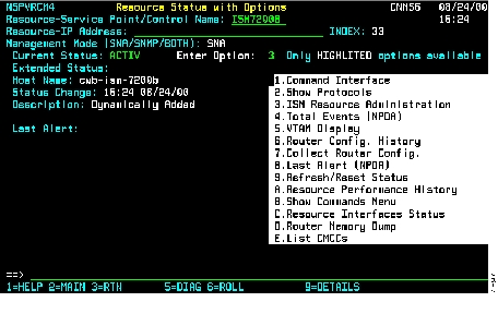
Figure 4-10 Resource Status with Options Panel
Step 3
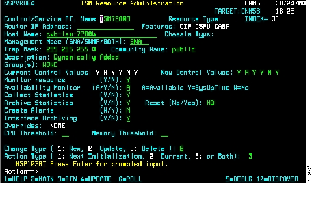
Figure 4-11 ISM Resource Administration—SNA Router
Step 4
Step 5
Step 6
Step 7
Managing Resource Data
This section includes information on the following topics:
•
•
•
Disabling Archiving of Resource History and Performance Data
By default, ISM enables resource monitoring and archiving of history and performance data, such as CPU and memory utilization statistics. To disable archiving for a single resource, on the ISM Resource Administration panel ( Figure 4-11), enter No in the Archive Statistics field.
Deleting History and Performance Records
You can remove the history and performance records for an individual resource from the history database using the Reset option on the ISM Resource Administration panel ( Figure 4-11). When you enable the Reset option, the history records are removed from the database when you press PF4 to update.
To delete history and performance records for an individual resource, on the ISM Resource Administration panel ( Figure 4-11), enter Yes in the Reset field and press PF4.
Changing the Database IDs and Maximum Record Counts
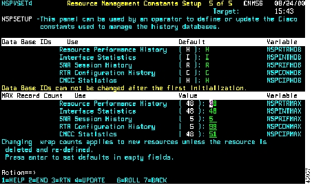
You can change the VSAM database IDs that ISM uses for global resource management data only after ISM has been installed, and before ISM has been initialized for the first time. Change the database IDs using the Resource Management Constants Setup panel ( Figure 4-12).
Figure 4-12 Resource Management Constants Setup Panel
You can also change the maximum number of records that the database contains before overwriting the data contents. The wrap counts are set for all resources and interfaces. When these values are changed after initializing ISM, the new values apply to new resources and interfaces defined to ISM. You can apply the new values to existing resources if you reset the history for an individual resource or interface. After you reset the history records, the next time the file is initialized the new values are used.
Another method of applying changed wrap counts to previously defined resources and interfaces is to delete the resource definition and redefine the resource to ISM.
Creating SNA Resource Management Definitions
To create SNA resource management definitions, complete the tasks in the following sections:
•
•
•
•
Note
Adding an SNA Resource Management Definition
To add SNA resource management definitions, complete the following steps:
Step 1
Figure 4-13 Resource Status with Options Panel
Step 2
Resource Service Point/Control NameManagement ModeStep 3
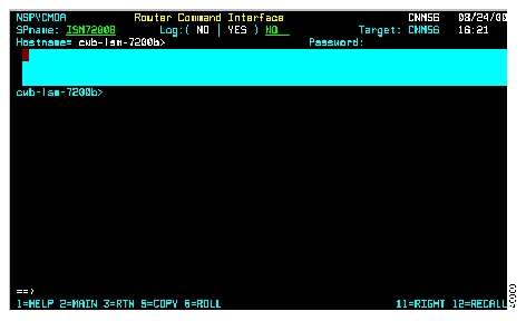
Figure 4-14 Router Command Interface Panel
ISM sends a RUNCMD to the router.
•
–
–
–
•
Step 4
Updating SNA Control Data
To update or change SNA control data, complete the following steps:
Step 1
•
•
Figure 4-15 ISM Resource Administration—SNA Router
Step 2
Step 3
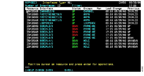
Displaying SNA Interface Status
Use the following procedure to display the current SNA interface status:
Step 1
Step 2
Figure 4-16 Interface Type Panel
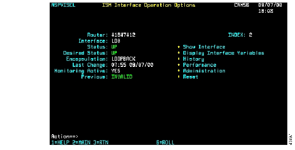
Displaying SNA Interface Details
To display details about a selected SNA interface, select an interface name on the Interface Status Panel and press Enter. The ISM Interface Operation Options panel ( Figure 4-17) is displayed.
Figure 4-17 ISM Interface Operation Options Panel
Enabling SNA Session Monitoring
To enable SNA session monitoring, complete the following steps:
Step 1
Step 2
Step 3
Step 4
Creating SNMP Resource Management Definitions
To create SNMP resource management definitions, complete the tasks in the following sections:
•
•
•
•
•
•
Adding SNMP Resource Definitions
Use the following procedure to add SNMP resource definitions:
Step 1
Step 2
•
Note
•
NSPSADD IP_address control_name
Where ip_address is the numeric form and control_name is a six- to eight-character name that manages ISM resources.
•
nspsadd 172.18.7.37 cwbc05ISM adds the resource with a CNTL name #18#7#37.
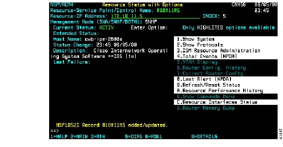
The Resource Status with Options panel for SNMP ( Figure 4-18) is displayed.
Figure 4-18 Resource Status With Options Panel—SNMP
Step 3
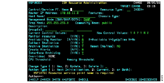
Figure 4-19 ISM Resource Administration Panel—SNMP
Collecting SNMP Resource Data
To contact and collect system data from an SNMP resource, complete the following steps:
Step 1
Step 2
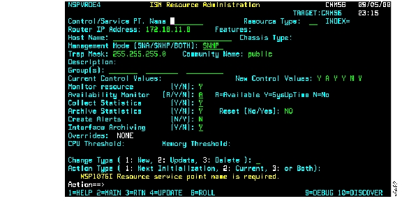
Figure 4-20 ISM Resource Administration Panel —SNMP, After Update
In Figure 4-20, the control name shown is created from a host name. When the resource is added dynamically, the control name is created from the IP address. (For example, 172.18.7.42 becomes #18#7#42.)
Creating an SNMP Resource Control Block
To create a control block and control file for an SNMP resource, press PF4 on the ISM Resource Administration panel for SNMP ( Figure 4-19) to display the Resource Status with Options panel for SNMP ( Figure 4-18). Data appears automatically in the required fields.
Adding SNMP Interfaces
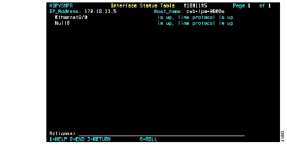
To add SNMP interfaces, on the Resource Status with Options panel for SNMP ( Figure 4-18), in the Enter Options field, type 2 (Show Protocols) and press Enter. The Interface Status Table panel ( Figure 4-21) is displayed.
Figure 4-21 Interface Status Table Panel
When ISM detects an SNMP resource, this panel displays the resource protocols.
When ISM does not detect an SNMP resource, the system creates a control block and control file for each resource.
Updating the Status in the Control Block
To update the status in the control block, complete the following steps:
Step 1
Step 2
Step 3
Step 4
Renaming an SNMP Resource Definition
To rename an SNMP device control (CNTL), complete the following steps:
Step 1
Figure 4-22 Resource Status Panel
Step 2
Step 3
Step 4
Step 5
Step 6
Step 7
Step 8
Step 9
Step 10
Step 11
Step 12
Step 13
Step 14
Enabling SNMP Session Monitoring
Use the following procedure to enable SNMP session monitoring:
Step 1
Step 2
Step 3
Step 4
Monitoring Resources Using the Standard Interface
You can monitor your resources using either the standard interface or by the NetView Web interface. This section describes how to use the standard interface to perform the following tasks:
•
•
•
•
•
•
•
•
For details on using the Web interface, see the "Displaying Resource Status Using the Web Interface" section.
Displaying Resource Status Using the Standard Interface
This section describes how to perform the following tasks:
•
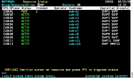
The ISM Status Summary panel ( Figure 4-23) displays the overall status of your resource in color-coded categories that reflect the number of resources (by type) with a particular status condition.
•
The Resource Status panel ( Figure 4-9) displays a list of all resource control names that are known to ISM in color-coded format to indicate status conditions and to diagnose problems.
•
Using the ISM Status Summary Panel from the Standard Interface
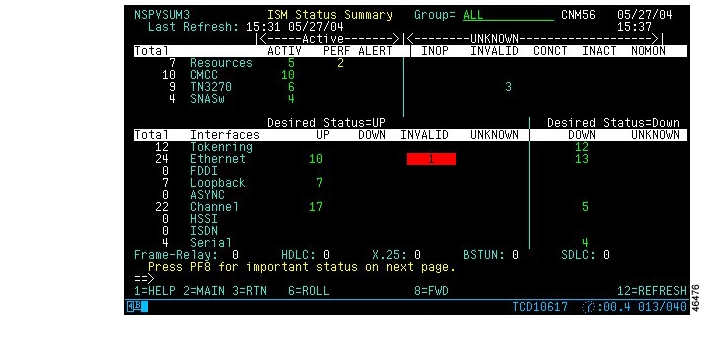
Use the ISM Status Summary panel ( Figure 4-23) to monitor the overall status of all your resources by type of condition.
Figure 4-23 ISM Status Summary—First Panel
The ISM Status Summary panel uses a color-coded display to indicate different types of status conditions. New alerts are shown in a colored box. After you view the resources with new alerts, or if you leave the ISM Status Summary panel, the colored box is removed. The number in the column representing the resources in that condition remains color-coded unless the status condition is removed.
You can access other information when monitoring resources using the ISM Status Summary panel, as follows:
•
•
Using the ISM Resource Status Panel from the Standard Interface
To view resource status and diagnose problems, use the Resource Status panel ( Figure 4-9). To access the Resource Status panel, select MGR on the ISM main menu panel, or select a resource on the ISM Status Summary panel, then press Enter.
You can perform the following tasks on the Resource Status panel:
•
•
•
•
Description of Status Types Using the Standard Interface
The color of the control name of a resource on the ISM Status Summary panel ( Figure 4-23) or ISM Resource Status panel ( Figure 4-9) indicates the condition of that resource. Table 4-1 lists the color and definition of each status.
Diagnosing Problems Using the Standard Interface
ISM provides a powerful diagnostic function that you can use to obtain information about the most critical problem affecting the resource. On the Resource Status panel ( Figure 4-9) or the Resource Status with Options panel ( Figure 4-10), press PF5 to display the diagnostic panel that ISM determines is best-suited to solve the resource's most critical problem.
For example, if an alert has been received from a resource (resource is displayed in pink and has an ALERT status), select the resource and press PF5 to display the appropriate panel to view the received alerts for that resource. If the problem is a hardware-related problem, ISM might open NPDA to show hardware status information from NetView.
Filtering Resources Using the Standard Interface
The Resource Status panel ( Figure 4-9) can display status information for up to 18 resources in a single view. If you have more than 18 resources, you can scroll forward or backward, or apply filters to display a subset of resources.
This section provides information on the following topics:
•
•
•
Filtering by Logical Groups Using the Standard Interface
Group filtering allows you to view the status for logically grouped resources. For example, a group may include all the resources located in a region or department, or those of a particular device type. The group to which a resource belongs is assigned by an ISM administrator when the resource is defined to ISM, and only an ISM administrator can filter resources by groups. For more information about assigning resources to groups, see the "Enabling Monitoring Options for Multiple Routers" section.
This section includes information on the following topics:
•
•
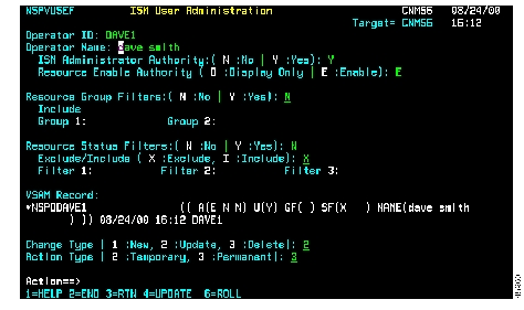
Filtering by Logical Groups in the ISM User Administration Panel Using the Standard Interface
To include filters for up to two resource groups on the ISM status panels, complete the following steps:
Step 1
Figure 4-24 ISM User Administration Panel
Step 2
Step 3
Step 4
Step 5
Step 6
Step 7
Filtering by Logical Groups From the Resource Status Panel Using the Standard Interface
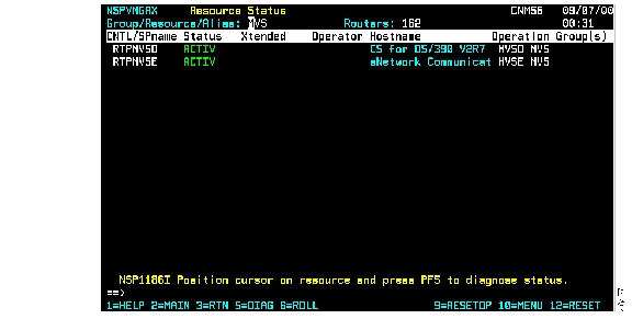
To view a logical group of resources from the Resource Status panel ( Figure 4-9), in the Group/Resource/Alias option at the top of the panel, type the name of the resource groups that you want to view and press Enter. The resources are displayed that belong to the filter groups that you specified, and that you are authorized to see. Figure 4-25 shows sample filtering for resources assigned to the group MVS.
Figure 4-25 Resource Status Panel with Group Filter
Filtering by Status Using the Standard Interface
Status filtering allows you to view status for resources that match, or do not match, a specified status. You can specify filtering of resources that match up to three different status types, and then display a Resource Status panel view that includes or excludes those resources.
To include or exclude resources that match the filter criteria (up to three status types) for viewing on the ISM status panels, complete the following steps:
Step 1
Step 2
Step 3
•
•
Step 4
Step 5
Step 6
Step 7
Filtering by Control Name Using the Standard Interface
You can filter the resources that you want to view on the Resource Status panel ( Figure 4-9).
In the Group/Resource/Alias field, enter the beginning characters of the control name you want to view, followed by an asterisk (*), and press Enter. (The asterisk acts as a wildcard, matching any remaining characters in the name.) Only the resources with control names that begin with the characters you specified are displayed. For example, to filter the display of all resources beginning with the characters cwb, type cwb* in the Group/Resource/Alias field.
Refreshing and Resetting Resources Using the Standard Interface
Although ISM automatically updates the status of the resources at the intervals specified by an ISM administrator in the ISM setup, you can manually refresh resource status information at any time between those intervals.
If you are an enabled ISM user, you can release and reset a resource from an operator who is logged in to a resource in enabled mode, or who is in a busy state with a resource.
You can refresh or check the status of a resource from the Resource Status panel ( Figure 4-9). Resources can be reset from the Resource Status panel depending upon where the cursor is positioned when you perform the reset operation.
•
If the Resource Status panel is currently showing a filtered view of resources, then only the resources shown in the filtered view are reset.
•
To refresh outdated resource status information, press PF12. You can also reset and check the status of a resource by selecting the resource and pressing Enter to display the Resource Status with Options panel ( Figure 4-10). Then, in the Enter Option field, type 9 and press Enter.
Viewing Resource Management Information Using the Standard Interface
There are several perspectives from which you can view the management information for a resource. The following sections describe the ways that you can collect and view the configuration of a resource:
•
•
•
•
Viewing SNA Resource Administration Definitions Using the Standard Interface
To view an ISM resource, complete the following steps:
Step 1
Step 2
Viewing SNA Resource Status from VTAM Using the Standard Interface
Complete the following tasks to view a resource as it is defined in VTAM:
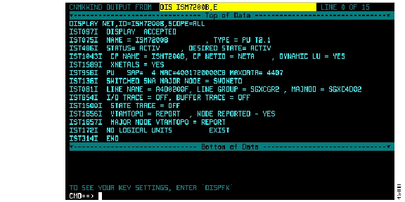
Step 1
Step 2
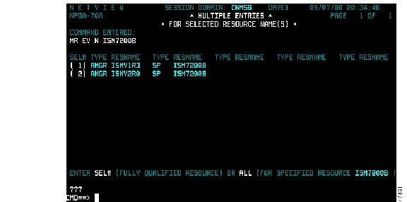
Figure 4-26 Output Panel Showing Resource Configuration in VTAM
Collecting and Archiving a Router Configuration Using the Standard Interface
If you are an enabled ISM user, you can collect the current configuration of a router and archive it. To collect a current configuration, you must first log in to the router in enable mode. You must know the router password, and if the router is using TACACS, you must have a user ID defined to TACACS to collect a router configuration.
Complete the following tasks to collect the current configuration of a resource:
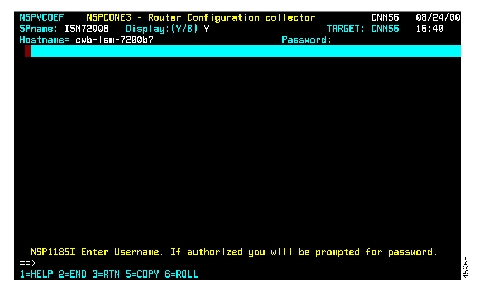
Step 1
Step 2
Figure 4-27 Router Configuration Collector Panel
Step 3
Step 4
Step 5
Step 6
Step 7
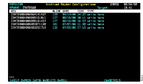
Viewing Archived Configurations Using the Standard Interface
You can display a list of archived configuration files for an SNA router, view the details of a specific configuration file, and use an archived configuration file for disaster recovery.
To display a list of archived configuration files, complete the following steps:
Step 1
Step 2
Figure 4-28 Archived Router Configurations Panel
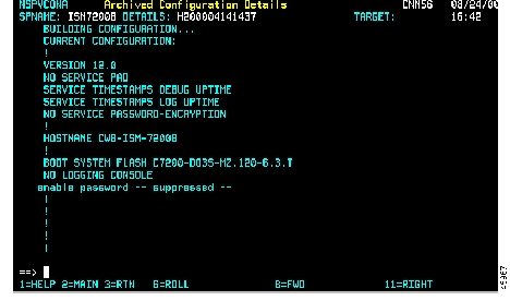
Step 3
Figure 4-29 Archived Configuration Details Panel
As an ISM security feature, if the command issued requires a password, the password is suppressed and not logged.
Monitoring Resource Performance Using the Standard Interface
This section describes the resource performance data that is available from ISM. It explains how to obtain the performance data that is useful in monitoring the performance of a resource.
You can use the following methods to monitor resource performance:
•
•
The following sections describe the ways that you can monitor resource performance:
•
•
Setting Resource Monitoring and Threshold Values Using the Standard Interface
If you are an ISM administrator, you can set the monitoring intervals and CPU and memory thresholds when you enable ISM Resource Management. Specifying a monitoring interval determines the time (in hours and minutes) when ISM queries and collects performance data from the resources in your network.
Specifying CPU and memory thresholds determines the level (expressed as a percentage of the CPU utilization and availability of free memory) that when exceeded will cause ISM to generate an alert. When a performance alert is generated, ISM displays PERF for the resource status.
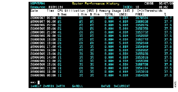
Viewing Router Performance History Using the Standard Interface
Once you have set the monitoring interval and CPU and memory threshold levels, ISM will measure the performance of the resources in your network using those values. The results are archived in the Router Performance History data set. Any ISM user can view the records archived for a specific resource on the Router Performance History panel. If you are an ISM administrator, you can set the record wrap counts for the data set in the ISM Resource Management setup. For more information about setting the record wrap counts, see the "Changing the Database IDs and Maximum Record Counts" section.
To view performance history records for a specific resource, complete the following steps:
Step 1
Step 2
Figure 4-30 Router Performance History Panel
This panel shows CPU utilization and memory usage statistics. Threshold values are shown at the top of the display columns. If a threshold is exceeded, the threshold is shown in yellow.
Viewing Hardware Alerts and Events Using the Standard Interface
Alerts generated by a resource that is being monitored by ISM are forwarded to the host by the service point configured in the resource. You can enable ISM to generate alerts for resources, interfaces, and CMCCs when thresholds are exceeded. For information about enabling alert generation in ISM, see the "Enabling Resource Alert Generation" section.
You can access NetView's Hardware Monitor Facility from within ISM to obtain a list of alerts generated by a specific resource and sent to NetView. For more information on using the NetView Hardware Monitor Facility, refer to the appropriate NetView operations manual.
You can perform the following tasks to view hardware alerts and events:
•
•
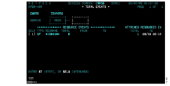
Displaying the Total Count of Events Using the Standard Interface
Complete the following tasks to display the total count of events in NetView's hardware monitor:
Step 1
Step 2
Figure 4-31 NetView Hardware Monitor Events Panel
Displaying the Most Recent Alerts Using the Standard Interface
To display a list of the most recent alerts in NetView's hardware monitor, complete the following steps:
Step 1
Step 2
Figure 4-32 NetView Hardware Monitor Alerts Panel
Using the Standard Interface for Logging In to Routers and Issuing Commands
You can use the ISM Router Command Interface panel ( Figure 4-33) to connect to a router and issue commands that you would normally have to issue in a Telnet session. However, ISM does not accept some commands, such as telnet. Additionally, the commands you can issue from the Resource Command Interface panel are based on your authority level, as defined in your operator profile and on the security implemented in the router.
Commands issued from the Router Command Interface panel are written to the NetView log. The name of the operator who issues a command is also recorded. However, as an ISM security feature, if the command issued requires a password, the password is suppressed and not logged. Also, if the command issued requests router configuration information, all security-sensitive data is suppressed and not logged.
This section contains information on the following topics:
•
•
•
•
•
Issuing Commands From the ISM Main Menu Panel Using the Standard Interface
To issue commands to a router from the ISM main menu panel ( Figure 4-1), complete the following steps:
Step 1
Step 2
Figure 4-33 Router Command Interface Panel
The Router Command Interface panel contains the following functional areas:
•
•
•
•
•
Step 3
•
•
Step 4
Step 5
Step 6
Issuing Commands From the Resource Status Panel Using the Standard Interface
To issue router commands from the Resource Status panel ( Figure 4-9), complete the following steps:
Step 1
Step 2
Step 3
•
•
Step 4
Step 5
Step 6
Issuing Router Show Commands Using the Standard Interface
ISM supports a set of Cisco IOS software show commands you can use to obtain additional information about a router. These commands are useful for monitoring and problem determination purposes.
To issue router show commands, complete the following steps:
Step 1
Step 2
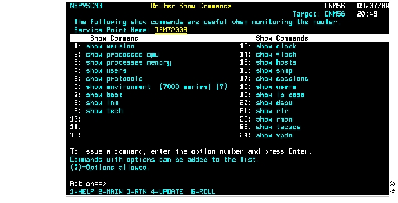
Figure 4-34 Router Show Commands Panel
Step 3
Using the Standard Interface for Adding Commands to the Router Show Commands Panel
If you are an ISM administrator, you can add Cisco IOS software show commands to the Router Show Commands panel ( Figure 4-34). (The show commands you add must be supported by Cisco IOS Release 11.0 and later.)
Complete the following tasks to add a Cisco IOS software show command to the Router Show Commands panel:
Step 1
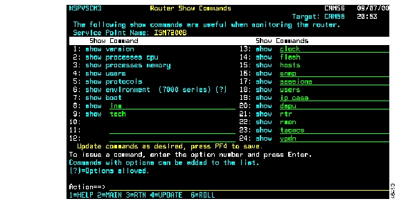
Figure 4-35 Router Show Commands—Update Mode Panel
Step 2
Step 3
Using the Standard Interface to Display Router Memory
To execute router show commands that display information about the router's memory configuration, use the Router Memory Dump Options panel.
To issue router memory commands, complete the following steps:
Step 1
Step 2
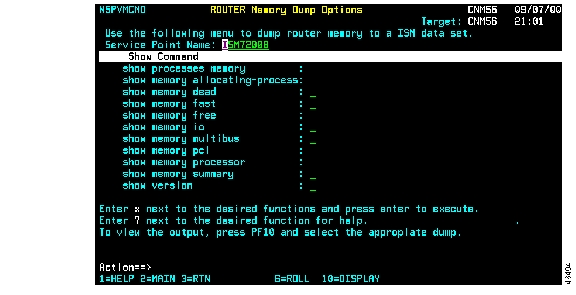
Figure 4-36 Router Memory Dump Options Panel
The following commands are displayed on the Router Memory Dump Options panel:
•
–
–
–
–
–
–
–
–
–
–
•
•
•
•
•
•
•
•
•
•
•
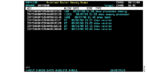
Step 3
Step 4
Figure 4-37 Archived Router Memory Dumps Panel
Each time you issue a command, a new record is created that contains the actual command output.
•
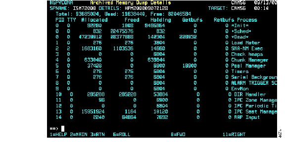
•
Figure 4-38 Archived Memory Dump Details Panel
Using the Web Interface to Monitor Resources
You can monitor your resources using either the standard interface or by the NetView Web interface. This section describes how to use the Web interface to perform the following tasks:
•
•
•
•
•
•
•
•
•
•
•
For details on using the standard interface, see the "Displaying Resource Status Using the Standard Interface" section.
Displaying Resource Status Using the Web Interface
This section describes the following tasks:
•
•
•
Using the ISM Status Summary Page from the Web Interface
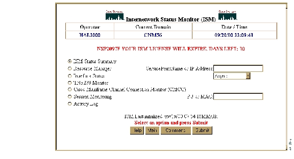
Use the ISM Status Summary page to monitor the overall status of all your resources by type of condition. To access this page, select ISM Status Summary on the ISM main menu page ( Figure 4-39), then click Submit.
Figure 4-39 ISM Main Menu Page
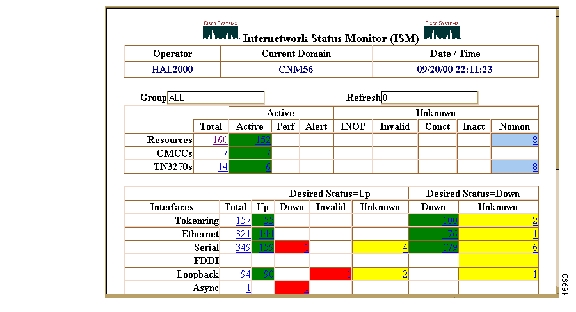
The ISM Status Summary page ( Figure 4-40) is displayed.
Figure 4-40 ISM Status Summary Page
The ISM Status Summary page uses a color-coded display to indicate different types of status conditions. You can access other information when monitoring resources using the ISM Status Summary page, as follows:
•
•
•
•
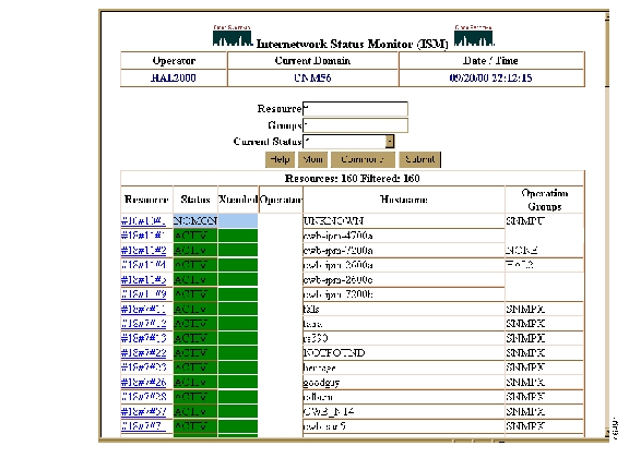
Figure 4-41 Resource Status Page
You can perform the following tasks on the Resource Status page:
•
•
•
•
Using the ISM Resource Status with Options Page from the Web Interface
To view resource status and perform other resource-related functions, use the Resource Status with Options page. To access this page, use one of the following procedures:
•
•
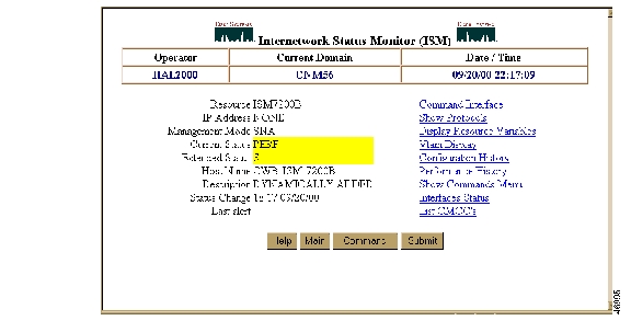
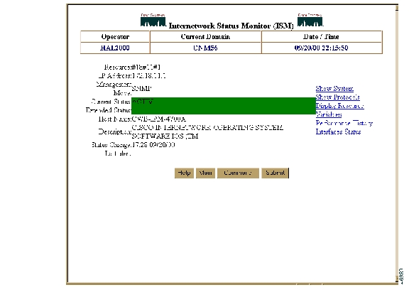
The Resource Status with Options page is displayed. Figure 4-42 shows the Resource Status with Options page for an SNA resource; Figure 4-43 shows the Resource Status with Options page for an SNMP resource.
Figure 4-42 Resource Status with Options Page—SNA
Figure 4-43 Resource Status with Options Page—SNMP
You can perform the following commands from the Resource Status with Options page:
•
•
•
•
•
•
•
•
•
•
Description of Status Types Using the Web Interface
The color of the service point name of a resource on the ISM Status Summary page ( Figure 4-40) or ISM Resource Status page ( Figure 4-41) indicates the condition of that resource. Table 4-2 lists the color and definition of each status:
Issuing Router Commands Using the Web Interface (SNA Only)
You can use the Command Interface page to connect to a router and issue commands that you would normally have to issue in a Telnet session. However, ISM does not accept some commands, such as telnet. Additionally, the commands you can issue from the Resource Command Interface page are based on your authority level, as defined in your operator profile and on the security implemented in the resource.
Commands issued from the Resource Command Interface page are written to the NetView log. The name of the operator who issues a command is also recorded. However, if the command issued requests router configuration information, all security-sensitive data is suppressed and not logged.
To issue commands to a router, complete the following steps:
Step 1
Step 2
Figure 4-44 Router Command Interface Page
For a detailed description of the fields on this page, see the online help.
Step 3
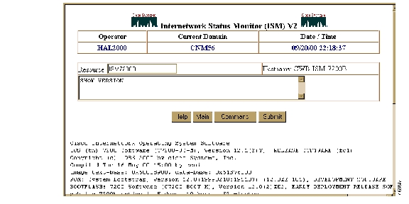
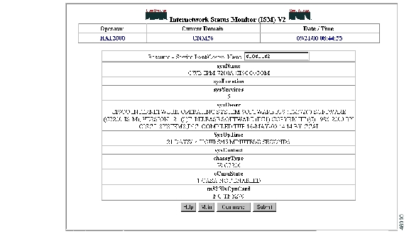
Showing the System (SNMP Only)
To display the Management Information Base (MIB) variables, select Show System on the Resource Status with Options page ( Figure 4-43) and click Submit. The System Status page ( Figure 4-45) is displayed.
Figure 4-45 System Status Page
For a detailed description of the fields on this page, see the online help.
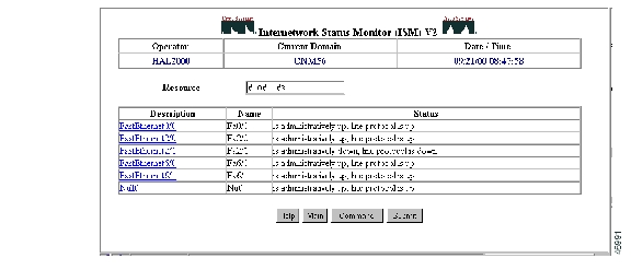
Displaying Protocol Status Using the Web Interface (SNA and SNMP)
To display the global and interface-specific status of any configured protocols, select Show Protocols on the Resource Status with Options page ( Figure 4-42) and click Submit. The Protocols Status page ( Figure 4-46) is displayed.
Figure 4-46 Protocols Status Page
For a detailed description of the fields on this page, see the online help.
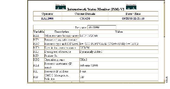
Displaying Resource Variables Using the Web Interface (SNA and SNMP)
To display detailed information about a resource's variables, including current values, select Display Resource Variables on the Resource Status with Options page ( Figure 4-42) and click Submit. The Resource Variables page ( Figure 4-47) is displayed.
Figure 4-47 Resource Variables Page
For a detailed description of the fields on this page, see the online help.
Viewing SNA Resource Status from VTAM Using the Web Interface (SNA Only)
Complete the following tasks to view a resource as it is defined in VTAM:
Step 1
Step 2
Figure 4-48 VTAM Resource Configuration Page
For a detailed description of the fields on this page, see the online help.
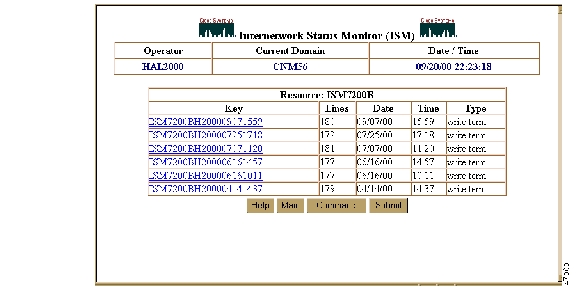
Viewing Archived Configurations Using the Web Interface (SNA Only)
To display a list of archived configuration files for an SNA resource, complete the following steps:
Step 1
Step 2
Figure 4-49 Archived Router Configurations Page
For a detailed description of the fields on this page, see the online help.
Step 3
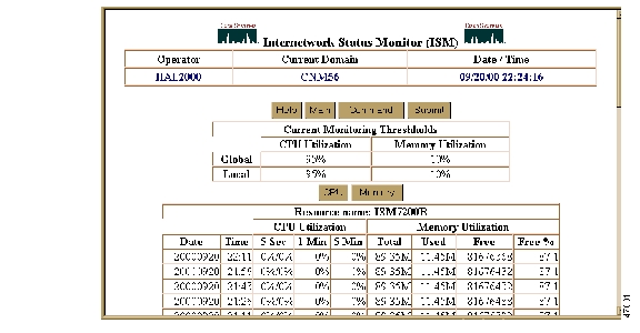
Viewing Router Performance History Using the Web Interface (SNA and SNMP)
ISM measures the performance of the routers in your network using the monitoring interval and CPU and memory threshold values you set. The results are archived in the Router Performance History data set. Any ISM user can view the records archived for a specific router on the Router Performance History page. If you are an ISM administrator, you can set the record wrap counts for the data set in the ISM Resource Management setup. For more information about setting the record wrap counts, see the "Changing the Database IDs and Maximum Record Counts" section.
To view performance history records for a specific router, complete the following steps:
Step 1
Step 2
Figure 4-50 Router Performance History Page
This page shows CPU utilization and memory usage statistics. Threshold values are shown at the top of the display columns. If a threshold is exceeded, the threshold is shown in yellow.
For a detailed description of the fields on this page, see the online help.
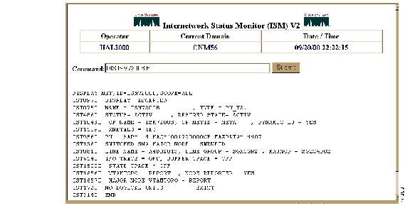
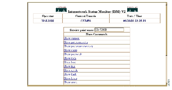
Issuing Router Show Commands Using the Web Interface (SNA Only)
ISM supports a set of Cisco IOS software show commands you can use to obtain additional information about a router. These commands are useful for monitoring and problem determination purposes.
To issue router show commands, complete the following steps:
Step 1
Step 2
Figure 4-51 Router Show Commands Page
For a detailed description of the fields on this page, see the online help.
Step 3
•
•
•
•
•
•
•
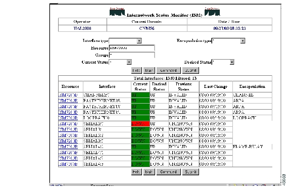
Displaying Interfaces Status (SNA and SNMP)
To display the status of any configured interfaces, select Interfaces Status on the Resource Status with Options page ( Figure 4-43) and click Submit. The Interfaces Type page ( Figure 4-52) is displayed.
Figure 4-52 Interfaces Type Page
For a detailed description of the fields on this page, see the online help.
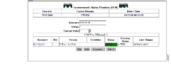
Displaying CMCC Status (SNA Only)
To display the status of any configured CMCCs, select List CMCCs on the Resource Status with Options page ( Figure 4-43) and click Submit. The CMCCs Status page ( Figure 4-53) is displayed.
Figure 4-53 CMCCs Status Page
For a detailed description of the fields on this page, see the online help.
![]()
![]()
![]()
![]()
![]()
![]()
![]()
![]()
Posted: Wed Oct 13 00:48:35 PDT 2004
All contents are Copyright © 1992--2004 Cisco Systems, Inc. All rights reserved.
Important Notices and Privacy Statement.