|
|

ISM monitors router status according to the monitoring intervals and performance thresholds that you can specify and provides alerts for problem conditions. In addition, ISM enables you to quickly go to the panel that provides you with the best information about the detected router condition so that you can quickly diagnose the source of the problem.
This chapter describes the following tasks to help you monitor your network routers in ISM:
Once you have enabled the Router Management application in ISM, you can disable monitoring of individual routers (including their associated interfaces, CMCCs, and DSPUs) when you set up the router monitoring options.
ISM's architecture provides two layers of router management control options---global and individual:
For information on setting up global router management options, see the "Setting Up Router Management Parameters" section.
For information on setting up router-specific management options, see the "Updating Individual Router Monitoring Options" section.
ISM provides two primary panels where you can monitor the status of your routers:
The ISM : Router List panel (Figure 5-1) shows all routers currently defined to ISM, with details of their current status and settings. This panel is the basis of your day-to-day router management activities. To define a new router to ISM, use the F4 (Add) function (see the "Adding and Updating Router Definitions" section).
To access the ISM : Router List panel, type R in the Select Option field on the ISM : Monitoring Menu panel and press Enter.
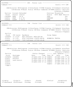
The actions displayed on this panel are the most commonly used ones. To display a complete list of actions available, type ? next to a router and press Enter. You can then select an action from this list to apply to the router.
There are different types of functions available by using the actions on the ISM : Router List panel:
Table 5-1 describes the administration functions available from the ISM : Router List panel. See also the "Adding and Updating Router Definitions" section.
| Task | Action | Result |
|---|---|---|
Browse a router's definition | B or S | The ISM : Router Administration panel (Figure 5-3) is displayed for the selected router, allowing you to browse its definition. |
Delete a router | D (E) | A message is displayed, requesting confirmation of the delete. |
Add a router | F4 | The ISM : Router Administration panel (Figure 5-3) is displayed blank, allowing you to define a new router to ISM. |
Update a router's definition | U (E) | The ISM : Router Administration panel (Figure 5-3) is displayed for the selected router, allowing you to update its definition. |
Table 5-2 describes the basic diagnostic functions available from the ISM : Router List panel.
| Task | Action | Result |
|---|---|---|
Discover a router | CHK | ISM rediscovers the router to identify its current resources (interfaces, CMCCs, and DSPUs). |
Apply various commands to a router | CI | The ISM : Command Interface panel (Figure 5-13) is displayed. |
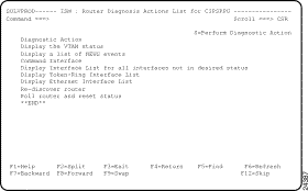
Diagnose a router condition | DR | The ISM : Router Diagnosis Actions List panel is displayed, showing actions that you can select to diagnose and resolve the router's problems. See the "Diagnosing Problems" section. |
View NEWS events for a router | EV | The NEWS : Events Review panel is displayed, where you can select an event to view its details or configuration, to raise or view a problem, or to delete. The EV action passes control to the NEWS application, and can result in a display with no records, or with records generated by applications other than ISM. ALERT status on a router can also be caused by another application. The EV action displays NEWS records for this event only if it is generated under the service point name of the router. Note This action is not available on remote systems. |
Issue the show protocols command to a router | P | The ISM : Command Interface panel (Figure 5-13) is displayed, with a formatted display of the show protocols and a fast path to the show interface display for each protocol. |
R | ISM polls the router and resets its status | |
Show commands for a router | SH | The ISM : Router Show Commands panel (Figure 5-14) is displayed. |
View a VTAM display for a router | V | The ISM : Command Interface panel (Figure 5-13) is displayed, with the VTAM display command entered. |
Table 5-3 describes the advanced diagnostic functions available by using actions on the ISM : Router List panel.
| Task | Action | Result |
|---|---|---|
Collect a router configuration | CO (E) | The ISM : Router Configuration Command panel (Figure 5-9) is displayed, where you can do the following:
|
View a router configuration | CV (E) | The ISM : Config. Records for Router panel is displayed, where you can select individual configuration records to view or delete. |
Request a memory dump for a router | DU | The ISM : Dump Types List for router panel (Figure 5-16) is displayed, with a selection list of all memory dump types that can be requested. |
View memory dumps for a router | DV | The ISM : Stored Dumps List panel (Figure 5-17) is displayed. This allows you to select individual dumps to view or delete. |
Table 5-4 describes the history function available from the ISM : Router List panel. See also the "Viewing Router Performance History".
| Task | Action | Result |
|---|---|---|
View a router's performance history | H | The ISM : Router Performance History panel (Figure 5-7) is displayed. |
Table 5-5 describes the other monitoring lists available from the ISM : Router List panel. See also Chapter 7, "Monitoring CMCCs," and Chapter 6, "Monitoring Interfaces."
| Task | Action | Result |
|---|---|---|
View CMCCs for a router | CM | The ISM : CMCC List panel (Figure 7-1) is displayed, with a selection list of all CMCCs for the selected router |
View interfaces for a router | I | The ISM : Interface List panel (Figure 6-4) is displayed, with status details for all interfaces for the selected router |
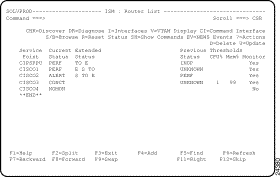
The color of the service point name of a router on the ISM : Router List panel (Figure 5-1) indicates the status of that router. Table 5-6 lists the color and definition of each status.
| Color | Status | Definition | Status Type |
Green | ACTIV | ISM can communicate with the router and the router is ready to receive commands. All router functions are available (VTAM status is ACTIV) | VTAM |
Pink | ALERT | The router is active, but an alert was detected through SOLVE:Netmaster's NEWS facility for a router resource managed by the router service point. | ISM |
Red | CONCT | Router is not connected to VTAM (VTAM status is CONCT) | VTAM |
Green | INACT | An operator has inactivated the router in VTAM (VTAM status is INACT) | VTAM |
Red | INOP | The router is active, but failed to respond to ISM. | ISM |
Turquoise | INVALID | Service point is unknown to VTAM (VTAM definition does not exist) | VTAM |
Blue | NOMON | Monitoring and history are disabled for the router and its subordinate interfaces and CMCCs. | ISM |
Yellow | PERF | Router is active, but one of the following problems exists:
| ISM |
White | UNKNOWN | Router is awaiting its first poll or ISM was unable to determine the status of the router. | ISM |
If the router status is PERF the Extended Status provides additional information why the router is in degraded mode. If the extended status is an abbreviation of an interface type, it means that an interface of that type is not in the desired status. Table 5-7 lists the descriptions of each extended status.
| Status | Description |
|---|---|
AS | Asynchronous interface not in desired state. |
AT | ATM interface not in desired state. |
C | Channel interface not in desired state. |
E | Ethernet interface not in desired state. |
FA | Fast Ethernet interface not in desired state. |
FD | FDDI interface not in desired state. |
H | HSSI interface not in desired state. |
I | ISDN interface not in desired state. |
L | Loopback interface not in desired state. |
P | Router degraded---router exceeds CPU or memory threshold. |
Q | Router degraded---CMCC exceeds CPU or memory threshold. |
S | Serial interface not in desired state. |
TO | Token Ring interface not in desired state. |
TU | Tunnel interface not in desired state. |
If the router is already connected to the mainframe and communicating with VTAM, you can choose one of two options to create the new router definition:
When ISM detects a new router, it recognizes and establishes the VTAM definition member and major node for the router record in ISM. This information is necessary for successful monitoring of the router.
Use the following procedure to create a new router definition for a router that has not already been discovered by ISM:
Step 1 On the ISM : Router List panel (Figure 5-2), press F4.
The ISM : Router Administration panel is displayed (Figure 5-3) in Add mode.
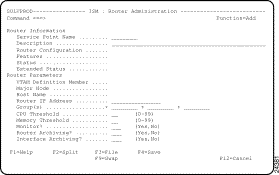
Step 2 Enter details in the two mandatory Router Information input fields: Service Point Name and Description.
For information about fields on this panel, press F1.
Step 3 To enable or disable monitoring, type Yes or No in the mandatory Router Parameters input field: Monitor?.
Step 4 To enable or disable router archiving or interface archiving, type Yes or No in the two mandatory Router Parameters input fields:
Step 5 Optionally, type values in the Router IP Address field.
Step 6 Optionally, to allocate this router to one or more groups for monitoring, type the name of one, two, or three groups in the Group(s) field(s).
If you do not specify a group, the router is added to the default group.
Step 7 Optionally, to set individual thresholds for monitoring this router, type the required threshold values in the CPU Threshold and Memory Threshold fields.
The default thresholds are the global thresholds set on the Parameter Administration panels.
Step 8 Press F3 to file the router details.
ISM populates the remaining fields. ISM then discovers the new router, together with its current resources (interfaces, CMCCs, and DSPUs).
Step 9 Pressing F3 (in Step 8) exits the panel. To modify the discovered fields, update a record by typing U next to the service point name and press Enter.
Step 10 Type new details in the fields that you want to change.
Step 11 Press F3 to file the router details.
To set up router monitoring for an individual router, complete the following steps:
Step 1 On the ISM : Router List panel, type U beside the service point name of the router that you want to modify and press Enter.
The ISM : Router Administration panel is displayed (Figure 5-3) in Update mode.
Step 2 To allocate this router to one or more groups for monitoring, type the name of one, two, or three groups in the Group(s) fields.
Step 3 To enable or disable router monitoring for this router, type Yes or No in the Monitor? field.
Step 4 To enable or disable router archiving for this router, type Yes or No in the Router Archiving? field.
Step 5 To enable or disable interface archiving for this router, type Yes or No in the Interface Archiving? field.
Step 6 To set individual thresholds for monitoring this router, type the required threshold values in the CPU Threshold and Memory Threshold fields.
Step 7 Press F3 to file the changes that you have made.
The default router monitoring interval is 15 minutes (00:15). Cisco recommends 2 hours (02:00).
If threshold settings are specified, it means that ISM indicates a performance alert (status of PERF) for the router when the following conditions occur:
You can set up the CPU and memory thresholds for all routers on the ISM : Router Management Parameters panel. For more information about setting up the global router management options, see the "Setting Up ISM Management Applications" section.
You can override the router CPU and memory global thresholds that are set up for all routers on an individual-router basis on the ISM : Router Administration panel (Figure 5-3). Type the percentages that you want to update in the CPU Threshold and Memory Threshold options.
For more information on updating individual router definitions, see the "Updating Individual Router Monitoring Options" section.
For more information on setting up router alert generation, see the "Setting Up Router Management Parameters" section.
For more information about enabling the ISM Interface Monitoring application and selecting the types of interfaces for ISM to monitor, see the "Setting Up ISM Management Applications" section.
You can set up router interface archiving for an individual router on the ISM : Router Administration panel (Figure 5-3). Type Yes or No in the Interface Archiving? field.
For more information about monitoring interfaces, see the "Monitoring Interfaces" chapter.
ISM provides a powerful diagnostic function that you can use to obtain information about the most critical problem affecting the router. From the ISM : Router List panel (Figure 5-1), you can type DR next to a router and press Enter to display the ISM : Router Diagnosis Actions List for Router panel (Figure 5-4). This panel displays a list of actions that you can perform to diagnose problems with the selected router. The list of actions available varies, depending on the current status and extended status of the router. You can select one or more actions to perform.
The following actions are always provided:
The following actions are provided depending on the extended status:
For example, suppose the selected router is in PERF status with extended status TO E, where:
Then the panel is displayed with the actions shown in Figure 5-1.
You can apply filters based upon the following criteria:
You can filter the routers that you want to view by using the Service Point Name field on the ISM : Monitoring Menu panel (Figure 5-5).
To filter routers from the ISM : Monitoring Menu panel, in the Service Point Name field, type the beginning characters of the service point name that you want to view, followed by an asterisk (*) (to allow a match for any remaining characters in the name), and press Enter. Only the routers with service point names that begin with the same characters you specified are displayed. For example, to filter the display of all routers beginning with the characters cwb, type cwb* in the Service Point Name field.
Group filtering allows you to view the status for logically grouped routers. For example, a group may include all the routers located in a region or department, or those of a particular device type. The group to which a router belongs is assigned by an ISM administrator when the router is defined to ISM, and only an ISM administrator can define router filters by groups. For more information about assigning routers to groups, see the "Assigning Routers to Management Groups" section.
To view a logical group of routers from the ISM : Monitoring Menu panel, complete the following steps:
Step 1 From the ISM : Primary Menu panel, type M in the Select Option field and press Enter. The ISM : Monitoring Menu panel is displayed (Figure 5-5).
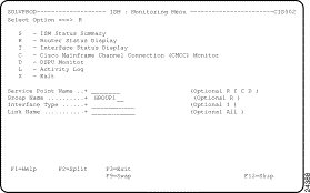
Step 2 In the Select Option field, type R.
Step 3 In the Group Name field, specify the router group name for which you want to view routers and press Enter. You can enter a question mark (?) to display a selection list of group names.
The ISM : Router List panel is displayed, listing routers that belong to the filter group that you specified.
 | Tips |
You can determine the group to which a router belongs from the ISM : Router List panel (Figure 5-1) or by viewing the definition of a router (Figure 5-3).
Status filtering allows you to view the status for routers grouped by status. For example, you may want to include all routers in a particular status, or exclude all routers in a particular status. Do this by defining a status filter on the ISM : Status Filter Details panel (Figure 5-6), as described in the following section.
Step 1 On the ISM : Monitoring Menu panel (Figure 5-5), type SF in the Select Option field and press Enter. The ISM : Status Filter Details panel (Figure 5-6) is displayed, showing details for your user ID.
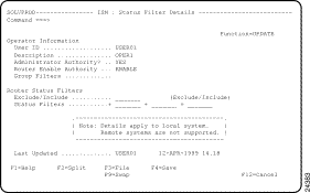
Step 2 In the Exclude/Include field, type I or E to indicate whether you are excluding or including routers of the specified status in your monitoring.
Step 3 In one or more Status Filters fields, type the status values that you want to exclude or include.
If you are an enabled ISM user, you can rediscover a router and refresh its attributes (interfaces, CMCCs, and DSPUs). You do this by using the Discover action (CHK) on the ISM : Router List panel.
If you are an enabled ISM user, you can reset a router from an operator who is logged in to a router in enabled mode or who is in a busy state with a router. You do this by using the Reset action (R) on the ISM : Router List panel.
You can refresh or check the status of a router from the ISM : Router List panel.
To refresh outdated router status information on the ISM : Router List panel, press F6.
To reset a router from the ISM : Router List panel, type R next to a router and press Enter. The selected router is reset.
To disable archiving for a router, use the ISM : Router Administration panel (Figure 5-3). Type No in the Interface Archiving option.
For more information on updating individual router definitions, see the "Updating Individual Router Monitoring Options" section.
You can remove the history and performance records for an individual router from the history database using the Delete History function on the ISM : Router Performance History panel (Figure 5-7).
Complete the following tasks to delete router performance history records for an individual router:
Step 1 On the ISM : Router List panel (Figure 5-2), type H beside a router entry and press Enter. The ISM : Router Performance History panel (Figure 5-7) for the selected router is displayed.
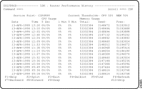
Step 2 On the ISM : Router Performance History panel, press F4.
The ISM : Router Management History Delete panel is displayed.
Step 3 Press F6 to confirm the delete.
ISM displays a message confirming that the router performance history records for the selected router have been deleted.
For more information on resetting the history database, see the "Deleting History and Performance Records" section. Another method of applying changed wrap counts to previously defined routers and interfaces is to delete the router definition and redefine the router to ISM.
For more information about changing the wrap counts, see the "Setting Up ISM Database Parameters" section.
Complete the following tasks to view a router as it is defined in VTAM:
Step 1 On the ISM : Router List panel (Figure 5-1), type V next to the router name and press Enter. The NCS : Node Display panel is displayed (Figure 5-8), showing the router connection as it is defined in VTAM.
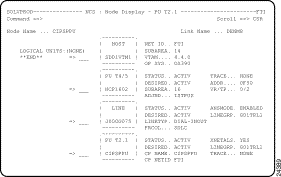
Step 2 If you want further VTAM information, you can enter VTAM or NCS commands in the input field next to a node. For further information about using these commands, press F1 to view the online help.
Use the ISM : Router List (Figure 5-1) panel to view a router as it is defined in ISM. In the Enter Option field, type S or B next to a router name and press Enter. The ISM : Router Administration panel (Figure 5-3) for the selected router is displayed.
Complete the following tasks to collect the current configuration of a router:
Step 1 On the ISM : Router List panel, type CO next to the router name for which you want to view ISM management information and press Enter. The ISM : Router Configuration Command panel (Figure 5-9) is displayed.
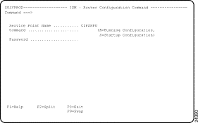
Step 2 In the Command field, type the one of the following codes for the configuration request:
Step 3 In the Password field, type the enable password and press Enter.
When the request has been completed, a message is displayed showing the number of records collected and stored.
Step 4 When you are notified that the router configuration for the router has been saved, press Enter. The configuration you collected is archived.
Step 5 Press F3 to terminate your enabled session to the router.
Complete the following tasks to display a list of archived configuration files:
Step 1 On the ISM : Router List panel, type CV next to the router name for which you want to view ISM management information and press Enter. The ISM : Configuration Records for Router panel (Figure 5-10) is displayed.
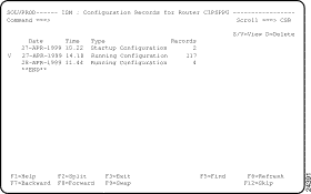
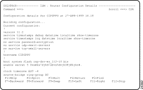
Step 2 To view the details of a configuration file, type S or V next to the record that you want to view and press Enter. The ISM : Configuration Details panel is displayed (Figure 5-11) for the selected record.
Step 3 Locate specific details within the router configuration record on this panel by scrolling (press F7, F8, F10, or F11) or by finding text-strings (press F5).
You can use the following methods to monitor the performance of a router:
For more information on setting up the router monitoring and threshold options, see the "Setting Up the Router Monitoring Interval" section and "Setting Up the Router CPU and Memory Thresholds" section.
To view performance history records for a specific router, type H next to the router's service point name on the ISM : Router List and press Enter. The Router Performance History panel (Figure 5-12) is displayed for the specified router.
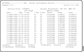
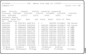
The ISM : Router Performance History panel shows CPU usage and memory usage statistics. Threshold values are shown at the top of the display columns. If thresholds are exceeded, the line containing the record is shown in yellow.
From the ISM : Router Performance History panel you can delete the displayed records from the performance history database. To delete the records for the selected router from the performance history database, press F4 (DelHist). The ISM : Router Management History Delete panel is displayed, prompting you to confirm or cancel your deletion request.
If you have enabled alert generation, alerts generated by a router that is being monitored by ISM are forwarded to the host by the service point configured in the router. You can enable ISM to generate alerts for routers, interfaces, and CMCCs when thresholds are exceeded. For information about enabling alert generation in ISM, see the "Setting Up Router Alert Generation" section.
You can access SOLVE:Netmaster's NEWS facility from within ISM to obtain a list of alerts generated by a specific router or router resource and forwarded to SOLVE:Netmaster. For more information on using SOLVE:Netmaster's NEWS facility, see the SOLVE:Netmaster User's Guide.
For details of how to use SOLVE:Netmaster's NEWS facility to view details of alerts, see the SOLVE:Netmaster User's Guide or press F1 to view the online help for the NEWS panels.
Complete the following tasks to issue commands to a router from the ISM : Router List panel:
Step 1 On the ISM : Router List panel, type CI next to the service point name of the router and press Enter. The ISM : Command Interface panel (Figure 5-13) is displayed.
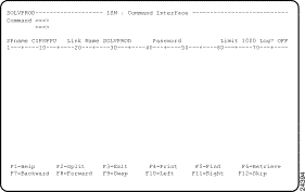
Step 2 If you want to execute the command on a remote system, type the remote system ID in the Link Name field.
Step 3 If a password is required for the command that you entered, type the password in the Password field.
Step 4 To specify how output from the router command is to be handled, specify one of the following options:
Step 5 In the Command field, type the router command and press Enter.
The command output is displayed on the panel.
Step 6 To recall the last command that you issued, press F6.
ISM provides a list of commonly used Cisco IOS software show commands that you can use to obtain additional information about a router. These commands are useful for monitoring and problem determination purposes. If you are an ISM administrator, you can add show commands to the ISM : Router Show Commands panel (Figure 5-14).
The following commands are displayed on the ISM : Router Show Commands panel:
Complete the following tasks to issue router show commands:
Step 1 On the ISM : Router List panel, type SH next to the router for which you want to view ISM management information and press Enter. The ISM : Router Show Commands panel is displayed (Figure 5-14).
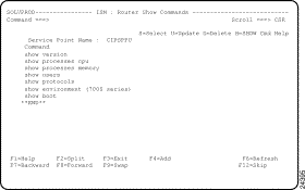
Step 2 To issue a command, type S next to the command and press Enter.
If you are an ISM administrator, you can add Cisco IOS software show commands to the Router Show Commands panel (Figure 5-14). These show commands must be supported by Cisco IOS Release 11.0 and later.
Complete the following tasks to add a Cisco IOS software show command to the ISM : Router Show Commands panel:
Step 1 On the ISM : Router Show Commands panel, press F4 to display an update panel. The ISM : Add Router SHOW Commands panel is displayed (Figure 5-15).
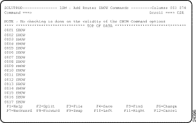
Step 2 In the free-format data-entry field following the show keyword, type the parameter or parameters that correspond to the command that you are adding and press F3. You are returned to the ISM : Router Show Commands panel.
Step 3 On the ISM : Router Show Commands panel, press F6. The ISM : Router Show Command panel is redisplayed with the command that you added.
The following commands are displayed on the ISM : Dump Types List panel (Figure 5-16):
If you want to issue a router memory command to request a memory dump but do not want to view the output yet, you can use the DU option to request a dump and add it to the list of stored dumps. When you want to view it, you can select it from the list of stored dumps.
To request a memory dump and view it later, perform the following steps:
Step 1 On the ISM : Router List panel, type DU next to the service point name of the router for which you want to view ISM management information and press Enter. The ISM : Dump Types List panel is displayed (Figure 5-16) for the selected router.
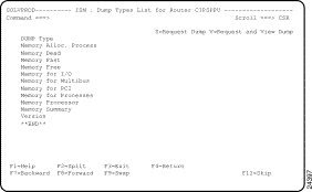
Step 1 On the ISM : Dump Types List panel, type S next to a memory dump type and press Enter.
ISM executes the corresponding command and stores the output so that it can be viewed from the ISM : Stored Dumps List. It also displays a completion message against the selected dump type, advising how many records have been stored as a result of this dump.
Step 2 When you are ready to view the output of a memory dump, on the ISM : Router List panel, type V next to the service point name of the router for which you want to view ISM management information and press Enter. The ISM : Stored Dumps List is displayed (Figure 5-17).
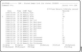
Step 3 To view details of a memory dump, type S or V next to a dump and press Enter.
A memory dump panel is displayed, whose format varies, depending on the type of memory dump. For example, selecting a Memory Free dump displays an ISM : Memory Free Dump panel (Figure 5-18).
Step 4 Locate specific details within the command output on this panel by scrolling (press F7, F8, F10, or F11) or by finding text-strings (press F5).
Step 5 To delete a memory dump from the ISM : Stored Dumps List, type D next to a dump and press Enter. A message is displayed, prompting you to confirm or cancel your delete request.
To request a memory dump and view it immediately, perform the following steps:
Step 1 On the ISM : Router List panel, type DU next to the service point name of the router for which you want to view ISM management information and press Enter. The ISM : Dump Types List panel is displayed (Figure 5-16) for the selected router.
Step 2 To request and view a memory dump, type V next to a memory dump type and press Enter. ISM executes the corresponding command.
If the dump finds any records to process, ISM displays the command output on a memory dump panel. The format of this panel varies, depending on the type of memory dump. For example, selecting a Memory Free dump displays an ISM : Memory Free Dump panel (Figure 5-18) for the selected router.
If the dump finds no records to process, ISM displays a completion message against the selected dump type, advising that the number of records stored as a result of this dump is zero.
![]()
![]()
![]()
![]()
![]()
![]()
![]()
![]()
Posted: Tue Aug 24 12:06:55 PDT 1999
Copyright 1989-1999©Cisco Systems Inc.