|
|

Table Of Contents
DLP-A507 View OC-N PM Parameters
DLP-A509 Provision CE-1000-4 Ethernet Ports
DLP-A510 Provision a DS-3 Circuit Source and Destination
DLP-A512 Change Node Access and PM Clearing Privilege
DLP-A513 Provision CE-100T-8 and CE-MR-10 Ethernet Ports
DLP-A514 Provision CE-100T-8, CE-1000-4, and CE-MR-10 POS Ports
DLP-A517 View Alarm or Event History
DLP-A518 Create a New or Cloned Alarm Severity Profile
DLP-A519 Apply Alarm Profiles to Ports
DLP-A520 Delete Alarm Severity Profiles
DLP-A521 Modify Alarm, Condition, and History Filtering Parameters
DLP-A522 Suppress Alarm Reporting
DLP-A523 Discontinue Alarm Suppression
DLP-A524 Download an Alarm Severity Profile
DLP-A526 Change Line and Threshold Settings for the DS3i-N-12 Cards
DLP-A527 Change the OC-N Card ALS Maintenance Settings
DLP-A528 Change the Default Network View Background Map
DLP-A529 Delete Ethernet RMON Alarm Thresholds
DLP-A530 Install the Tie-Down Bar
DLP-A533 Create Ethernet RMON Alarm Thresholds
DLP-A534 Provision OSI Routing Mode
DLP-A535 Provision or Modify TARP Operating Parameters
DLP-A536 Add a Static TID to NSAP Entry to the TARP Data Cache
DLP-A537 Remove a Static TID to NSAP Entry from the TARP Data Cache
DLP-A538 Add a TARP Manual Adjacency Table Entry
DLP-A539 Provision OSI Routers
DLP-A540 Provision Additional Manual Area Addresses
DLP-A541 Enable the OSI Subnet on the LAN Interface
DLP-A542 Create an IP-Over-CLNS Tunnel
DLP-A543 Remove a TARP Manual Adjacency Table Entry
DLP-A544 Change the OSI Routing Mode
DLP-A545 Edit the OSI Router Configuration
DLP-A546 Edit the OSI Subnetwork Point of Attachment
DLP-A547 Edit an IP-Over-CLNS Tunnel
DLP-A548 Delete an IP-Over-CLNS Tunnel
DLP-A549 View IS-IS Routing Information Base
DLP-A550 View ES-IS Routing Information Base
DLP-A551 Manage the TARP Data Cache
DLP-A552 Adjust the Java Virtual Memory Heap Size
DLP-A553 Upgrade DS1 or DS3-12 Cards in a 1:N or 1:1 Configuration to High-Density Electrical Cards
DLP-A553 Upgrade DS3XM-6 Cards in a 1:1 Configuration to High-Density DS3XM-12 Electrical Cards
DLP-A554 Upgrade EC-1 Cards in a 1:1 Configuration to DS3/EC1-48 Cards
DLP-A555 Set Up SDH External or Line Timing
DLP-A556 Provision the Card Mode for ML-Series Ethernet Cards
DLP-A557 View Multirate PM Parameters
DLP-A558 Provision the Designated SOCKS Servers
DLP-A560 Create an Optimized 1+1 Protection Group
DLP-A561 Modify an Optimized 1+1 Protection Group
DLP-A562 View ML-Series RPR Span PM Parameters
DLP-A563 Configure an Automatically Routed BLSR DRI
DLP-A564 Configure a Manually Routed BLSR DRI
DLP-A565 Set Up a Solaris Workstation for a Craft Connection to an ONS 15454
DLP-A566 Install the CTC Launcher Application from a Release 8.0 Software CD
DLP-A567 Install the CTC Launcher Application from a Release 8.0 Node
DLP-A568 Connect to ONS Nodes Using the CTC Launcher
DLP-A569 Create a TL1 Tunnel Using the CTC Launcher
DLP-A570 Create a TL1 Tunnel Using CTC
DLP-A571 View TL1 Tunnel Information
DLP-A572 Edit a TL1 Tunnel Using CTC
DLP-A573 Delete a TL1 Tunnel Using CTC
DLP-A574 Provision a PPM on the MRC-12 or MRC-2.5G-4 Card
DLP-A575 Provision the Optical Line Rate on the MRC-12 or MRC-2.5G-4 Card
DLP-A576 Change the Optical Line Rate on the MRC-12 or MRC-2.5G-4 Card
DLP-A577 Delete a PPM from the MRC-12, MRC-2.5G-4, or OC192-XFP Card
DLPs A500 to A599
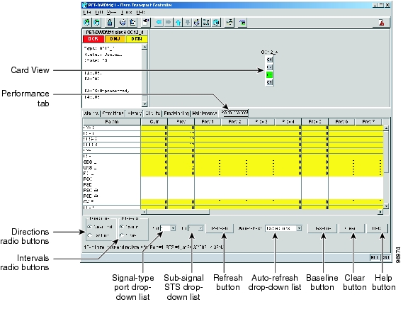
DLP-A507 View OC-N PM Parameters
Step 1
In node view, double-click the OC-N card where you want to view PM counts. The card view appears.
Step 2
Figure 22-1 Viewing OC-N Card Performance Monitoring Information
Step 3
Step 4
Step 5
Step 6
Step 7
DLP-A509 Provision CE-1000-4 Ethernet Ports
Note
Step 1
Step 2
Step 3
•
•
Note
•
•
•
•
Step 4
Step 5
a.
b.
Note
Step 6
DLP-A510 Provision a DS-3 Circuit Source and Destination
Note
Step 1
Step 2
Step 3
Step 4
Step 5
Step 6
Step 7
Step 8
Step 9
Step 10
Step 11
DLP-A512 Change Node Access and PM Clearing Privilege
Step 1
Step 2
•
–
–
–
–
•
Step 3
•
•
•
Step 4
Step 5
Step 6
Step 7
In the TCC CORBA (IIOP/SSLIOP) Listener Port area, choose a listener port option:
•
•
•
Step 8
Step 9
Step 10
DLP-A513 Provision CE-100T-8 and CE-MR-10 Ethernet Ports
Note
Step 1
Step 2
Step 3
•
•
•
•
•
•
•
Note
Note
Step 4
Step 5
a.
b.
Note
Step 6
DLP-A514 Provision CE-100T-8, CE-1000-4, and CE-MR-10 POS Ports
Note
Step 1
Step 2
Step 3
•
•
•
•
Note
Note
Step 4
Step 5
a.
b.
Step 6
DLP-A517 View Alarm or Event History
Step 1
Step 2
a.
b.
If you check the Alarms check box, the node's alarm history appears. If you check the Events check box, the node's Not Alarmed and transient event history appears. If you check both check boxes, you will retrieve node history for both alarms and events.
c.
Note
Tip
Step 3
a.
b.
Alarms and conditions (events) raised during the current session appear.
Step 4
a.
b.
Note
c.
d.
If you check the Alarms check box, the node's alarm history appears. If you check the Events check box, the node's Not Alarmed and transient event history appears. If you check both check boxes, you will retrieve node history for both alarms and events.
Note
Raised and cleared alarm messages (and events, if selected) appear.
Step 5
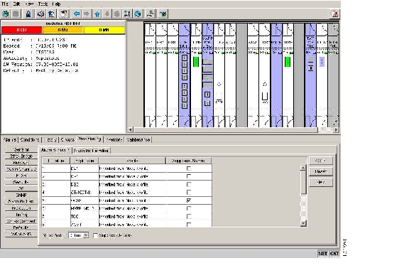
DLP-A518 Create a New or Cloned Alarm Severity Profile
Step 1
Step 2
Figure 22-2 Node View Alarm Profile Editor
Step 3
Step 4
Step 5
a.
b.
Step 6
a.
b.
c.
Note
Step 7
The alarm severity profile appears in the Alarm Profiles window. The alarm profile list contains a master list of alarms that is used for a mixed node network. Some of these alarms might not be used in all ONS nodes.
Step 8
Step 9
Tip
Step 10
Profile names must be unique. If you try to import or name a profile that has the same name as another profile, CTC adds a suffix to create a new name. Long file names are supported.
Step 11
A new alarm profile (named in Step 10) is created. This profile duplicates the default profile severities and appears at the right of the previous profile column in the Alarm Profiles window. You can select it and drag it to a different position.
Note
The Default profile sets severities to standard Telcordia GR-253-CORE settings. If an alarm has an Inherited profile, it inherits (copies) its severity from the same alarm's severity at the higher level. For example, if you choose the Inherited profile from the network view, the severities at the lower levels (node, card and port) will be copied from this selection. A card with an Inherited alarm profile copies the severities used by the node that contains the card. (If you are creating profiles, you can apply these separately at any level. To do this, complete the "DLP-A117 Apply Alarm Profiles to Cards and Nodes" task.)
Step 12
a.
b.
c.
•
•
•
Step 13
Step 14
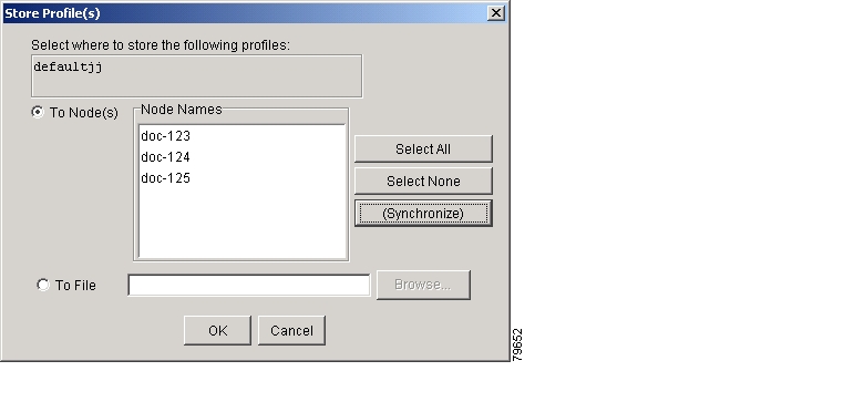
Step 15
Figure 22-3 Store Profiles Dialog Box
a.
•
•
•
•
b.
•
•
•
•
Step 16
•
•
•
Step 17
DLP-A519 Apply Alarm Profiles to Ports
Purpose
This task applies a custom or default alarm severity profile to a port or ports.
Tools/Equipment
None
Prerequisite Procedures
A518 Create a New or Cloned Alarm Severity Profile
Required/As Needed
As needed
Onsite/Remote
Onsite or remote
Security Level
Provisioning or higher
Step 1
Note
Note
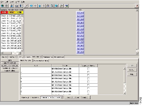
Step 2
Figure 22-4 shows the alarm profiles of DS1/E1-56 card ports. CTC shows Parent Card Profile: Inherited.
Figure 22-4 DS1-N-14 Card Alarm Behavior Tab
Go to Step 3 to apply profiles to a port. Go to Step 4 to apply profiles to all ports on a card.
Step 3
a.
b.
c.
Step 4
a.
b.
c.
d.
In node view the Port Level Profiles column indicates port-level profiles with a notation such as "exist (1)" ( Figure 18-3).
Step 5
Step 6
DLP-A520 Delete Alarm Severity Profiles
Step 1
Step 2
Step 3
Step 4
Step 5
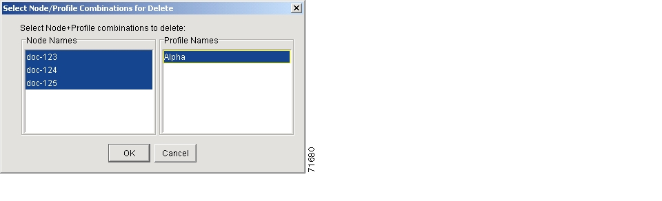
The Select Node/Profile Combination for Delete dialog box appears ( Figure 22-5).
Figure 22-5 Select Node/Profile Combination For Delete Dialog Box
Note
Note
Step 6
Tip
Step 7
Step 8
Click Yes in the Delete Alarm Profile dialog box.
Note
Provisioning > Alarm Profile Editor window unless you remove it using the following step.Step 9
Note
Note
Step 10
DLP-A521 Modify Alarm, Condition, and History Filtering Parameters
Purpose
This task changes alarm and condition reporting in all network nodes.
Tools/Equipment
None
Prerequisite Procedures
DLP-A225 Enable Alarm Filtering, page 19-17
Required/As Needed
As needed
Onsite/Remote
Onsite or remote
Security Level
Retrieve or higher
Step 1
Step 2
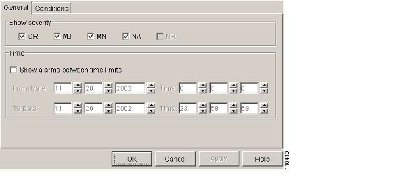
The filter dialog box appears, displaying the General tab. Figure 22-6 shows the Alarm Filter dialog box; the Conditions and History tabs have similar dialog boxes.
Figure 22-6 Alarm Filter Dialog Box General Tab
In the General tab Show Severity box, you can choose which alarm severities will show through the alarm filter and provision a time period during which filtered alarms show through the filter. To change the alarm severities shown in the filter, go to Step 3. To change the time period filter for the alarms go to Step 4.
Step 3
When alarm filtering is disabled, all alarms show.
Step 4
To modify filter parameters for conditions, continue with Step 5. If you do not need to modify them, continue with Step 6.
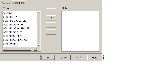
Step 5
Figure 22-7 Alarm Filter Dialog Box Conditions Tab
When filtering is enabled, conditions in the Show list are visible and conditions in the Hide list are invisible.
•
•
•
•
Note
Step 6
Alarm and condition filtering parameters are enforced when alarm filtering is enabled (see the "DLP-A225 Enable Alarm Filtering" task on page 19-17), and the parameters are not enforced when alarm filtering is disabled (see the "DLP-A227 Disable Alarm Filtering" task on page 19-18).
Step 7
DLP-A522 Suppress Alarm Reporting
Caution
Note
Step 1
Step 2
a.
b.
All raised alarms for the node will change color to white in the Alarms window and their status will change to cleared. After suppressing alarms, clicking Synchronize in the Alarms window will remove cleared alarms from the window. However, an AS-CMD alarm will show in node or card view to indicate that node-level alarms were suppressed, and the word System will appear in the Object column.
Note
Step 3
a.
b.
Alarms that directly apply to this card will change appearance as described in Step 2. For example, if you suppressed raised alarms for an OC-48 card in Slot 16, raised alarms for this card will change in node or card view. The AS-CMD alarm will show the slot number in the Object number. For example, if you suppressed alarms for a Slot 16 OC-48 card, the AS-CMD object will be "SLOT-16."
Click Apply.
Step 4
Step 5
Step 6
Step 7
Alarms that apply directly to this port will change appearance as described in Step 2. (However, alarms raised on the entire card will remain raised.) A raised AS-CMD alarm that shows the port as its object will appear in either alarm window. For example, if you suppressed alarms for Port 1 on the Slot 16 OC-48 card, the alarm object will show "FAC-16-1."
Step 8
DLP-A523 Discontinue Alarm Suppression
Caution
Step 1
a.
b.
Suppressed alarms will reappear in the Alarms window. (They might have previously been cleared from the window using the Synchronize button.) The AS-CMD alarm with the System object will be cleared in all views.
Step 2
a.
b.
c.
d.
Suppressed alarms will reappear in the Alarms window. (They might have previously been cleared from the window using the Synchronize button.) The AS-CMD alarm with the slot object (for example, SLOT-16) will be cleared in all views.
Step 3
Step 4
Step 5
Suppressed alarms will reappear in the Alarms window. (They might have previously been cleared from the window using the Synchronize button.) The AS-CMD alarm with the port object (for example, FAC-16-1) will be cleared in all views.
Step 6
DLP-A524 Download an Alarm Severity Profile
Step 1
Step 2
Step 3
Step 4
Step 5
a.
b.
Step 6
a.
b.
c.
Note
Note
Step 7
The downloaded profile appears at the right side of the Alarm Profiles window.
Step 8
Step 9
Step 10
a.
–
–
–
–
b.
Step 11
DLP-A526 Change Line and Threshold Settings for the DS3i-N-12 Cards
Note
Step 1
Step 2
Step 3
Note
Note
Step 4
Step 5
Step 6
For definitions of the line settings, see Table 22-1. For definitions of the line threshold settings, see Table 22-2. For definitions of the electrical path threshold settings, see Table 22-3. For definitions of the SONET threshold settings, see Table 22-4.
Table 22-1 describes the values on the Provisioning > Line tabs for the DS3i-N-12 cards.
Table 22-1 Line Options for the DS3i-N-12 Cards
Port
(Display only) Port number.
1 to 12
Port Name
Sets the port name.
User-defined, up to 32 alphanumeric/ special characters. Blank by default.
See the "DLP-A314 Assign a Name to a Port" task on page 20-8.
SF BER
Sets the signal fail bit error rate.
•
•
•
SD BER
Sets the signal degrade bit error rate.
•
•
•
•
•
Line Type
Defines the line framing type.
•
•
•
•
Detected Line Type
Displays the detected line type.
•
•
•
•
Line Coding
(Display only) Defines the DS3E transmission coding type.
B3ZS
Line Length
Defines the distance (in feet) from backplane connection to the next termination point.
•
•
Admin State
Sets the port administrative service state unless network conditions prevent the change.
•
•
•
•
Note
Service State
(Display only) Identifies the autonomously generated state that gives the overall condition of the port. Service states appear in the format: Primary State-Primary State Qualifier, Secondary State.
•
•
•
•
AINS Soak
Sets the automatic in-service soak period.
•
•
Table 22-2 describes the parameters on the Provisioning > Line Thresholds tabs for the DS3i-N-12 cards.
Table 22-3 describes the parameters on the Provisioning > Elect Path Thresholds tabs for the DS3i-N-12 cards.
Table 22-4 describes the values on the Provisioning > SONET Thresholds tabs for the DS3i-N-12 cards.
Note
Step 7
DLP-A527 Change the OC-N Card ALS Maintenance Settings
Note
Step 1
Step 2
Step 3
Step 4
Step 5
DLP-A528 Change the Default Network View Background Map
Note
Step 1
Step 2
Step 3
Step 4
Step 5
Step 6
Step 7
Step 8
Step 9
Step 10
DLP-A529 Delete Ethernet RMON Alarm Thresholds
Purpose
This task deletes remote monitoring (RMON) threshold crossing alarms for Ethernet ports.
Tools/Equipment
None
Prerequisite Procedures
A533 Create Ethernet RMON Alarm Thresholds
Required/As Needed
As needed
Onsite/Remote
Onsite or remote
Security Level
Provisioning or higher
Note
Step 1
Step 2
Note
Step 3
Step 4
Step 5
Step 6
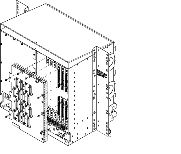
DLP-A530 Install the Tie-Down Bar
Purpose
This task installs the tie-down bar used to secure cabling on the rear of the ONS 15454. The tie-down bar can be used to provide a diverse path for redundant power feeds and cables.
Tools/Equipment
Tie-down bar
Screws (4)
Prerequisite Procedures
DLP-A5 Mount the Shelf Assembly in a Rack (One Person), page 17-5
DLP-A6 Mount the Shelf Assembly in a Rack (Two People), page 17-6
Required/As Needed
As needed
Onsite/Remote
Onsite
Security Level
None
Step 1
Figure 22-8 shows the tie-down bar, the ONS 15454, and the rack.
Figure 22-8 Tie-Down Bar
Step 2
Step 3
DLP-A531 Print CTC Data
Step 1
The print operation is available for all network, node, and card view windows.
Step 2
Step 3
•
•
•
–
–
–
–
–
–
–
–
–
–
–
–
–
–
–
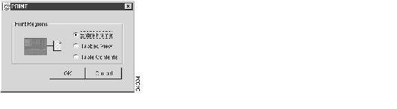
The Table Contents option prints all the data contained in a table and the table column headings. For example, if you print the History window Table Contents view, you print all data included in the table whether or not items appear in the window.
Tip
Figure 22-9 Selecting CTC Data For Print
Step 4
Step 5
Step 6
Step 7
DLP-A532 Export CTC Data
Step 1
Step 2
a.
b.
Step 3
Step 4
•
•
•
Figure 22-10 Selecting CTC Data For Export
Step 5
Text editor and word processor applications format the data exactly as it is exported, including comma or tab separators. All applications that open the data files allow you to format the data.
Step 6
Spreadsheet and database management programs also allow you to manage the exported data.
Note
The export operation does not apply to the following windows:
•
•
•
•
•
•
•
•
•
•
•
•
•
•
•
Step 7
Step 8
•
•
•
Step 9
Step 10
Step 11
Step 12
DLP-A533 Create Ethernet RMON Alarm Thresholds
Note
Step 1
Step 2
Step 3
Note
Step 4
The Create Ether Threshold dialog box appears ( Figure 22-11).
Figure 22-11 Creating RMON Thresholds
Step 5
Step 6
Step 7
Step 8
Step 9
Step 10
For a rising type of alarm, the measured value must move from below the falling threshold to above the rising threshold. For example, if a network is running below a rising threshold of 1000 collisions every 15 seconds and a problem causes 1001 collisions in 15 seconds, the excess occurrences trigger an alarm.
Step 11
A falling threshold is the counterpart to a rising threshold. When the number of occurrences is above the rising threshold and then drops below a falling threshold, it resets the rising threshold. For example, when the network problem that caused 1001 collisions in 15 minutes subsides and creates only 799 collisions in 15 minutes, occurrences fall below a falling threshold of 800 collisions. This resets the rising threshold so that if network collisions again spike over a 1000 per 15-minute period, an event again triggers when the rising threshold is crossed. An event is triggered only the first time a rising threshold is exceeded (otherwise, a single network problem might cause a rising threshold to be exceeded multiple times and cause a flood of events).
Step 12
Step 13
DLP-A534 Provision OSI Routing Mode
Caution
Caution
Caution
Note
Step 1
Step 2
Step 3
•
Note
•
•
–
–
Step 4
•
•
Step 5
DLP-A535 Provision or Modify TARP Operating Parameters
Step 1
Step 2
•
Note
•
Note
•
–
–
–
Note
•
Note
•
The TARP Data Cache parameter is designed for Intermediate System Level 1/Level 2 nodes that are connected to other Intermediate System Level 1/Level 2 nodes. Enabling the parameter for Intermediate System Level 1 nodes is not recommended.
•
The LDP parameter is not used if the Node Routing Mode is provisioned to End System or if the TARP PDUs L1 Propagation parameter is not enabled.
•
•
•
Note
•
•
•
•
•
•
Note
Step 3
Step 4
DLP-A536 Add a Static TID to NSAP Entry to the TARP Data Cache
Step 1
Step 2
Step 3
•
•
Step 4
Step 5
DLP-A537 Remove a Static TID to NSAP Entry from the TARP Data Cache
Step 1
Step 2
Step 3
Step 4
Step 5
DLP-A538 Add a TARP Manual Adjacency Table Entry
Step 1
Step 2
Step 3
•
–
–
•
Step 4
Step 5
DLP-A539 Provision OSI Routers
Note
Note
Note
Step 1
Step 2
Step 3
a.
b.
c.
d.
Step 4
DLP-A540 Provision Additional Manual Area Addresses
Step 1
Step 2
Step 3
a.
b.
c.
d.
Step 4
DLP-A541 Enable the OSI Subnet on the LAN Interface
Note
Note
Note
Step 1
Step 2
Step 3
•
•
•
•
•
Step 4
Step 5
DLP-A542 Create an IP-Over-CLNS Tunnel
Caution
Step 1
Step 2
Step 3
•
–
–
The Cisco proprietary tunnel is slightly more efficient than the GRE tunnel because it does not add the GRE header to each IP packet. The two tunnel types are not compatible. Most Cisco routers support the Cisco IP tunnel, while only a few support both GRE and Cisco IP tunnels. You generally should create Cisco IP tunnels if you are tunneling between two Cisco routers or between a Cisco router and an ONS node.
Caution
•
•
•
•
Step 4
Step 5
Step 6
DLP-A543 Remove a TARP Manual Adjacency Table Entry
Caution
Step 1
Step 2
Step 3
Step 4
Step 5
DLP-A544 Change the OSI Routing Mode
Purpose
This task changes the OSI routing mode.
Tools/Equipment
None
Prerequisite procedures
Required/As needed
As needed
Onsite/Remote
Onsite or remote
Security Level
Provisioning or higher
Caution
Caution
Caution
Step 1
•
•
•
Step 2
Step 3
•
•
–
–
Note
Step 4
•
•
Step 5
DLP-A545 Edit the OSI Router Configuration
Step 1
Step 2
Step 3
a.
Note
b.
c.
d.
Step 4
DLP-A546 Edit the OSI Subnetwork Point of Attachment
Step 1
Step 2
Step 3
•
•
•
Note
Click OK.
Step 4
DLP-A547 Edit an IP-Over-CLNS Tunnel
Purpose
This task allows you to edit the parameters of an IP-over-CLNS tunnel.
Tools/Equipment
None
Prerequisite procedures
A542 Create an IP-Over-CLNS Tunnel
Required/As needed
As needed
Onsite/Remote
Onsite or remote
Security Level
Provisioning or higher
Caution
Step 1
Step 2
Step 3
•
–
–
The Cisco proprietary tunnel is slightly more efficient than the GRE tunnel because it does not add the GRE header to each IP packet. The two tunnel types are not compatible. Most Cisco routers support the Cisco IP tunnel, while only a few support both GRE and Cisco IP tunnels. You generally should create Cisco IP tunnels if you are tunneling between two Cisco routers or between a Cisco router and an ONS node.
Caution
•
•
•
•
Step 4
Step 5
DLP-A548 Delete an IP-Over-CLNS Tunnel
Caution
Step 1
Step 2
Step 3
Step 4
Step 5
DLP-A549 View IS-IS Routing Information Base
Step 1
Step 2
•
•
•
•
Step 3
Step 4
DLP-A550 View ES-IS Routing Information Base
Step 1
Step 2
•
•
•
•
Step 3
Step 4
DLP-A551 Manage the TARP Data Cache
Step 1
Step 2
•
•
•
–
–
Step 3
Note
a.
b.
c.
d.
If TARP finds the TID in its TDC it returns the matching NSAP. If not, TARP sends PDUs across the network. Replies will return to the TDC later, and a check TDC later message is displayed.
Step 4
Step 5
DLP-A552 Adjust the Java Virtual Memory Heap Size
Step 1
Step 2
Step 3
Step 4
Step 5
Step 6
Step 7
Step 8
Step 9
Step 10
DLP-A553 Upgrade DS1 or DS3-12 Cards in a 1:N or 1:1 Configuration to High-Density Electrical Cards
Note
Step 1
Step 2
Step 3
Note
The following limitations apply if you are upgrading a low-density protect card:
•
•
•
•
•
The following limitations apply to upgrading a working card after you have upgraded the protect card:
•
•
Step 4
Step 5
a.
b.
Step 6
a.
b.
Step 7
a.
b.
Step 8
a.
b.
c.
Step 9
a.
b.
c.
Wait for the IMPROPRMVL alarm to clear and the card to become standby. For more information about LED behavior during the high-density card boot-up, see the "NTP-A17 Install the Electrical Cards" procedure on page 2-9.
Step 10
a.
b.
c.
d.
e.
Step 11
a.
a.
Step 12
a.
b.
c.
Step 13
a.
b.
c.
Wait for the IMPROPRMVL alarm to clear and the card to become standby. For more information about LED behavior during high-density electrical card bootup, see the "NTP-A17 Install the Electrical Cards" procedure on page 2-9.
Step 14
a.
b.
c.
d.
e.
Step 15
If you are using 735A cables, you must set the LBO for Ports 13 to 48 (DS3/EC1-48), doing so according to the following conventions:
Actual distance from the DSX panel is less than 110 feet (33.53 m):
LBO setting is " 0 - 225."
Actual distance from the DSX panel is greater than or equal to 110 feet (33.53 m):
LBO setting is "226 to 450."
If you have upgraded to a DS1/E1-56 card with UBIC EIAs, you must set the LBO for Ports 15 to 56, doing so according to the actual distance (in feet) from the LBX panel. Repeat Steps 4 through 14 for any other low-density cards you want to upgrade to high-density cards.
Step 16
DLP-A553 Upgrade DS3XM-6 Cards in a 1:1 Configuration to High-Density DS3XM-12 Electrical Cards
Note
Caution
Step 1
Step 2
Step 3
Note
The following limitations apply if you are upgrading a low-density protect card:
•
•
The following limitations apply to upgrading a working card after you have upgraded the protect card:
•
•
Step 4
Step 5
a.
b.
Step 6
a.
b.
Step 7
a.
b.
Step 8
a.
b.
c.
Step 9
a.
b.
c.
Wait for the IMPROPRMVL alarm to clear and the card to become standby. For more information about LED behavior during the high-density card boot-up, see the "NTP-A17 Install the Electrical Cards" procedure on page 2-9.
Step 10
a.
b.
c.
d.
e.
Step 11
a.
b.
Step 12
a.
b.
c.
Step 13
a.
b.
c.
Wait for the IMPROPRMVL alarm to clear and the card to become standby. For more information about LED behavior during high-density electrical card bootup, see the "NTP-A17 Install the Electrical Cards" procedure on page 2-9.
Step 14
a.
b.
c.
d.
The protect card should now become standby.
Note
If you want to create 1:N on DS3XM-12 cards only slot numbers 3 and 15 should be listed for protect card selection.
Step 15
If you are using 735A cables, you must set the LBO for Ports 7 to 12 (DS3XM-12doing so according to the following conventions:
Actual distance from the DSX panel is less than 110 feet (33.53 m):
LBO setting is " 0 - 225."
Actual distance from the DSX panel is greater than or equal to 110 feet (33.53 m):
LBO setting is "226 to 450."
Step 16 Return to your originating procedure (NTP).
DLP-A554 Upgrade EC-1 Cards in a 1:1 Configuration to DS3/EC1-48 Cards
Note
Caution
Step 1
Step 2
Step 3
Note
The following limitations apply if you are upgrading a low-density protect card:
•
•
Step 4
Slot 1 contains the protect card if you are working on the A side of the shelf, and Slot 17 contains the protect card if you are working on the B side of the shelf.
Step 5
a.
b.
Step 6
a.
b.
Step 7
a.
b.
c.
For more information about LED behavior during the high-density card boot-up, see the NTP-A17 Install the Electrical Cards, page 2-10. Allow the card to completely boot up before proceeding.
Step 8
a.
b.
Step 9
Note
Step 10
a.
b.
c.
d.
e.
Step 11
a.
b.
Step 12
a.
b.
c.
Step 13
a.
b.
c.
Wait for the IMPROPRMVL alarm to clear and the card to become standby. For more information about LED behavior during the high-density card bootup, see the NTP-A17 Install the Electrical Cards, page 2-10.
Step 14
a.
b.
c.
d.
The protect card in Slot 3 (A side) or Slot 15 (B side) should now become standby.
Note
If you are using 735A cables, you must set the LBO for Ports 13 to 48, doing so according to the following conventions:
Actual distance from the DSX panel is less than 110 feet (33.53 m):
LBO setting is " 0 - 225."
Actual distance from the DSX panel is greater than or equal to 110 feet (33.53 m):
LBO setting is "226 to 450."Step 15
Step 16
DLP-A555 Set Up SDH External or Line Timing
Step 1
Step 2
Step 3
Note
Step 4
•
Note
•
•
Step 5
Note
•
•
•
•
•
Step 6
The BITS Facilities section sets the parameters for your BITS1 and BITS2 timing references. Many of these settings are determined by the timing source manufacturer. If equipment is timed through BITS Out, you can set timing parameters to meet the requirements of the equipment.
Step 7
•
•
Step 8
•
•
•
•
•
Step 9
•
•
Step 10
•
•
•
•
Step 11
Note
Step 12
DLP-A556 Provision the Card Mode for ML-Series Ethernet Cards
Step 1
Step 2
Step 3
•
•
•
Note
Step 4
Step 5
DLP-A557 View Multirate PM Parameters
Step 1
Step 2
Step 3
Step 4
Step 5
Step 6
Step 7
DLP-A558 Provision the Designated SOCKS Servers
Note
Note
Note
Note
Step 1
Step 2
Step 3
Step 4
Step 5
Step 6
•
•
•
•
Step 7
Step 8
Step 9
DLP-A560 Create an Optimized 1+1 Protection Group
Step 1
Step 2
a.
b.
c.
Step 3
Step 4
Step 5
•
•
•
After you choose the protect card, a list of cards available for protection appear in the Available Ports list. If no cards are available, no cards appear. If this occurs, you cannot complete this task until you install the physical cards or preprovision the ONS 15454 slots using the "DLP-A330 Preprovision a Card Slot" task on page 20-20.
Step 6
Step 7
•
•
•
•
Step 8
Step 9
DLP-A561 Modify an Optimized 1+1 Protection Group
Purpose
This task modifies an optimized 1+1 protection group for OC3-4, OC3-8, and MRC-2.5G-4 cards (in OC-3 configurations).
Tools/Equipment
None
Prerequisite Procedures
A560 Create an Optimized 1+1 Protection Group
Required/As Needed
As needed
Onsite/Remote
Onsite or remote
Security Level
Provisioning or higher
Step 1
Step 2
Step 3
•
•
•
•
•
Step 4
Step 5
DLP-A562 View ML-Series RPR Span PM Parameters
Note
Step 1
Step 2
Step 3
Step 4
Note
Step 5
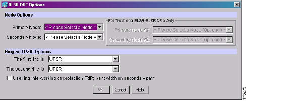
DLP-A563 Configure an Automatically Routed BLSR DRI
Purpose
This task enables you to set the primary and secondary nodes and ring and path options for an automatically routed BLSR Dual Ring Interconnect (DRI), as well as set circuit routing constraints.
Tools/Equipment
None
Prerequisite Procedures
DLP-A60 Log into CTC, page 17-62
You must check Dual Ring Interconnect on the Circuit Creation wizard during a circuit creation procedure (automatically routed).
Required/As Needed
As needed
Onsite/Remote
Onsite or remote
Security Level
Retrieve or higher
Step 1
Step 2
Step 3
•
•
•
•
Step 4
•
•
•
Figure 22-12 Selecting BLSR DRI Primary and Secondary Node Assignments
Step 5
Step 6
Step 7
Step 8
Step 9
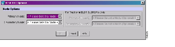
DLP-A564 Configure a Manually Routed BLSR DRI
Purpose
This task enables you to set the primary and secondary nodes for a manually routed BLSR DRI, as well as set circuit routing constraints.
Tools/Equipment
None
Prerequisite Procedures
DLP-A60 Log into CTC, page 17-62
You must check Dual Ring Interconnect on the Circuit Creation wizard during a circuit creation procedure (manually routed).
Required/As Needed
As needed
Onsite/Remote
Onsite or remote
Security Level
Retrieve or higher
Step 1
Step 2
Step 3
•
•
•
•
Step 4
Step 5
Step 6
Figure 22-13 Selecting BLSR DRI Primary and Secondary Node Assignments (Manual Routing)
Step 7
DLP-A565 Set Up a Solaris Workstation for a Craft Connection to an ONS 15454
Step 1
Step 2
# ifconfig device
For example:
# ifconfig hme1
If the interface is plumbed, a message similar to the following appears:
hme1:flags=1000842<BROADCAST,RUNNING,MULTICAST,IPv4>mtu 1500 index 2 inet 0.0.0.0
netmask 0
If a message similar to this one appears, go to Step 4.
If the interface is not plumbed, a message similar to the following appears:
ifconfig: status: SIOCGLIFFLAGS: hme1: no such interface.If a message similar to this one appears, go to Step 3.
Step 3
# ifconfig device plumb
For example:
# ifconfig hme1 plumb
Step 4
# ifconfig interface ip-address netmask netmask up
For example:
# ifconfig hme0 192.1.0.3 netmask 255.255.255.0 up
Note
Step 5
Step 6
a.
b.
c.
ping ONS-15454-IP-address
For example, to connect to an ONS 15454 with a default IP address of 192.1.0.2, type:
ping 192.1.0.2
If your workstation is connected to the ONS 15454, the following message appears:
IP-address is alive
Note
d.
# ndd -set /dev/device instance 0
# ndd -get /dev/device link_status
For example:
# ndd -set /dev/hme instance 0
# ndd -get /dev/hme link_status
A result of "1" means the link is up. A result of "0" means the link is down.
Note
#man ndd.Step 7
DLP-A566 Install the CTC Launcher Application from a Release 8.0 Software CD
Step 1
Step 2
Step 3
Step 4
DLP-A567 Install the CTC Launcher Application from a Release 8.0 Node
Step 1
http://<node-name>/fs/StartCTC.exeThe browser File Download window opens.
Step 2
Step 3
Step 4
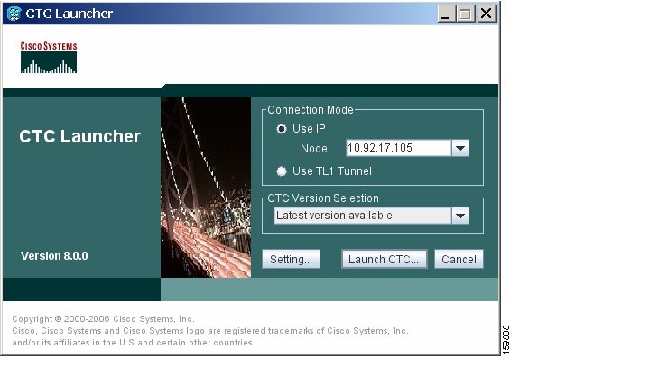
DLP-A568 Connect to ONS Nodes Using the CTC Launcher
Purpose
This task connects the CTC Launcher to ONS nodes.
Tools/Equipment
None
Prerequisite Procedures
Required/As Needed
As needed
Onsite/Remote
Onsite or remote
Security Level
None
Step 1
•
•
% java -jar StartCTC.exe
Step 2
Figure 22-14 shows the CTC Launcher window.
Figure 22-14 CTC Launcher Window
Step 3
Step 4
•
•
•
Note
Step 5
Step 6
Note
After the JRE version is selected, the CTC will be launched. The required jar files will be downloaded into the new cache if they are missing. The CTC Login window will appear after a few seconds.Step 7
DLP-A569 Create a TL1 Tunnel Using the CTC Launcher
Step 1
Step 2
Step 3
•
•
•
–
–
•
–
–
–
•
•
Step 4
Step 5
a.
b.
c.
Step 6
Step 7
DLP-A570 Create a TL1 Tunnel Using CTC
Purpose
This task creates a TL1 tunnel using CTC.
Tools/Equipment
None
Prerequisite Procedures
Required/As Needed
As needed
Onsite/Remote
Onsite or remote
Security Level
Provisioning or higher
Step 1
Step 2
Step 3
•
•
•
–
–
•
–
–
–
•
•
Step 4
Step 5
a.
b.
c.
Step 6
Step 7
DLP-A571 View TL1 Tunnel Information
Step 1
Step 2
Step 3
Step 4
DLP-A572 Edit a TL1 Tunnel Using CTC
Purpose
This task edits a TL1 tunnel using CTC.
Tools/Equipment
None
Prerequisite Procedures
Required/As Needed
As needed
Onsite/Remote
Onsite or remote
Security Level
Provisioning or higher
Step 1
Step 2
Step 3
Step 4
•
•
•
–
–
–
•
•
Step 5
Step 6
a.
b.
c.
Step 7
Step 8
DLP-A573 Delete a TL1 Tunnel Using CTC
Purpose
This task deletes a TL1 tunnel using CTC.
Tools/Equipment
None
Prerequisite Procedures
Required/As Needed
As needed
Onsite/Remote
Onsite or remote
Security Level
Provisioning or higher
Step 1
Step 2
Step 3
Step 4
Step 5
DLP-A574 Provision a PPM on the MRC-12 or MRC-2.5G-4 Card
Step 1
Step 2
Step 3
Step 4
•
•
Step 5
Step 6
Step 7
Step 8
Step 9
Step 10
DLP-A575 Provision the Optical Line Rate on the MRC-12 or MRC-2.5G-4 Card
Step 1
Step 2
Step 3
Step 4
•
•
Table 22-9 PPM Port Types
MRC-12 and MRC-2.5G-4
•
•
•
Step 5
Step 6
Step 7
Step 8
DLP-A576 Change the Optical Line Rate on the MRC-12 or MRC-2.5G-4 Card
Step 1
Step 2
Step 3
Step 4
Step 5
Step 6
Step 7
DLP-A577 Delete a PPM from the MRC-12, MRC-2.5G-4, or OC192-XFP Card
Step 1
You cannot delete a port on a PPM if it is in service, part of a protection group, has a communications channel termination in use, is used as a timing source, has circuits, or has overhead circuits. As needed, complete the following procedures and task:
•
•
•
•
•
Step 2
Step 3
Step 4
a.
b.
c.
Step 5
•
•
Step 6
Step 7
![]()
![]()
![]()
![]()
![]()
![]()
![]()
![]()
Posted: Mon Nov 12 00:33:03 PST 2007
All contents are Copyright © 1992--2007 Cisco Systems, Inc. All rights reserved.
Important Notices and Privacy Statement.