|
|

Table Of Contents
Install the Shelf and Backplane Cable
NTP-1 Unpack and Inspect the ONS 15454 Shelf Assembly
DLP-1 Unpack and Verify the Shelf Assembly
DLP-2 Inspect the Shelf Assembly
NTP-2 Install the Shelf Assembly
DLP-3 Reverse the Mounting Bracket to Fit a 19-inch Rack
DLP-4 Install the External Brackets and Air Filter
DLP-5 Mount the Shelf Assembly in a Rack (One Person)
DLP-6 Mount the Shelf Assembly in a Rack (Two People)
DLP-7 Mount Multiple Shelf Assemblies in a Rack
NTP-3 Open and Remove the Front Door
DLP-8 Open the Front Cabinet Compartment (Door)
NTP-4 Remove the Backplane Covers
DLP-10 Remove the Lower Backplane Cover
DLP-11 Remove the Backplane Sheet Metal Cover
NTP-5 Install the Electrical Interface Assemblies
DLP-12 Install a BNC or High-Density BNC EIA
DLP-14 Install the AMP Champ EIA
NTP-6 Install the Power and Ground
DLP-15 Verify that the Correct Fuse and Alarm Panel is Installed in the Equipment Rack
DLP-16 Connect the Office Ground to the ONS 15454
DLP-17 Connect Office Power to the ONS 15454 Shelf
DLP-18 Turn On and Verify Office Power
NTP-7 Install the Fan-Tray Assembly
NTP-119 Install the Alarm Expansion Panel
NTP-8 Install Wires to Alarm, Timing, LAN, and Craft Pin Connections
DLP-19 Install Alarm Wires on the Backplane
DLP-20 Install Timing Wires on the Backplane
DLP-21 Install LAN Wires on the Backplane
DLP-22 Install the TL1 Craft Interface
NTP-120 Install an External Wire-Wrap Panel to the AEP
NTP-9 Install the Electrical Card Cables on the Backplane
DLP-23 Install DS-1 Cables Using Electrical Interface Adapters (Balun)
DLP-24 Install DS-1 AMP Champ Cables on the AMP Champ EIA
DLP-25 Install Coaxial Cable With BNC Connectors
DLP-26 Install Coaxial Cable With High-Density BNC Connectors
DLP-27 Install Coaxial Cable with SMB Connectors
NTP-10 Route Electrical Cables
DLP-29 Route DS-1 Twisted-Pair Cables
DLP-30 Install Ferrites to Power Cabling
DLP-31 Attach Ferrites to Wire-Wrap Pin Fields
NTP-13 Perform the Shelf Installation Acceptance Test
DLP-32 Inspect the Shelf Installation and Connections
Install the Shelf and Backplane Cable
This chapter provides procedures for installing the Cisco ONS 15454. To view a summary of the tools and equipment required for installation, see the "Required Tools and Equipment" section.
Before You Begin
This section lists the chapter procedures (NTPs). Turn to a procedure for applicable tasks (DLPs).
1.
NTP-1 Unpack and Inspect the ONS 15454 Shelf Assembly—Complete this procedure before continuing with the "NTP-2 Install the Shelf Assembly" procedure.
2.
3.
4.
5.
6.
7.
8.
9.
10.
11.
12.
13.
14.
15.
Warning
Warning
Warning
Required Tools and Equipment
You will need the following tools and equipment to install and test the ONS 15454.
Included Materials
The following materials are required and are shipped with the ONS 15454 shelf (wrapped in plastic). The number in parentheses gives the quantity of the item included in the package.
•
•
•
•
•
•
•
•
•
•
•
–
–
User-Supplied Materials
The following materials and tools are required but are not supplied with the ONS 15454.
•
•
•
Note
•
Note
•
•
•
•
•
•
•
•
•
#10 AWG copper conductorsTools Needed
•
•
•
•
•
•
•
•
Test Equipment
•
•
•
NTP-1 Unpack and Inspect the ONS 15454 Shelf Assembly
Step 1
Step 2
Step 3
DLP-1 Unpack and Verify the Shelf Assembly
Purpose
This task removes the shelf assembly from the package.
Tools/Equipment
None
Prerequisite Procedures
None
Required/As Needed
Required
Onsite/Remote
Onsite
Step 1
Step 2
Step 3
Step 4
Note
Step 5
DLP-2 Inspect the Shelf Assembly
Step 1
Step 2
•
•
Step 3
Step 4
Step 5
NTP-2 Install the Shelf Assembly
Warning
Note
Warning
Warning
Step 1
Step 2
Step 3
•
•
•
Step 4
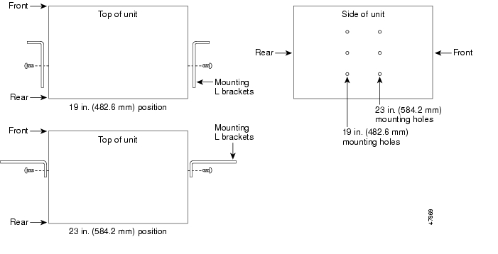
DLP-3 Reverse the Mounting Bracket to Fit a 19-inch Rack
Caution
Caution
Step 1
Step 2
Text imprinted on the mounting bracket will now also be upside down.
Step 3
The narrow side of the mounting bracket should be towards the front of the shelf assembly. Text imprinted on the mounting bracket should be visible and upside down.
Step 4
Step 5
Step 6
Figure 1-1 Reversing the mounting brackets (23-inch position to 19-inch position)
Step 7
DLP-4 Install the External Brackets and Air Filter
The shelf assembly ships with external (bottom) brackets that you can use to install the air filter on the bottom of the shelf rather than beneath the fan-tray assembly. The brackets consist of two grooved metal pieces that attach to the bottom of the shelf assembly using three screws each. When you use the brackets to install the fan-tray air filter, you do not need to remove the fan-tray assembly to access the air filter. Attach the brackets to the bottom of the shelf assembly before installing the rack.
Although the filter will work if it is installed with either side facing up, Cisco recommends that you install it with the metal bracing facing up to preserve the surface of the filter.
Purpose
This task installs the external brackets and air filter.
Tools/Equipment
#2 Phillips screwdriver
Medium slot head screwdriver
Small slot head screwdriver
Prerequisite Procedures
DLP-3 Reverse the Mounting Bracket to Fit a 19-inch Rack, if applicable
Required/As Needed
As needed; perform this task if you want to access the air filter without removing the fan-tray assembly.
Onsite/Remote
Onsite
Note
Step 1
Step 2
Step 3
Each bracket has a filter stopper and a flange on one end. Make sure to attach the brackets with the stoppers and flanges facing the rear of the shelf assembly (the top, if the ONS 15454 is face-down during installation).
Figure 1-2 illustrates bottom bracket installation. If you do not use the brackets, in the future you must remove the fan-tray assembly before removing the air filter. The brackets enable you to clean and replace the air filter without removing the fan-tray assembly.
Figure 1-2 Installing the external brackets
Step 4
Step 5
DLP-5 Mount the Shelf Assembly in a Rack (One Person)
Purpose
This task allows one person to mount the shelf assembly in a rack.
Tools/Equipment
Pinned hex key
Two set screws (48-1003-XX)
# 2 Phillips screwdriver
Prerequisite Procedures
DLP-3 Reverse the Mounting Bracket to Fit a 19-inch Rack, if applicable
DLP-4 Install the External Brackets and Air Filter, if applicable
Required/As Needed
As needed
Onsite/Remote
Onsite
Step 1
•
•
Step 2
Step 3
Step 4
Step 5
Step 6
Step 7
Note
Step 8
Step 9
DLP-6 Mount the Shelf Assembly in a Rack (Two People)
Purpose
This task allows two people to mount the shelf assembly in a rack.
Tools/Equipment
•
•
•
Prerequisite Procedures
DLP-3 Reverse the Mounting Bracket to Fit a 19-inch Rack, if applicable
DLP-4 Install the External Brackets and Air Filter, if applicable
Required/As Needed
Required
Onsite/Remote
Onsite
Step 1
•
•
Step 2
Step 3
Step 4
Step 5
Step 6
Step 7
Note
Step 8
Step 9
DLP-7 Mount Multiple Shelf Assemblies in a Rack
Purpose
This task allows multiple shelves to be assembled in a rack.
Tools/Equipment
#2 Phillips screwdriver
Medium slot head screwdriver
Small slot head screwdriver
Prerequisite Procedures
•
•
Required/As Needed
As needed
Onsite/Remote
Onsite
Note
Step 1
•
•
Step 2
Step 3
Step 4
NTP-3 Open and Remove the Front Door
Step 1
Step 2
Step 3
DLP-8 Open the Front Cabinet Compartment (Door)
Purpose
This task opens the front cabinet compartment door.
Tools/Equipment
Pinned hex key
Prerequisite Procedures
DLP-3 Reverse the Mounting Bracket to Fit a 19-inch Rack, if applicable
DLP-4 Install the External Brackets and Air Filter, if applicable
DLP-5 Mount the Shelf Assembly in a Rack (One Person) or DLP-6 Mount the Shelf Assembly in a Rack (Two People)
DLP-7 Mount Multiple Shelf Assemblies in a Rack, if applicable
Required/As Needed
Required
Onsite/Remote
Onsite
Note
Step 1
The ONS 15454 comes with a pinned hex key for locking and unlocking the front door. Turn the key counterclockwise to unlock the door and clockwise to lock it.
Step 2
Step 3
Figure 1-3 The ONS 15454 front door
Step 4
DLP-9 Remove the Front Door
Purpose
This task removes the front cabinet compartment door.
Tools/Equipment
Open end wrench
Prerequisite Procedures
Required/As Needed
Required
Onsite/Remote
Onsite
Step 1
Step 2
a.
b.
Step 3
Figure 1-4 Removing the ONS 15454 front door
Step 4
NTP-4 Remove the Backplane Covers
Step 1
Step 2
Step 3
DLP-10 Remove the Lower Backplane Cover
Purpose
This task removes the lower backplane cover.
Tools/Equipment
#2 Phillips screwdriver
Medium slot head screwdriver
Small slot head screwdriver
Prerequisite Procedures
•
•
•
•
Required/As Needed
Required
Onsite/Remote
Onsite
Step 1
Step 2
Step 3
Step 4
DLP-11 Remove the Backplane Sheet Metal Cover
Purpose
This task removes the backplane sheet cover that is installed on the backplane when EIAs are not installed.
Tools/Equipment
#2 Phillips screwdriver
Medium slot head screwdriver
Small slot head screwdriver
Prerequisite Procedures
DLP-3 Reverse the Mounting Bracket to Fit a 19-inch Rack, if applicable
DLP-4 Install the External Brackets and Air Filter, if applicable
DLP-5 Mount the Shelf Assembly in a Rack (One Person) or DLP-6 Mount the Shelf Assembly in a Rack (Two People)
DLP-7 Mount Multiple Shelf Assemblies in a Rack, if applicable
Required/As Needed
Required
Onsite/Remote
Onsite
Step 1
Step 2
Step 3
Step 4
Step 5
NTP-5 Install the Electrical Interface Assemblies
Caution
Note
Step 1
Step 2
Step 3
Note
Step 4
DLP-12 Install a BNC or High-Density BNC EIA
Step 1
Step 2
Step 3
Step 4
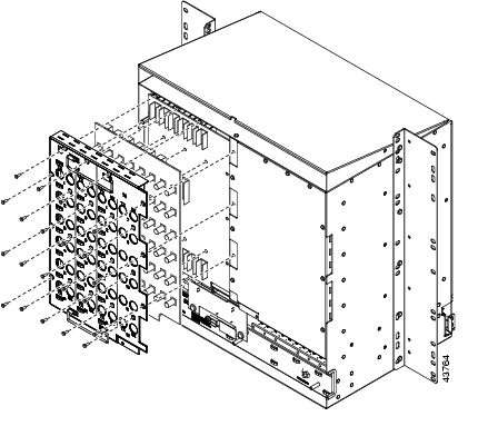
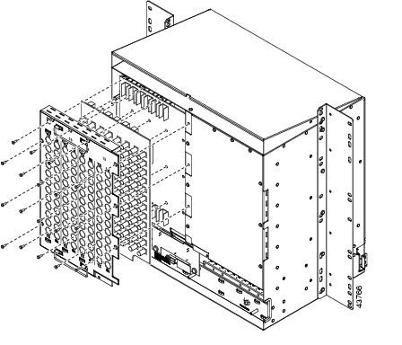
Figure 1-5 shows a BNC EIA installation. Figure 1-6 shows high-density BNC EIA installation.
Figure 1-5 Installing the BNC EIA
Figure 1-6 Installing the high-density BNC EIA
Step 5
DLP-13 Install an SMB EIA
Step 1
Step 2
Step 3
Step 4
If you are using SMB EIAs to make DS-1 connections, you need the DS-1 electrical interface adapter, commonly referred to as a balun (P/N 15454-WW-14=).
Step 5
DLP-14 Install the AMP Champ EIA
Step 1
Step 2
Step 3
Step 4
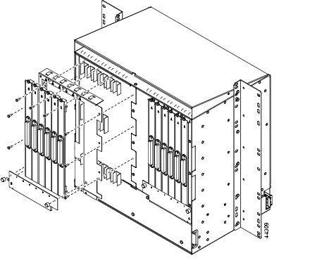
Figure 1-7 shows an AMP Champ EIA installation.
Figure 1-7 Installing the AMP Champ EIA
Step 5
NTP-6 Install the Power and Ground
Warning
Warning
Caution
Warning
Warning
Warning
Warning
Warning
Warning
Step 1
Step 2
Step 3
Step 4
Step 5
DLP-15 Verify that the Correct Fuse and Alarm Panel is Installed in the Equipment Rack
Purpose
This task verifies that the proper fuse and alarm panel is installed in the equipment rack.
Tools/Equipment
None
Prerequisite Procedures
None
Required/As Needed
Required
Onsite/Remote
Onsite
Step 1
•
•
Step 2
DLP-16 Connect the Office Ground to the ONS 15454
Step 1
Step 2
Note
Figure 1-8 Ground location on the backplane
Step 3
Step 4
DLP-17 Connect Office Power to the ONS 15454 Shelf
Purpose
This task connects power to the ONS 15454 shelf.
Tools/Equipment
#2 Phillips screwdriver
Medium slot head screwdriver
Small slot head screwdriver
Wire wrapper
Wire cutters
Wire strippers
Crimp tool
Fuse panel
Power cable (from fuse and alarm panel to assembly), #10 AWG, copper conductors, 194ΑF [90ΑC])
Ground cable #6 AWG stranded
Listed pressure terminal connectors such as ring and fork types; connectors must be suitable for #10 AWG copper conductors
Prerequisite Procedures
DLP-15 Verify that the Correct Fuse and Alarm Panel is Installed in the Equipment Rack
Required/As Needed
Required
Onsite/Remote
Onsite
Note
Note
Warning
Step 1
Step 2
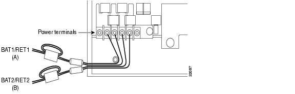
Step 3
Warning
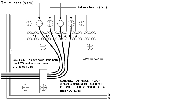
Figure 1-9 ONS 15454 power terminals
Step 4
Note
Caution
Caution
Step 5
Step 6
Note
Step 7
Warning
Step 8
Step 9
Step 10
Step 11
DLP-18 Turn On and Verify Office Power
Purpose
This task measures the power to verify correct power and returns.
Tools/Equipment
Voltmeter
Prerequisite Procedures
DLP-15 Verify that the Correct Fuse and Alarm Panel is Installed in the Equipment Rack
DLP-16 Connect the Office Ground to the ONS 15454
Required/As Needed
Required
Onsite/Remote
Onsite
Step 1
a.
Note
b.
Step 2
•
•
Step 3
a.
Note
b.
Step 4
NTP-7 Install the Fan-Tray Assembly
Purpose
This procedure installs the fan-tray assembly.
Tools/Equipment
#2 Phillips screwdriver
Medium slot head screwdriver
Small slot head screwdriver
Prerequisite Procedures
NTP-3 Open and Remove the Front Door
Required/As Needed
Required
Onsite/Remote
Onsite
Caution
Caution
Caution
Caution
Note
Step 1
Step 2
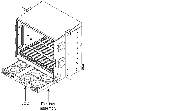
Figure 1-10 shows the location of the fan tray.
Figure 1-10 Installing the fan-tray assembly
Step 3
NTP-119 Install the Alarm Expansion Panel
Note
Step 1
Figure 1-11 Replace backplane screws with standoffs
Step 2
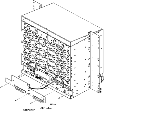
Step 3
Figure 1-12 Installing standoffs and the AEP
Step 4
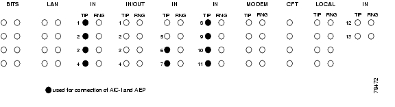
Step 5
Figure 1-13 AEP wire-wrap connections to backplane pins
Step 6
Step 7
NTP-8 Install Wires to Alarm, Timing, LAN, and Craft Pin Connections
Step 1
Step 2
Step 3
Step 4
Caution
Step 5
•
•
•
DLP-19 Install Alarm Wires on the Backplane
Step 1
Step 2
For information about attaching ferrites to wire-wrap pin fields, see the "NTP-12 Install Ferrites" section.
Figure 1-14 ONS 15454 backplane pinouts (Release 3.4)
Figure 1-15 ONS 15454 backplane pinouts (Release 3.3 and earlier)
Note
Step 3
DLP-20 Install Timing Wires on the Backplane
Step 1
Step 2
The BITS pin field (FG1) has a frame ground pin beneath it. Wrap the ground shield of the alarm cable to the frame ground pin. Table 1-2 lists the pin assignments for the BITS timing pin fields.
Note
Step 3
DLP-21 Install LAN Wires on the Backplane
Note
Step 1
Step 2
Caution
A frame ground pin is located beneath each pin field (FG2 for the LAN pin field). Wrap the ground shield of the LAN interface cable to the frame ground pin. Table 1-3 shows the LAN pin assignments.
Step 3
DLP-22 Install the TL1 Craft Interface
Note
Step 1
Step 2
Note
Step 3
Wrap the ground wire of your computer cable to pin A3 on the craft pin field. Table 1-4 shows the pin assignments for the CRAFT pin field.
Note
Table 1-4 Craft Interface Pin Assignments
Craft
A1
Receive
A2
Transmit
A3
Ground
A4
DTR
Step 4
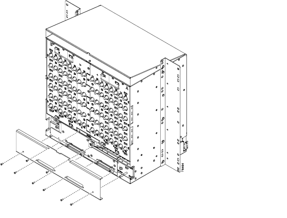
NTP-120 Install an External Wire-Wrap Panel to the AEP
Step 1
Figure 1-16 Installing the AEP cover
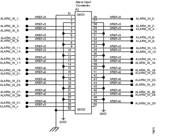
Step 2
Step 3
Figure 1-17 Alarm input connector
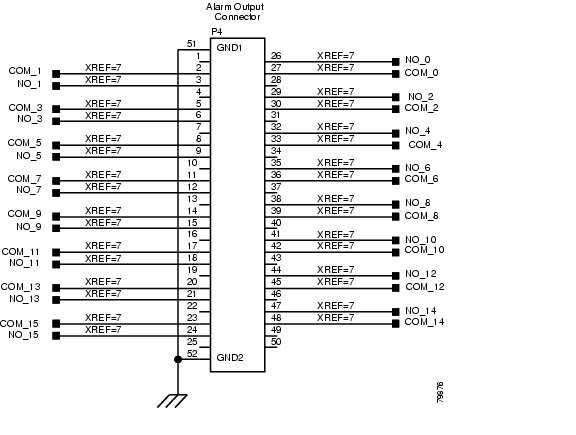
Figure 1-18 Alarm output connector
Step 4
•
•
NTP-9 Install the Electrical Card Cables on the Backplane
Caution
Note
Step 1
Step 2
Step 3
Step 4
Step 5
Step 6
DLP-23 Install DS-1 Cables Using Electrical Interface Adapters (Balun)
Note
Step 1
Step 2
Step 3
a.
b.
c.
Note
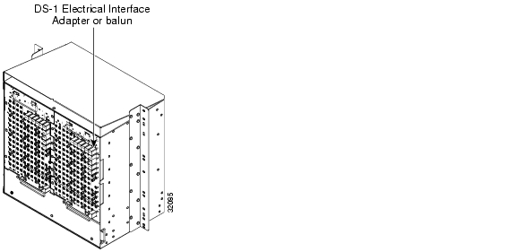
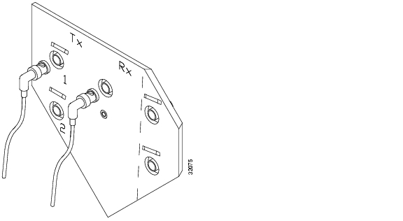
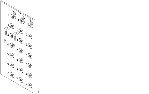
Figure 1-19 shows a ONS 15454 backplane with an SMB EIA with DS-1 electrical interface adapters attached on both sides of the shelf assembly to create DS-1 twisted-pair termination points.
Figure 1-19 A backplane with an SMB EIA for DS-1 cables
Step 4
DLP-24 Install DS-1 AMP Champ Cables on the AMP Champ EIA
Step 1
Step 2
Step 3
The female connector has grooves on the outside edge for snapping the clips into place.
Table 1-7 shows the pin assignments for the AMP Champ connectors on the ONS 15454 AMP Champ EIA. The shaded area corresponds to the white/orange binder group. A binder group is a set of 25 pairs of wires coded with an industry-standard color scheme.
Table 1-8 shows the pin assignments for the AMP Champ connectors on the ONS 15454 AMP Champ EIA for a shielded DS-1 cable.
Step 4
DLP-25 Install Coaxial Cable With BNC Connectors
Step 1
Figure 1-20 shows how to connect a coaxial cable to the BNC EIA using a right-angle BNC cable connector.
Figure 1-20 Using a right-angle connector to install coaxial cable with BNC connectors
Step 2
Step 3
Step 4
Step 5
Step 6
Warning
Step 7
Step 8
DLP-26 Install Coaxial Cable With High-Density BNC Connectors
Step 1
Step 2
Step 3
Step 4
Step 5
Step 6
Warning
The rubber coated edges of the side cutouts prevent the cables from chafing.
Step 7
DLP-27 Install Coaxial Cable with SMB Connectors
Purpose
This task installs the coaxial cable with SMB connectors. Refer to Figure 1-21 when performing task.
Tools/Equipment
SMB cable connector
Prerequisite Procedures
Required/As Needed
Required if you are using DS3-12, DS3XM-6, or EC-1 cards and are using an SMB interface rather than a BNC interface
Onsite/Remote
Onsite
Step 1
Step 2
Step 3
Step 4
Figure 1-21 Installing coaxial cable with SMB connectors
Warning
Step 5
Step 6
NTP-10 Route Electrical Cables
Step 1
Step 2
Step 3
DLP-28 Route Coaxial Cables
Purpose
This task routes the coaxial cables.
Tools/Equipment
RG179, RG59 (735A) 26 AWG cable, or RG59 (734A) 20 AWG cable
Prerequisite Procedures
DLP-25 Install Coaxial Cable With BNC Connectors
DLP-26 Install Coaxial Cable With High-Density BNC Connectors
Required/As Needed
Required
Onsite/Remote
Onsite
Step 1
Step 2
Step 3
When using the RG179 cable, the maximum distance available (122 feet) is less than the maximum distance available with standard RG59 (735A) cable (306 feet). The maximum distance when using the RG59 (734A) cable is 450 feet. The shorter maximum distance available with the RG179 is due to a higher attenuation rate for the thinner cable. Attenuation rates are calculated using a DS-3 signal:
•
•
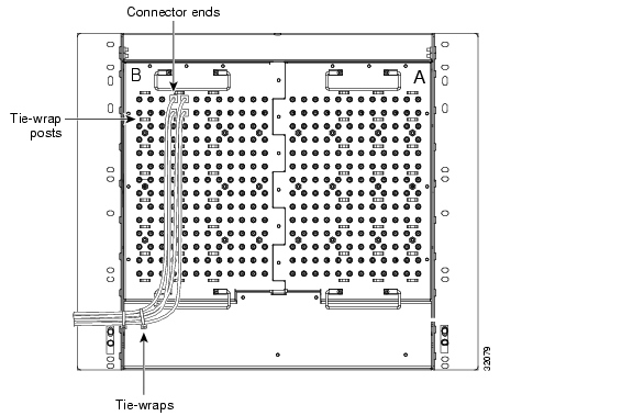
Use a figure of 5.0 for total cable loss when making calculations. Figure 1-22 shows an example of proper coaxial cable routing.
Figure 1-22 Routing coaxial cable (SMB EIA backplane)
Step 4
DLP-29 Route DS-1 Twisted-Pair Cables
Purpose
This task routes the DS-1 twisted-pair cables.
Tools/Equipment
None
Prerequisite Procedures
DLP-23 Install DS-1 Cables Using Electrical Interface Adapters (Balun)
Required/As Needed
Required
Onsite/Remote
Onsite
Step 1
•
•
Step 2
Note
Step 3
NTP-11 Install the Rear Cover
Step 1
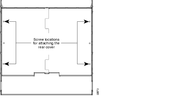
Figure 1-23 Backplane attachment for the rear cover
Tip
Step 2
Step 3
Step 4
Step 5
Figure 1-24 shows rear cover installation using spacers.
Figure 1-24 Installing the rear cover with spacers
Step 6
NTP-12 Install Ferrites
Purpose
This procedure describes how to attach ferrites.
Tools/Equipment
Oval and/or block ferrites
Prerequisite Procedures
NTP-6 Install the Power and Ground
NTP-8 Install Wires to Alarm, Timing, LAN, and Craft Pin Connections
Required/As Needed
As needed
Onsite/Remote
Onsite
Step 1
Step 2
Step 3
DLP-30 Install Ferrites to Power Cabling
Step 1
Step 2
Note
Note
Figure 1-25 Attaching block and oval ferrites to power cabling
Step 3
DLP-31 Attach Ferrites to Wire-Wrap Pin Fields
Purpose
This task attaches ferrites to wire-wrap pin fields. Use an oval ferrite TDK ZCAT1730-0730 and block ferrite Fair Rite 0443164151 for each pair of cables. Figure 1-26 shows the suggested method for attaching ferrites to wire-wrap pin fields.
Tools/Equipment
Oval and block ferrites
Prerequisite Procedures
NTP-8 Install Wires to Alarm, Timing, LAN, and Craft Pin Connections
Required/As Needed
As needed
Onsite/Remote
Onsite
Step 1
Step 2
Figure 1-26 Attaching ferrites to wire-wrap pin fields
Step 3
NTP-13 Perform the Shelf Installation Acceptance Test
Step 1
Table 1-9 ONS 15454 Shelf Installation Task Summary
NTP-8 Install Wires to Alarm, Timing, LAN, and Craft Pin Connections
Step 2
Step 3
Step 4
DLP-32 Inspect the Shelf Installation and Connections
Purpose
This task inspects the shelf installation and connections to verify everything is installed and connected properly.
Tools/Equipment
None
Prerequisite Procedures
Complete Table 1-9.
Required/As Needed
Required
Onsite/Remote
Onsite
Step 1
Step 2
Step 3
DLP-33 Measure Voltage
Purpose
This task measures the power to verify correct power and returns.
Tools/Equipment
Voltmeter
Prerequisite Procedures
Complete Table 1-9.
Required/As Needed
Required
Onsite/Remote
Onsite
Step 1
a.
Step b.b.
Step 2
a.
•
•
•
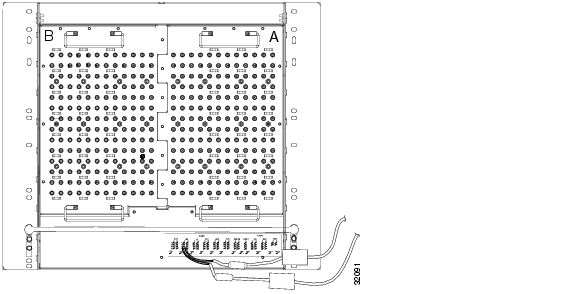
b.
Figure 1-27 ONS 15454 power terminals
Step 3
![]()
![]()
![]()
![]()
![]()
![]()
![]()
![]()
Posted: Fri Feb 22 14:34:12 PST 2008
All contents are Copyright © 1992--2008 Cisco Systems, Inc. All rights reserved.
Important Notices and Privacy Statement.