|
|

This chapter includes the following sections:
The Cisco 6700 series element management system (EMS) is a powerful operations and management tool with a graphical user interface. EMS enables users to provision, manage, and monitor up to 2,500 nodes within the network.
Table 1-1 describes some of the terms used throughout this EMS guide.
| Term | Definition |
|---|---|
Network element—The physical Cisco 6705, Cisco 6732, or Cisco IAD1101 chassis. | |
The EMS representation of an NE in the network (shown as an icon in the EMS NetView). | |
A space in the NE chassis used to house a card. | |
A modular element placed in a slot of the chassis. A card that provides one or more user traffic interfaces (lines) is called a line card; a card that does not offer user traffic interfaces is called a common card. | |
An interface designed to carry user traffic (data or voice) across the network. | |
An interface designed to carry nonuser traffic (such as management traffic) from the NE to a network device or workstation. |
Table 1-2 describes the different EMS windows (views). Each view is detailed in the sections that follow.
| View | Description | How to Open | How to Close |
|---|---|---|---|
NetView | A view of the network, using icons to represent installed nodes. Individual nodes are created and modified in NetView. | NetView appears when EMS is initially launched. | Select File > Exit from the menu bar. This closes EMS. |
A special display used to configure connections between nodes. | From NetView, click the Inter Node Provision button at the top right of the window. | Select File > Exit from the menu bar to return to NetView. | |
A graphic representation of a Cisco network element chassis, complete with installed cards. Lines and cards are provisioned from NodeView. | From NetView, double-click a node, or right-click a node and select NodeView from the popup menu. | Select File > Exit from the menu bar to return to NetView. | |
A window used to set important NE parameters such as IP address, timing source, and node ID. | From NodeView, double-click the node nameplate (located at the top of the screen). | Select Exit from the function bar to return to NodeView. | |
A window used to provision a slot for a particular card. | From NodeView, double-click any empty slot. | Select Exit from the function bar to return to NodeView. | |
A window used to set individual card settings. | From NodeView, double-click any card. | Select Exit from the function bar to return to NodeView. | |
A window used to set individual line settings and parameters. | From NodeView, double-click any line. | Select Exit from the function bar to return to NodeView. |
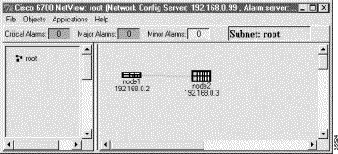
Cisco 6700 series NetView appears when EMS is initially launched and displays the topology of the network. (See Figure 1-1.) From NetView, all nodes, subnets, and end node lists can be created or modified. (See "NetView" for provisioning information.)
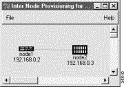
The inter node provisioning window is used to provision connections between two or more NEs. (See Figure 1-2.) By clicking the visual links drawn between nodes, you can create, modify, or delete internode connections. (See "Inter Node Data Link Procedure" for provisioning information.)
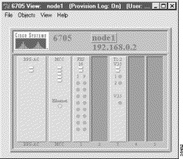
The EMS NodeView provides a graphical representation of an NE, complete with installed cards and LEDs. (See Figure 1-3, Figure 1-4, and Figure 1-5.) Use NodeView to provision all slots, cards, and lines in the NE. (See "Provisioning Slots" for provisioning information.)


The NE provision window is used to provision important NE parameters. To open the NE provision window, double-click the node nameplate in NodeView. (See Figure 1-6.) See "Initial Node Provisioning," and "NodeView," for provisioning information.

Double-clicking the node nameplate launches the NE provision window. (See Figure 1-7.) The left side of the display contains the function bar, a group of buttons used to navigate the NE provision window.
In Figure 1-7, note that two buttons are grayed out in the button bar: System Basic Provisioning and Timing Distribution Provisioning. The System Basic Provisioning button is grayed to indicate that the system basic provisioning window is open. To open a different provisioning window, click one of the other buttons in the function bar.
The plugin slot provision window (see Figure 1-8) is used to provision a slot for a particular type of card. See "Provisioning Slots" for provisioning information.

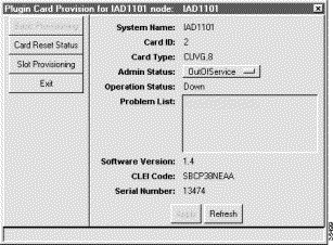
The plugin card provision window (see Figure 1-9) is used to set slot and card parameters, such as card type and administrative status (in service or out of service). See "About Placing Cards In Service", for provisioning information. After setting parameters, refresh the window to confirm the action.
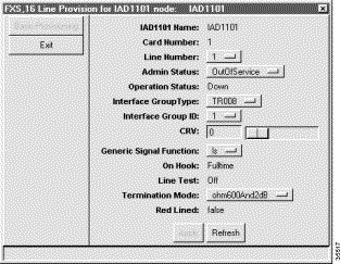
The line provision window (see Figure 1-10) is used to provision individual line parameters. Each type of line card uses a different line provision window; Figure 1-10 shows the line provision window for a FSX/16 card. (See "Provisioning Lines," for provisioning information.) After provisioning parameters, refresh the window to confirm the action.
During any procedure, you can confirm your work by clicking the Refresh button at the bottom of the window. The displayed values should conform to the newly entered parameters or most recent action.
The following sections describe the basic navigational techniques used to enter data and provision the NE.
The following terms are used in this guide to describe actions involving the mouse:
To select an individual icon, position the cursor over the icon. The icon turns orange when the cursor is positioned over the icon. Click, right-click, or double-click the highlighted icon.
Selecting one or more entries from an EMS list is referred to as highlighting the entries.
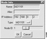
The node information window (see Figure 1-11) is used to describe several methods of entering data in EMS.
The following buttons appear in many EMS windows:
![]()
![]()
![]()
![]()
![]()
![]()
![]()
![]()
Posted: Mon Feb 5 12:51:50 PST 2001
All contents are Copyright © 1992--2001 Cisco Systems, Inc. All rights reserved.
Important Notices and Privacy Statement.