|
|

This chapter contains procedures for the initial provisioning of a network element (NE). You should complete these procedures in the following order:
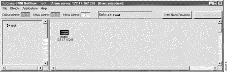
After launching EMS and logging in with a valid username and password, EMS presents the Cisco 6700 NetView. (See Figure 4-1.) NetView displays the network topology, including all nodes and subnets.

Before EMS can communicate with the NE, you must create a node in Cisco 6700 NetView. EMS uses nodes to represent each NE in the network.
 |
Note In the following procedure, the node name and node alias must not include spaces, quotation marks, or other nonalphanumeric characters. |

Step 2 Enter a node name (and optional node alias) for the NE. The node name identifies the node in Cisco 6700 NetView. The node alias provides additional description information (such as location or organization name).
Step 3 In the IP address text box, enter the primary IP address of the NE. If you are provisioning the NE for the first time, enter the default IP address: 192.168.0.2.
Step 4 In the Type field, select the proper NE type (6732, 6705, or IAD1101).
Step 5 EMS provides a default node ID number for the NE. Consult your EMS administrator for the correct node ID for use with this NE. Highlight the number and enter a new node ID, or use the slider to change the node ID.
Step 6 Click the OK button when finished. You will return to Cisco 6700 NetView. The newly-created node will appear as an icon, with the node name and IP address below the icon. (See Figure 4-3.)
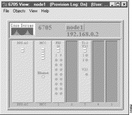
To verify connectivity between EMS and the NE, double-click the node icon in Cisco 6700 NetView (see Figure 4-3), or select NodeView from the popup menu. Depending on the chassis type, EMS launches the Cisco 6732 NodeView (Figure 4-4), the Cisco 6705 NodeView (Figure 4-5), or the Cisco IAD1101 NodeView (Figure 4-6).
|
Note To move a node icon, hold the Shift key and drag the icon with the mouse. |


If the node ID entered in EMS differs from the current node ID assigned to the NE, EMS reports a node ID conflict. (See Figure 4-7.)

To resolve a node ID conflict:
For example, if you create a node in Cisco 6700 NetView and assign a node ID of 3, but the NE is provisioned with a node ID of 1, EMS reports a node ID conflict when you double-click the node icon. Select Yes (see Figure 4-7) to change the NE node ID to 3. Select No to leave the NE with its node ID of 1.
If EMS is unable to connect with the NE, a warning message appears describing the problem. The following list identifies common issues that could prevent the EMS workstation from communicating with the NE:
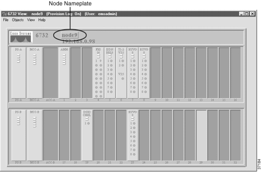
From Cisco 6700 NodeView, double-click the node nameplate. (See Figure 4-8.)
EMS launches the NE provision window. (See Figure 4-9.)
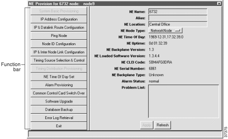
The left side of the window contains the function bar, a group of buttons used to navigate the NE provision window. Note that the System Basic Provisioning button is grayed out in the button bar. This indicates that the system basic provisioning window is open. To open a different provisioning window, click one of the buttons in the function bar.
|
Note The NE Loaded Software Version field refers to the MCC embedded software version, not to the EMS software version installed on your PC. |
The NE must be assigned an appropriate IP address before the NE can be introduced in the network. Your EMS administrator should provide IP information for the NE, including subnet masks.
 |
Caution Do not assign an IP address to the NE unless the IP address is specifically designated for this NE. Improper use and assignment of IP addresses can create severe problems, including network failure. |
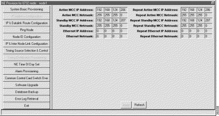
The Cisco 6732 NE is factory-configured with the following default IP addresses and subnet masks:
The Cisco 6705 NE is factory-configured with the following default IP address and subnet mask:
The Cisco IAD1101 NE is factory-configured with the following default IP address and subnet mask:
Step 2 Enter the IP addresses and netmasks provided by your EMS administrator. Be sure to repeat all entries in the Repeat fields on the right.
Step 3 The Ethernet IP Address and Ethernet Netmask allow you to specify a separate route for the Ethernet port on the NE. If the Ethernet IP address is left unassigned (0.0.0.0), the Ethernet port will use the IP address of the active MCC.
Step 4 Click the Apply button to confirm the IP address provisioning. EMS displays a warning message, indicating that you will disconnect from the NE. Click Yes to confirm the changes.
|
Note After entering an address or netmask, you must enter the same address/netmask in the Repeat fields (on the right side of the window). For example, if you enter 1.2.3.4 as the Active MCC IP Address, you must also enter 1.2.3.4 in the Repeat Active MCC IP Address field. EMS does not allow you to apply your changes unless all entries are repeated properly. |
|
Note After assigning a new IP address, the EMS workstation will lose contact with the NE. To further provision the NE, configure the IP address of the EMS workstation on the same IP network as the NE. See "Configuring TCP/IP on the EMS Workstation" for more information. |
To allow remote management and provisioning, you must create a default route from the remote node to the local node. For example, you would need a default gateway pointing to the IP address of the local node if you have multiple Cisco 6700 series products on different subnets and use a router to communicate between them.
Step 2 Double-click the node nameplate. EMS launches the NE provision window.
Step 3 From the function bar on the left, click on the IP & Datalink Route Configuration button. This brings up the data-link route configuration window. (See Figure 4-11.)
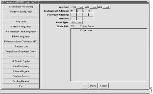
Step 4 Set the following parameters in the data-link route configuration window:
Step 5 Click Add when you are finished.
Step 6 Click the Exit button (on the function bar) to return to the NodeView.
Step 7 Select File > Exit to return to Cisco 6700 NetView.
|
Note As an alternative to entering the gateway address in Step 4, open the command prompt window and enter (for example): C:>route add 172.17.30.26 192.168.124. 250 (route add<remote IP> <local IP>) |
Any changes made to the NE IP address must also be made to the node.
|
Note If you begin the following procedure from Cisco 6700 NetView, skip to Step 3. |
Step 2 Select File > Exit from the menu bar. EMS returns to Cisco 6700 NetView.
Step 3 Right-click the node icon to bring up the node popup menu.
Step 4 Select Display Node Attributes to view the node information window. (See Figure 4-12.)
Step 5 In the IP Address field, enter the IP address that has been assigned to the NE in the "Assigning Network IP Addresses for the NE" procedure. (See page 4-9.) For the Cisco 6732, this is the Active MCC IP Address; for the Cisco 6705, this is the MCC IP Address.
Step 6 Click OK. EMS returns to Cisco 6700 NetView. The node icon displays the newly assigned IP address.
The following procedures are completed in the NE provision window, and must be completed for each NE in the network. To bring up the NE provisioning window, double-click the node nameplate in Cisco 6700 NodeView. (See Figure 4-9.)
Each NE can send alarms to one or more EMS alarm servers. EMS workstations using Windows NT or UNIX use the EMS alarm server application to gather alarms from the Network. Use of the alarm server is detailed in "Cisco 6700 Series Element Management System Alarm Server."
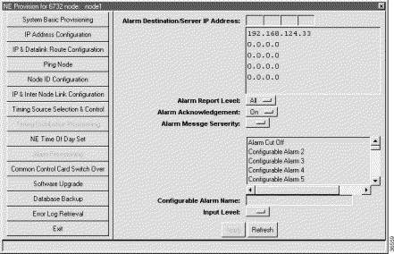
Step 2 Click an IP address in the list below the Alarm Destination/Server IP Address field.
Step 3 Enter the IP address of an alarm destination (EMS alarm server).
Step 4 To customize alarm reporting for this alarm server, set the following fields:
Step 5 To customize any of the 16 alarm inputs, click an alarm name in the list below Alarm Message Severity.
Step 6 In the Alarm Message Severity field, select the severity level of the alarm: Critical, Major, or Minor.
Step 7 To change the name of the alarm, type a new name in the Configurable Alarm Name field.
Step 8 Return to Step 5 to customize additional alarm inputs.
Step 9 Click Apply to provision the alarm server.
Step 10 To configure additional alarm servers, return to Step 2 and click a different IP address from the list.
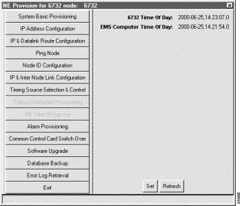
Setting the node clock synchronizes the NE clock with the EMS clock.
Step 2 Click the Set button to synchronize the NE clock with the EMS workstation clock.
The Refresh button updates the time displayed on the screen. (See Figure 4-14, which shows the Set NE Time of Day window, before synchronization.)
|
Note All Cisco 6700 Series line interface modules are synchronized to Greenwich Mean Time (GMT), rather than the "Time of Day" setting on the EMS workstation. One-day performance monitoring (PM) tests use GMT, not the EMS time of day, to determine the start and end times of the 24-hour monitoring window. |
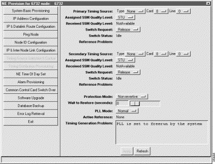
Step 2 To provision a timing source for the NE, set the following fields:
|
Note You can select the same card and line for both the primary and secondary timing sources. However, this configuration offers no redundancy and should only be used temporarily during reconfigurations. |
Step 3 Click Apply to provision a timing source or sources for the NE.
If the Primary Timing Source is disqualified due to an "out-of-frequency range" error, the primary input will not automatically requalify after the error ends.You must manually requalify it.
Step 2 Select None from the drop-down menu.
Step 3 Click Apply.
Step 4 In the primary timing source Type field, reselect the primary timing source.
Step 5 Click Apply.
![]()
![]()
![]()
![]()
![]()
![]()
![]()
![]()
Posted: Mon Feb 5 12:54:05 PST 2001
All contents are Copyright © 1992--2001 Cisco Systems, Inc. All rights reserved.
Important Notices and Privacy Statement.