|
|

This chapter guides you through installing the Cisco ONS 15104 and includes the following sections:
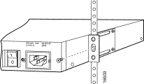
This section explains how to rack-mount the Cisco ONS 15104 chassis on a 19-inch Telco or equipment rack. The Cisco ONS 15104 comes with two brackets. Figure 4-1 shows two of the brackets used with a 19-inch rack.

Step 2 Align the brackets to the right and left sides of the chassis. Use the screws that are supplied in the cable accessory kit to attach the brackets to the chassis. (See Figure 4-2.)

Step 3 Install the Cisco ONS 15104 in a rack with the front panel forward.
Step 4 Align the mounting brackets on the Cisco ONS 15104 chassis to holes in the rack.
Step 5 Use the screws that are supplied in the cable accessory kit to attach each side of the
Cisco ONS 15104 chassis to the rack. (See Figure 4-3.)
 | Caution Do not place anything on top of the Cisco ONS 15104 that weighs more than 10 pounds (4.5 kilograms [kg]). More weight on top could damage the Cisco ONS 15104. |
The cable accessory kit contains the cables you need to connect the Cisco ONS 15104 to another device. You will need the following cables to connect the Cisco ONS 15104 to other devices on the network:
To order additional cables, see the "Service and Support" section in the "About This Guide" preface. For cable pinouts, refer to the "Cable Specifications."
For SONET/SDH connections to the Cisco ONS 15104 do the following:
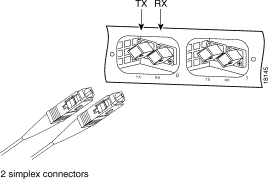
Figure 4-4 shows a simplex SC cable connector. Be sure to observe the receive (Rx) and transmit (Tx) cable relationship, which means that an Rx port on one line card must be connected to a Tx port on the next line card.
 | Warning
Invisible laser radiation can be emitted from the aperture of the port when no cable is connected. Avoid exposure to laser radiation and do not stare into open apertures. |
 | Warning
Class 1 laser product (single-mode). |
You can attach the cable-management bracket to the left front side of the Cisco ONS 15104 in the area over the Ethernet and console ports. (See Figure 4-5.)

Follow these steps to insert the cable-management bracket:
Step 2 Insert the flat end of the bracket into the slit, with the rounded end pointing up. Push the flat end into the bend in the bracket.
Step 3 Rotate the bracket downward, so that it is parallel to the Cisco ONS 15104.
Step 4 Guide the interface cables toward the left side of the Cisco ONS 15104, away from the SC connectors, and through the rounded end of the cable-management bracket.
This section describes two options for connecting the Cisco ONS 15104 to your network. Use one of these methods in the following section to configure the Cisco ONS 15104 for local or network connections:
or
 | Warning This equipment must be grounded when there is an AC or a DC power supply. Ensure that the Cisco ONS 15104 is connected to a system (earth) grounding receptacle during normal use. For details, see the "Supplemental Unit Bonding and Grounding Guidelines for AC input" section or "Supplemental Unit Bonding and Grounding Guidelines for DC Input" section. |
 | Warning
The console ports contain safety extra-low voltage (SELV) circuits. |
The following sections describe hardware configuration options for connecting the
Cisco ONS 15104 console port to other devices.
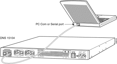
Use a console port cable (RJ-45 rollover cable) to connect a PC com or serial port directly to the Cisco ONS 15104 console port. After connecting a PC to the console port, you can use suitable terminal emulation software to communicate with the Cisco ONS 15104. (See Figure 4-6.)
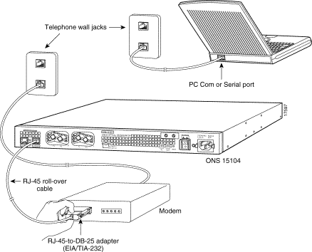
You can use a PC with an internal or external modem to configure the Cisco ONS 15104 that is located at a remote site. To connect with a modem, do the following:
Step 2 Connect the opposite end of the console port cable with an RJ-45 to DB-25 adapter (EIA/TIA-232) to a modem.
Step 3 Dial the telephone number of the modem that is connected to the Cisco ONS 15104. You can configure the Cisco ONS 15104 remotely through the PC modem. (See Figure 4-7.)
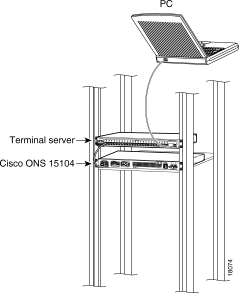
You can link Cisco ONS 15104's console port to a LAN network through a terminal server. The Cisco terminal server has a maximum of 16 serial port lines. Each serial port line is numbered
1 through 16. The terminal server serial port line number becomes the terminal server address.
To configure the Cisco ONS 15104 to a terminal server do the following:
Step 2 Connect the terminal server serial port to the PC terminal serial port.
Step 3 Power on the Cisco ONS 15104.
Step 4 To boot the Cisco ONS 15104, do the following:
Router# telnet line 5
Router#
or
Router# <terminal server name> 2005
Router# <terminal server IP address> 2005
Router#
Figure 4-8 shows the Cisco ONS 15104 connected to a terminal server and a PC terminal serial port.
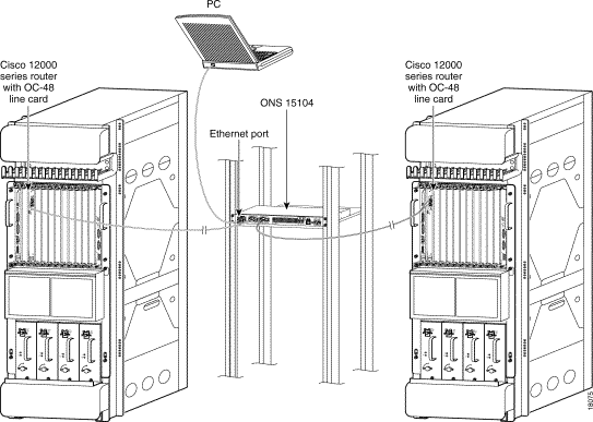
This section describes a Cisco ONS 15104 and an OC-48 line card installed in each Cisco 12000 series GSR at two remote sites.
Two single simplex SC connector cables are usually tied together as pairs, so they will appear as one cable with Rx and Tx connectors at each end. Be sure to disconnect and reconnect the cables using the receive (Rx) and transmit (Tx) cabling relationship.
To connect the OC-48 line cards that are installed in two Cisco 12000 series GSRs do the following:
Step 2 Connect the opposite end of the simplex SC cable to the left Rx SC connector on an OC-48 line card. Connect the opposite end of the simplex SC cable to the left Tx SC connector on an OC-48 line card.
Step 3 Connect a simplex SC cable connector to the Cisco ONS 15104's right Tx OC-48 regeneration port on side 1. Connect a simplex SC cable connector to the
Cisco ONS 15104's right Rx OC-48 regeneration port on side 1.
Step 4 Connect the opposite end of the simplex SC cable to the right Rx SC connector on an OC-48 line card. Connect the opposite end of the simplex SC cable to the right Tx SC connector on an OC-48 line card.
Step 5 Repeat steps 1 and 4 for all OC-48 line cards that will be connected to a Cisco ONS 15104 on the network.
Step 6 Use a PC or VTY terminal to configure the Cisco ONS 15104 and communicate with other network devices.
Figure 4-9 shows the Cisco ONS 15104 configured to OC-48 line cards installed in two Cisco 12000 series GSRs.
This completes configuration of two OC-48 line cards to Cisco ONS 15104.
When you finish connecting the Cisco ONS 15104 to the network through a port, you can boot up the Cisco ONS 15104 and configure the interfaces. For software configuration information, proceed to "Configuring the Cisco ONS 15104,".
![]()
![]()
![]()
![]()
![]()
![]()
![]()
![]()
Posted: Fri Jan 5 07:50:34 PST 2001
All contents are Copyright © 1992--2001 Cisco Systems, Inc. All rights reserved.
Important Notices and Privacy Statement.