|
|

Table Of Contents
Console Port Signals and Pinouts
Cable Specifications
This appendix describes the ports and connectors that are used to configure the Cisco ONS 15104 to other network components. It covers the following information:
•
Console Port Signals and Pinouts
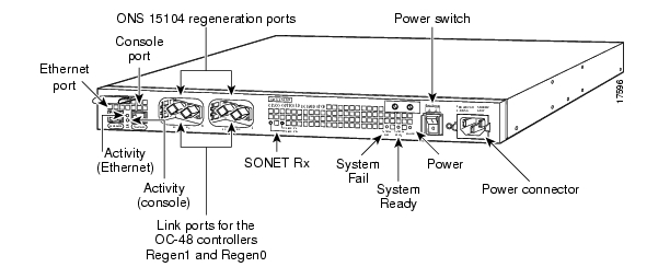
For configuration examples using cables with Cisco ONS 15104 ports and connectors, see "Connecting to Your Network" in Chapter 4, "Installing the Cisco ONS 15104.". See to review the locations of the Ethernet and console ports and fiber-optic connectors.
Figure B-1 Cisco ONS 15104 Front Panel
Cable Accessory Kit
The Cisco ONS 15104 comes with a cable accessory kit that contains the cables and adapters you need to connect a terminal, a PC running communication software, or a modem to your
Cisco ONS 15104. The cable accessory kit includes the following items:•
•
•
•
•
•
•
•
Note
Console Port Signals and Pinouts
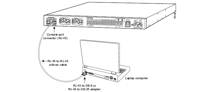
Use the RJ-45 to RJ-45 rollover cable and RJ-45 to DB-9 female DTE adapter (labeled Terminal) to connect the console port to a PC running terminal emulation software. lists the pinouts for the console port cable and adapter. (See .)
Figure B-2 Console Port and Console Port Connector (RJ-45)
Identifying a Rollover Cable
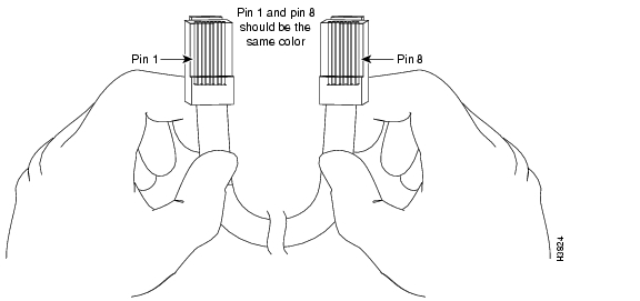
You can identify a rollover cable by comparing the two modular ends of the cable. Hold the cables side-by-side, with the tab at the back, the wire connected to the pin on the outside of the left plug should be the same color as the wire connected to the pin on the outside of the right plug. (See .) If your cable came from Cisco Systems, pin 1 will be white on one connector, but pin 8 will be white on the other (a rollover cable reverses pins 1 and 8, 2 and 7, 3 and 6, plus 4 and 5).
Figure B-3 Identifying a Rollover Cable
Table B-1 shows the pin-outs for the DB-9 adapter. Use the RJ-45-to-RJ-45 rollover cable and RJ-45-to-DB-25 female DTE adapter (labeled Terminal) to connect the console port to a terminal.
Table B-1 Console Port Signaling and Cabling Using a DB-9 Adapter
RTS
11
8
8
CTS
DTR
2
7
6
DSR
TxD
3
6
2
RxD
GND
4
5
5
GND
GND
5
4
5
GND
RxD
6
3
3
TxD
DSR
7
3
4
DTR
CTS
81
1
7
RTS
1 Pin 1 is connected internally to pin 8.
lists the pinouts for the asynchronous serial console port, the RJ-45 to RJ-45 rollover cable, and the RJ-45 to DB-25 female DTE adapter (labeled Terminal).
Table B-2 Console Port Signaling and Cabling Using a DB-25 Adapter
RTS
12
8
5
CTS
DTR
2
7
6
DSR
TxD
3
6
3
RxD
GND
4
5
7
GND
GND
5
4
7
GND
RxD
6
3
2
TxD
DSR
7
3
20
DTR
CTS
81
1
4
RTS
1 You can use the same cabling to connect a console to the auxiliary port.
2 Pin 1 is connected internally to pin 8.
Ethernet Port Signals
The Ethernet port is used to download Cisco IOS software images to the Cisco ONS 15104. However, the Ethernet port must be configured through a PC terminal before you can download files. You can use a straight Ethernet cable to connect and configure the Cisco ONS 15104 to other components through the Ethernet port.
Fiber Connectors
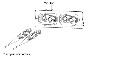
The Cisco ONS 15104 has two pair of fiber connectors for bidirectional transmission. The left fiber connector interfaces with an OC-48 regeneration port that transmits data. The right fiber connector interfaces with an OC-48 regeneration port that receives data. The SC connector supports single-mode, fiber-optic transmissions. The SC connector is the default connector for the
Cisco ONS 15104 as specified by the Telecommunications Industry Association (TIA) as the Fiber-Optic Cable Intermatability Standard (FOCIS-3). (See Figure B-4.)Figure B-4 OC-48 Regeneration Ports with Fiber Connectors
![]()
![]()
![]()
![]()
![]()
![]()
![]()
![]()
Posted: Tue Dec 7 08:02:54 PST 2004
All contents are Copyright © 1992--2004 Cisco Systems, Inc. All rights reserved.
Important Notices and Privacy Statement.