|
|

This chapter provides an overview of the Cisco ONS 15104 and includes the following sections:
The Cisco ONS 15104 is a bidirectional OC-48/STM-16 regenerator that transmits optical signals over the longest distance possible. It supports single-mode long reach optical-fiber transmission when connected to an OC-48 line card that is installed in a Cisco 12000 series Gigabit Switch Router (GSR).
The Synchronous Optical Network (SONET) specification for fiber-optic transmission defines the standard for single-mode fiber. The Cisco ONS 15104 provides an end-to-end Internet Protocol (IP) transport for long distances by forwarding SONET/SDH traffic at OC-48 line rates.
The Cisco ONS 15104 uses only single-mode fiber because signals can travel farthest through single-mode long reach fiber. The maximum distance for single-mode installations of the
Cisco ONS 15104 is determined by the amount of light loss in the fiber path, as well as by the physical limitation of transmitting optical fiber to optical light over exceptionally long distances. High-quality single-mode fiber with minimal high-quality splices can carry a Cisco ONS 15104 signal up to 50 miles (80 kilometers (km)). Table 1-1 describes the power budget and signal requirements for each Cisco ONS 15104 used in an OC-48 SONET installation.
| Transceiver | Power Budget | Transmit Power | Receive Power | Typical Maximum Distance |
|---|---|---|---|---|
Single-mode | 26 dB | -2.0 to 3.0 dBm1 at 1500 to 1580 nm2 | -28 to -9 dBm | 80 km |
| 1dBm = relative to 1 milliwatt 2nm = nanometer |
When you connect the OC-48 line cards that are installed in two Cisco 12000 series GSRs, without a Cisco ONS 15104, you are limited to a maximum distance of 80 km. (See Figure 1-1).
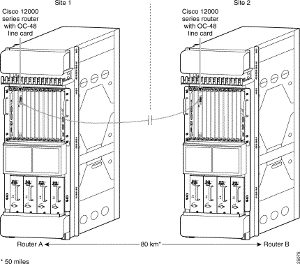
Figure 1-2 shows an OC-48 line card installed in each Cisco 12000 series GSR, with a
Cisco ONS 15104 configured between them. Each OC-48 regeneration port connects to an OC-48 line card installed in a Cisco 12000 series GSR. Each OC-48 regeneration port is labeled
side 0 Tx and Rx, and side 1 Tx and Rx, which corresponds to SONET/Section Data Communication Channel (SONET/SDCC) interfaces, SDCC0 and SDCC1.
The distance from router A to the Cisco ONS 15104 is 80 km (50 miles), and the distance from the Cisco ONS 15104 to router B is 80 km (50 miles), for a maximum distance of up to
160 km (100 miles).
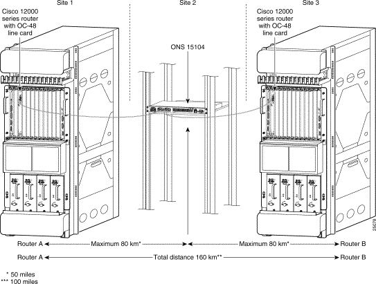
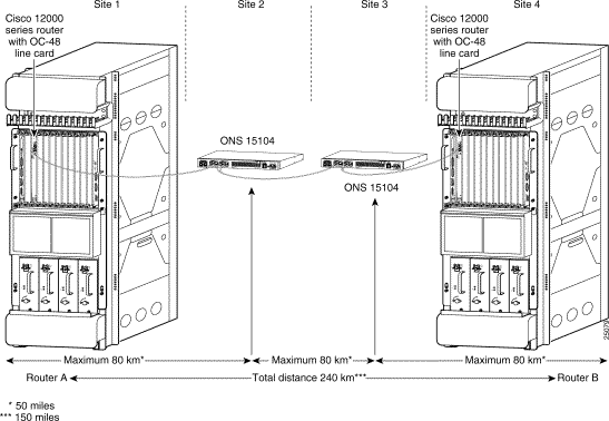
Figure 1-3 shows an OC-48 line cards installed in each Cisco 12000 series GSR with two
Cisco ONS 15104s configured between them. The distance from router A to the first
Cisco ONS 15104 is 80 km (50 miles), the distance from the first Cisco ONS 15104 to the second
Cisco ONS 15104 is 80 km (50 miles), the distance from the second Cisco ONS 15104 to router B is 80 km (50 miles), for a maximum distance of up to 240 km (150 miles).
By using the Cisco ONS 15104 in an OC-48 SONET installation, you can significantly extend the separation between any two Cisco 12000 series GSRs, depending on the quality of the fiber-optic cabling. The location and number of splices in the fiber-optic cabling may reduce the maximum allowable distance.
This section provides an overview of the external hardware of the Cisco ONS 15104. Figure 1-4 shows the location of the Cisco ONS 15104's ports, interfaces, LEDs, power switch, and AC power connector on the AC-powered version.
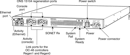
Figure 1-5 shows the location of the Cisco ONS 15104's ports, interfaces, LEDs, and DC terminal block on the DC-powered version.

A configured Cisco ONS 15104 has one AC power supply or one DC power supply. The
Cisco ONS 15104 is delivered with the type of power supply that you ordered, installed by the manufacturer. Site requirements for the AC-input and DC-input power supplies differ, depending on the type of required source voltage. The power supply specifications in "Power Guidelines" will help you to plan where to install the Cisco ONS 15104. Be sure to plan for close proximity of site components for easy cabling configuration.
The Cisco ONS 15104 supports four types of ports and interfaces. (See Table 1-2.)
| Name | Type | Purpose | Inband/Out-of-Band |
|---|---|---|---|
Console | Physical port | Local (or remote) Management | Out-of-band |
Ethernet | Physical port | Local (or remote) Management | Out-of-band |
OC-48/STM-16 Regeneration | Physical ports | Traffic | N/A |
SDCC | Logical port | Remote Management | Inband |
The OC-48/STM-16 traffic ports begin operation as soon as the Cisco ONS 15104 is powered up. The other ports must be correctly configured before use. (For details, see "Configuring the Cisco ONS 15104.")
The Cisco ONS 15104 console port provides local access through a console terminal or remote access for a console terminal through a modem. The console port is an asynchronous serial EIA/TIA-232 interface that is compatible with an RJ-45 jack on the front panel. The console port supports flow control.
The Cisco ONS 15104 has a 10BaseT Ethernet port that operates in half-duplex mode. It supports up to 10-megabits-per-second (Mbps) transfer rates. The Ethernet port uses an RJ-45 jack on the front panel. This port is used for local or remote management of the Cisco ONS 15104 via an out-of-band management.
There are two pairs of these ports: one for the device to the left (such as a Cisco 12000 series GSR), and one for the device to the right. SONET/SDH traffic flows through these ports which provide access to the regeneration function at the heart of the Cisco ONS 15104. Each pair comprises a single transmit (Tx) and a single receive (Rx) connector. The ports use SC connectors on the front panel.

The SDCC interfaces (SDCC0, SDCC1) are logical interfaces within the Cisco ONS 15104 that provide access to the Data Communications Channel (DCC) in the SONET/SDH Section/Regenerator Section overhead of the OC-48/STM-16 traffic. The DCC uses bytes D1, D2, and D3 to form an in-band 192 kilobits-per-second (kbps) channel for Operations, Administration and Maintenance (OAM) messages between pieces of section terminating equipment (such as, regenerators and routers) The Cisco ONS 15104 expects its OAM information to be carried within HDLC-encapsulated IP packets.
The DCC acts as a pseudo local area network (LAN) connecting all the Cisco ONS 15104s in a single chain between a pair of routers. All the SDCC interfaces must either be in the same subnet, or each link between a pair of Cisco ONS 15104s must be in a different subnet. There must be IP routing configured between them.
As described previously, SONET/SDH traffic flows through the OC-48/STM-16 regeneration ports to access the retiming, resynchronizing and reamplification regeneration function. This function is represented within the Cisco ONS 15104 as two unidirectional regeneration controllers, regen 0 and regen 1. Also, they give the SDCC logical interfaces access to the Data Communications Channel in the SONET/SDH overhead. In the SONET world, the regen controllers are known as Section Terminating Equipment (STEs).
Figure 1-7 shows the relationship between the regen controllers and the OC-48/STM-16 ports.
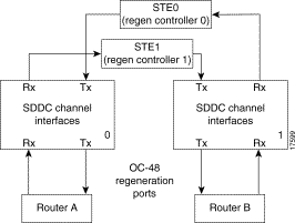
The two regen controllers default to SONET framing, so they must be configured for SDH framing when used in an SDH network.
Table 1-3 lists the Cisco ONS 15104 system specifications.
| Description | Specification |
|---|---|
Dimensions (H x W x D) | 1.72 x 17.3 x 11.8 inches, one rack unit (4.37 x 43.94 x 29.97 cm) |
10.3 lbs. | |
Input voltage, AC power supply | 100 to 240 VAC1 |
-48/-60 VDC3 | |
40-MHz Motorola MPC860 | |
Ethernet 10BaseT (RJ-45) | |
OC-48 SONET/STM16 SDH interface | |
Console port | Asynchronous serial port |
Operating environment | 32 to 104ºF (0 to 40ºC) |
-40 to 185ºF (-40 to 85ºC) | |
5 to 95%, noncondensing | |
51 dbA4 at 3 feet (0.914m) |
| 1VAC = volts alternating current 2BTU = British thermal unit 3VDC = volts direct current. 4dbA = decibels Acoustic |
Cisco ONS 15104 software includes the following components:
Cisco IOS software is used to do the following:
![]()
![]()
![]()
![]()
![]()
![]()
![]()
![]()
Posted: Fri Jan 5 07:51:36 PST 2001
All contents are Copyright © 1992--2001 Cisco Systems, Inc. All rights reserved.
Important Notices and Privacy Statement.