|
|

Table Of Contents
Implementing and Configuring the Solution
Configuring a Point-to-Point and Multihop Ethernet Topology
Implementing the Cisco ONS 15216 FlexLayer
Implementing the Cisco ONS 15216 OSC-1510
Implementing and Configuring Cisco Video Gateways
Implementing and Configuring the Cisco uMG9820 QAM Gateway
Implementing and Configuring the Cisco uMG9850 QAM Module
Implementing and Configuring the Solution
This chapter presents the following major tasks:
•
Configuring a Point-to-Point and Multihop Ethernet Topology
•
Configuring a Point-to-Point and Multihop Ethernet Topology
This section addresses the following:
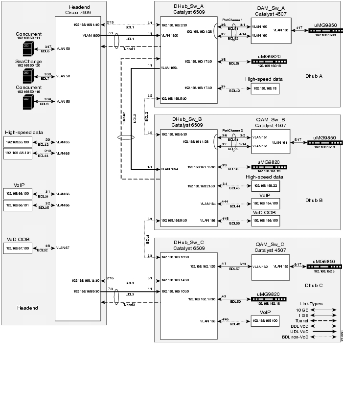
Figure 3-1 illustrates the point-to-point and multihop Ethernet topology discussed in this section. Table 3-1 lists the loopback and VLAN IP addresses for the headend, Dhub, and QAM switches.
Figure 3-1 Example Point-to-Point and Multihop Topology
Configuring the Headend
This section addresses the configuration required on the switch labeled Headend in Figure 3-1, to route multiple services from the headend switch to the Dhubs. The headend consists of VoD servers, VoIP equipment, high-speed data equipment, VoD OOB (out-of-band) equipment, and a Cisco 7609. A Cisco Catalyst 6509 can also be used, as they use the same supervisor engine.
Note
— Cisco Catalyst 6500 Series Switches:
http://www.cisco.com/univercd/cc/td/doc/product/lan/cat6000/index.htm
— Cisco 7600 Series Router:
http://www.cisco.com/univercd/cc/td/doc/product/core/cis7600/index.htmThis section addresses the following:
•
•
•
•
These are configured on the Cisco 7609 labeled Headend in Figure 3-1. For a complete configuration example, see "Sample Configuration for a Headend Switch."
Confirming Hardware
Before proceeding, it is beneficial to use the show modules command to confirm the hardware components and their versions for each switch.
The following is executed on Headend.
Step 1
Headend# show modulesMod Ports Card Type Model--- ----- -------------------------------------- ------------------1 16 Pure SFM-mode 16 port 1000mb GBIC WS-X6816-GBIC2 16 Pure SFM-mode 16 port 1000mb GBIC WS-X6816-GBIC3 48 CEF720 48 port 10/100/1000mb Ethernet WS-X6748-GE-TX5 2 Supervisor Engine 720 (Active) WS-SUP720-BASE7 4 CEF720 4 port 10-Gigabit Ethernet WS-X6704-10GEMod Sub-Module Model Hw--- --------------------------- ------------------ -------1 Distributed Forwarding Card WS-F6K-DFC3A 2.02 Distributed Forwarding Card WS-F6K-DFC3A 2.03 Centralized Forwarding Card WS-F6700-CFC 1.25 Policy Feature Card 3 WS-F6K-PFC3BXL 1.25 MSFC3 Daughterboard WS-SUP720 2.17 Distributed Forwarding Card WS-F6700-DFC3A 2.1Establishing Quality of Service (QoS)
This section addresses the configuration of QoS (see Routing and QoS) in the point-to-point and multihop topology depicted in Figure 3-1, to provide different degrees of quality of service for the different types of services supported by the solution architecture. For example, it is important to ensure the expeditious delivery of video and VoIP traffic, while providing only best-effort delivery for high-speed data.
By default, the Cisco 7600 series router and Cisco Catalyst 6500 series switch do not trust the incoming QoS markings, and therefore rewrite these bits with zeros. In this solution, packets at the network ingress ports are identified, classified, and marked according to type of traffic. The packets are marked with one of 64 possible Differentiated Services Code Point (DSCP) values at the ingress ports. (See DSCP Features and Values Used in Release 2.0.) These in turn are internally mapped to one of eight possible Class of Service (CoS) values, because CoS is used to determine the appropriate transmit queue for each packet.
The following is configured on Headend.
Note
http://www.cisco.com/warp/public/cc/pd/iosw/iore/tech/osfea_wp.htm
Step 1
mls qosStep 2
VoD server traffic has two levels of priority, high and low. The User Datagram Protocol (UDP) port range for the GE QAM gateways is divided in half, with the upper half considered high priority and the lower half considered low priority. In customer networks, assigning priorities depends on the service groups used by the customer.
Note
ip access-list extended acl_VoD_OOBremark Identify VoD OOB traffic.permit ip 192.168.67.0 0.0.0.255 anyip access-list extended acl_VoIPremark Identify VoIP traffic.permit ip 192.168.66.0 0.0.0.255 anyip access-list extended acl_high_speed_dataremark Identify high speed data.permit ip 192.168.65.0 0.0.0.255 anyip access-list extended acl_video_highremark Identify high priority VoD server traffic.permit udp 192.168.48.0 0.0.7.255 192.168.160.0 0.0.3.255 range 3329 6399ip access-list extended acl_video_lowremark Identify low priority VoD server traffic.permit udp 192.168.48.0 0.0.7.255 192.168.160.0 0.0.3.255 range 257 3327Step 3
class-map match-all class_VoD_OOBmatch access-group name acl_VoD_OOBclass-map match-all class_VoIPmatch access-group name acl_VoIPclass-map match-all class_high_speed_datamatch access-group name acl_high_speed_dataclass-map match-all class_video_highmatch access-group name acl_video_highclass-map match-all class_video_lowmatch access-group name acl_video_lowStep 4
policy-map setDSCPdescription Mark DSCP values for the different types of trafficclass class_VoD_OOBset dscp cs3class class_VoIPset dscp efclass class_high_speed_dataset dscp defaultclass class_video_highset dscp cs4class class_video_lowset dscp af41Step 5
At the beginning of this section, we mentioned that there are 64 possible DSCP values and only 8 CoS values. This means that there could be more than one DSCP value for one CoS value. The following command shows the default DSCP-to-CoS mapping. The highlighted values are for the non-video traffic. This table shows that high-speed data (DSCP = 0) is mapped to CoS = 0, VoD OOB (DSCP = 24) is mapped to CoS = 3, and VoIP (DSCP = 46) is mapped to CoS = 5. (Note that d1 corresponds to the x-axis value of the table, and d2 to the y-axis value.)
Headend# show mls qos maps dscp-cosDscp-cos map: (dscp= d1d2)d1 : d2 0 1 2 3 4 5 6 7 8 9-------------------------------------0 : 00 00 00 00 00 00 00 00 01 011 : 01 01 01 01 01 01 02 02 02 022 : 02 02 02 02 03 03 03 03 03 033 : 03 03 04 04 04 04 04 04 04 044 : 05 05 05 05 05 05 05 05 06 065 : 06 06 06 06 06 06 07 07 07 076 : 07 07 07 07In this configuration, the non-video traffic is carried on the GE interfaces. Use the following command on these interfaces to see if these CoS values are assigned to the correct transmit queues.
Note
show queueing interface gigabitEthernet 2/15Interface GigabitEthernet2/15 queueing strategy: Weighted Round-RobinQueueing Mode In Tx direction: mode-cosTransmit queues [type = 1p2q2t]:Queue Id Scheduling Num of thresholds-----------------------------------------1 WRR low 22 WRR high 23 Priority 1Packets dropped on Transmit:BPDU packets: 0queue thresh dropped [cos-map]---------------------------------------------------1 1 0 [0 1 ]1 2 0 [2 3 ]2 1 0 [4 6 ]2 2 0* [7 ]3 1 0* [5 ]* - shared transmit counterFrom the output, we can see that high-speed data and VoD OOB traffic are put into Tx Queue 1, VoD OOB traffic is put into Tx Queue 2, and VoIP traffic is put into Tx Queue 3 (which is the priority queue). The default mappings from DSCP to CoS and from CoS to transmit queue are correct for the non-video traffic types.
Step 6
Below is the same default DSCP-to-CoS mapping, but with the values for high- and low-priority video traffic highlighted. This table shows that both low-priority video (DSCP = 34) and high-priority video (DSCP = 32) are mapped to CoS = 4. The solution specifies that high-priority video traffic be put in the priority transmit queue, and low-priority video traffic be put in a nonpriority queue.
Headend# show mls qos maps dscp-cosDscp-cos map: (dscp= d1d2)d1 : d2 0 1 2 3 4 5 6 7 8 9-------------------------------------0 : 00 00 00 00 00 00 00 00 01 011 : 01 01 01 01 01 01 02 02 02 022 : 02 02 02 02 03 03 03 03 03 033 : 03 03 04 04 04 04 04 04 04 044 : 05 05 05 05 05 05 05 05 06 065 : 06 06 06 06 06 06 07 07 07 076 : 07 07 07 07Next we must look at a 10-GE transport interface to see how the CoS values are assigned to transmit queues.
Note
Headend# show queueing interface tenGigabitEthernet 7/1Interface TenGigabitEthernet7/1 queueing strategy: Weighted Round-RobinQueueing Mode In Tx direction: mode-cosTransmit queues [type = 1p7q8t]:Queue Id Scheduling Num of thresholds-----------------------------------------01 WRR 0802 WRR 0803 WRR 0804 WRR 0805 WRR 0806 WRR 0807 WRR 0808 Priority 01Packets dropped on Transmit:queue dropped [cos-map]---------------------------------------------1 0 [0 1 ]2 0 [2 3 4 ]3 0 [6 7 ]4 0 []5 0 []6 0 []7 0 []8 0 [5 ]We want to keep low-priority video traffic in Transmit Queue 2, but move high-priority video traffic to Transmit Queue 8. This requires us to modify the default DSCP-to-CoS mapping for a DSCP value of 32 from a CoS of 4 to a CoS of 5.
Step 7
mls qos map dscp-cos 32 to 5Step 8
Looking at the DSCP-to-CoS mapping again, we can see that a DSCP value of 32 is mapped to a CoS of 5.
Headend# show mls qos maps dscp-cosDscp-cos map: (dscp= d1d2)d1 : d2 0 1 2 3 4 5 6 7 8 9-------------------------------------0 : 00 00 00 00 00 00 00 00 01 011 : 01 01 01 01 01 01 02 02 02 022 : 02 02 02 02 03 03 03 03 03 033 : 03 03 05 04 04 04 04 04 04 044 : 05 05 05 05 05 05 05 05 06 065 : 06 06 06 06 06 06 07 07 07 076 : 07 07 07 07Step 9
service-policy input setDSCPStep 10
mls qos trust dscpEnabling OSPF and VRF-lite for Video-over-IP Traffic
The solution specification uses VRF-lite (VPN routing and forwarding) to allow video and non-video traffic to be routed independently. (For more information, see Using VRF-lite and Differentiated Services in a Converged Multiservice Architecture.) All interfaces that carry video traffic are put into a VRF routing table, and all interfaces that carry non-video traffic are put in the global routing table.
The following is configured on Headend.
Step 1
The following command creates a VRF routing table and a Cisco Express Forwarding (CEF) table, both named "Video." The rd command defines a route distinguisher, which can be in the form of ASN:nn, IP-address:nn, or arbitrary-number:nn.
ip vrf Videodescription Video traffic destined for DHubsrd 1000:1Step 2
For Headend, this includes VLANs 50 and 1690, and TenGigabitEthernet7/3. An interface cannot be assigned to both the "Video" VRF routing table and the global routing table at the same time.
Caution
ip vrf forwarding VideoStep 3
The router ospf 100 vrf Video command associates the "Video" VRF routing table with OSPF routing process 100. Because the solution does not use Border Gateway Protocol (BGP), the capability vrf-lite command is used to suppress specific checks on the switch when the OSPF process is associated with the VRF routing table. The network statements should include all interfaces that carry video traffic. This includes all VoD server ingress ports and the transport interfaces to the Dhubs.
router ospf 100 vrf Videolog-adjacency-changescapability vrf-litenetwork 192.168.50.0 0.0.0.255 area 0network 192.168.169.0 0.0.0.3 area 0network 192.168.169.8 0.0.0.3 area 0network 192.168.169.32 0.0.0.3 area 0network 192.168.169.36 0.0.0.3 area 0
Note
Enabling OSPF for Non-video Traffic
The solution specification uses the global routing table for non-video traffic. All interfaces that carry non-video traffic are put into the global routing table. This includes VoIP ingress ports, VoD OOB ingress ports, high speed data ingress ports, the transport interfaces that carry this traffic and the loopback interfaces. The loopback interfaces serve as the endpoints for the GRE tunnels that are the bidirectional return paths for the unidirectional links between the headend and Dhubs.
The following is configured on Headend.
Step 1
router ospf 101log-adjacency-changesnetwork 1.14.0.0 0.0.255.255 area 0network 10.10.10.10 0.0.0.0 area 0network 14.14.14.14 0.0.0.0 area 0network 192.168.65.0 0.0.0.255 area 0network 192.168.66.0 0.0.0.255 area 0network 192.168.67.0 0.0.0.255 area 0network 192.168.168.0 0.0.0.3 area 0network 192.168.168.12 0.0.0.3 area 0
Note
Enabling Load Balancing
If multiple 10-GE links are required between the headend and a Dhub, caution should be taken when configuring load balancing. Simulations and lab tests have shown that the Cisco IOS Release 12.2.17d-SXB1 for the Cisco Catalyst 6500 series switches and the Cisco 7609 (both of which use Supervisor Engine 720) does not provide acceptable Layer 3 CEF load balancing of VoD server traffic across 2 through 8 equal-cost paths. For this reason, EtherChannel load balancing is recommended over Layer 3 CEF load balancing.
Although EtherChannels can be configured with up to 8 members, only sizes of 2, 4, or 8 members should be configured. These are the only size EtherChannels that provide acceptable load balancing for the VoD server traffic. The default EtherChannel load balancing must be modified to achieve the desired results. By default, the Layer 4 ports are not included in the algorithm, and so we require the destination Layer 4 port to be included in the algorithm by using the following command:
port-channel load-balance dst-portEstablishing Interfaces on the Headend Switch
This section addresses the following:
•
•
•
•
•
•
•
Establishing a VLAN for VoD Server Traffic
The VoD servers connect to Layer 2 interfaces on the headend switch and their traffic is aggregated into a VLAN. The following steps detail the configuration of the VLAN.
The following is configured on Headend.
Step 1
vlan 50Step 2
interface Vlan50description VoD serversStep 3
no ip unreachablesStep 4
ip vrf forwarding VideoStep 5
Caution
ip address 192.168.50.2 255.255.255.0standby 50 ip 192.168.50.1
Note
Step 6
Headend# show standbyVlan50 - Group 50Local state is Active, priority 100Hellotime 3 sec, holdtime 10 secNext hello sent in 0.768Virtual IP address is 192.168.50.1 configuredActive router is localStandby router is unknownVirtual mac address is 0000.0c07.ac322 state changes, last state change 2w2dIP redundancy name is "hsrp-Vl50-50" (default)Establishing GE Interfaces for the VoD Servers
The VoD servers connect to Layer 2 interfaces on the headend switch and their traffic is aggregated into a VLAN. The following steps detail the configuration of the GigabitEthernet 3/37 Layer 2 interface. GigabitEthernet 3/38 and 3/39 are configured similarly.
The following is configured on Headend.
Step 1
interface GigabitEthernet3/37description BDL6: Concurrent VoD server ingress (MH-4000-1)no ip address switchportswitchport access vlan 50switchport mode accessStep 2
speed 1000duplex fullStep 3
no cdp enableStep 4
spanning-tree portfastStep 5
service-policy input setDSCPEstablishing VLANs for VoIP, High-Speed Data, and VoD OOB Traffic
In this configuration, Layer 2 interfaces and VLANs are used to connect the headend switch to resources for VoIP, high-speed data, and VoD OOB traffic. The following steps detail the configuration of a VLAN dedicated to high-speed data, VLAN 65. VLANs for VoIP (VLAN 66) and VoD OOB traffic (VLAN 67) are configured similarly.
Note
Step 1
vlan 65Step 2
interface Vlan65description High speed dataip address 192.168.65.1 255.255.255.0Establishing GE Interfaces for VoIP, High-Speed Data, and VoD OOB Traffic
The following steps detail the configuration of GigabitEthernet 2/9, which is the Layer 2 interface for high-speed data. GigabitEthernet 2/10, GigabitEthernet 3/1 and 3/2, and GigabitEthernet 3/8 and 3/9 are configured similarly.
The following is configured on Headend.
Step 1
interface GigabitEthernet2/9description BDL32: High speed datano ip addressswitchportswitchport access vlan 65switchport mode accessStep 2
no cdp enableStep 3
spanning-tree portfast
Note
Step 4
service-policy input setDSCPEstablishing Bidirectional 1-GE Links to the Dhubs
In this example, there are two 1-GE connections between the headend and the Dhubs. One is from Headend to DHub_Sw_A, and the other is from Headend to DHub_Sw_C. These connections carry VoIP and high-speed data, as well as VoD OOB, OSPF, and Address Resolution Protocol (ARP) traffic. All traffic on these interfaces is part of the global routing table, except for the GRE tunnels that provide the return paths for the 10-GE unidirectional links. GigabitEthernet2/16 is configured similarly.
The following is configured on Headend.
Step 1
interface GigabitEthernet2/15description BDL1: Non-video traffic to/from DHub_Sw_A (Gig3/1)ip address 192.168.168.1 255.255.255.252Step 2
mls qos trust dscpEstablishing Unidirectional 10-GE Links to the Dhubs
In this example, there are two 10-GE unidirectional connections between the headend and Dhub switches. The first is a multihop connection from Headend to DHub_Sw_A and DHub_Sw_B. The second is a point-to-point connection between Headend and DHub_Sw_C.
The multihop connection uses a split-optics 10-GE interface on DHub_Sw_A; the receive side of the interface terminates the unidirectional connection from Headend, and the transmit side initiates a second unidirectional connection to DHub_Sw_B. To configure more than one unidirectional subnet on the split-optics interface, you must use two VLANs and a trunk. This requires a VLAN on the Headend side of the 10-GE connection.
The following is configured on Headend.
Step 1
vlan 1690Step 2
no spanning-tree vlan 1690Step 3
interface Vlan1690description Video traffic to/from DHub_Sw_AStep 4
ip vrf forwarding VideoStep 5
ip address 192.168.169.1 255.255.255.252Step 6
no ip unreachablesNow that VLAN 1960 has been created, the unidirectional 10-GE interface can be configured as a trunk, which carries traffic for that VLAN.
The following is configured on Headend.
Step 1
interface TenGigabitEthernet7/1description UDL1: Video traffic to DHub_Sw_A (TenGig1/1)no ip addressswitchportswitchport trunk encapsulation dot1qswitchport trunk allowed vlan 1690switchport mode trunkswitchport nonegotiateStep 2
unidirectional send-onlyStep 3
no wrr-queue random-detect 2The configuration for this 10-GE link is less complex, because it is a point-to-point Layer 3 connection with no split optics.
Step 1
interface TenGigabitEthernet7/3description UDL3: Video traffic to DHub_Sw_C (TenGig1/1)ip vrf forwarding Videoip address 192.168.169.9 255.255.255.252Step 2
unidirectional send-onlyStep 3
no wrr-queue random-detect 2Establishing GRE Tunnels to the Dhubs
In this example, two GRE tunnels are required between the headend and Dhub switches. The first is the return path for the multihop connection from Headend to DHub_Sw_A, and the second is the return path for the point-to-point connection between Headend and DHub_Sw_C. Loopback interfaces (rather than physical interfaces) are used as endpoints of the tunnels, because loopback interfaces never go down, and each tunnel requires its own unique set of endpoints.
The following establishes the first GRE tunnel. This is the receive path for the unidirectional 10-GE interface between Headend and DHub_Sw_A. This trunk interface is associated with VLAN 1690.
The following is configured on Headend.
Step 1
interface Loopback1description Endpoint for Tunnel1ip address 10.10.10.10 255.255.255.255
Note
Step 2
interface Tunnel1description Vlan1690 Rx from DHub_Sw_Ano ip addressStep 3
tunnel source Loopback1tunnel destination 11.11.11.11Step 4
tunnel udlr receive-only Vlan1690Step 5
ip vrf forwarding VideoThe following establishes the second tunnel. This is the receive path for the unidirectional 10-GE interface between Headend and DHub_Sw_C.
Step 1
interface Loopback3description Endpoint for Tunnel3ip address 14.14.14.14 255.255.255.255
Note
Step 2
interface Tunnel3description UDL3 Rx from DHub_Sw_Cno ip addressStep 3
tunnel source Loopback3tunnel destination 15.15.15.15Step 4
tunnel udlr receive-only TenGigabitEthernet7/3Step 5
ip vrf forwarding VideoConfiguring Dhub A
Dhub A consists of a Dhub switch (DHub_Sw_A), a QAM switch (QAM_Sw_A) with Cisco uMG9850 modules, and Cisco uMG9820 gateways. Refer to Figure 3-1.
This section addresses the following:
•
•
•
•
For a complete configuration example, see DHub_Sw_A Configuration in "Sample Configurations for Dhub Switches."
Confirming Hardware
Before proceeding, it is beneficial to use the show modules command to confirm the hardware components and their versions for each switch.
The following is executed on DHub_Sw_A.
Step 1
DHub_Sw_A# show modulesMod Ports Card Type Model--- ----- -------------------------------------- ------------------1 4 CEF720 4 port 10-Gigabit Ethernet WS-X6704-10GE3 8 8 port 1000mb GBIC Enhanced QoS WS-X6408A-GBIC5 2 Supervisor Engine 720 (Active) WS-SUP720-BASEMod Sub-Module Model Hw--- --------------------------- ------------------ -------1 Distributed Forwarding Card WS-F6700-DFC3A 2.15 Policy Feature Card 3 WS-F6K-PFC3BXL 1.25 MSFC3 Daughterboard WS-SUP720 2.1Establishing Quality of Service (QoS)
DHub_Sw_A receives traffic from Headend that has already been marked at the ingress points, so the transport ports on this Dhub switch are configured to trust the incoming DSCP values. This Dhub has a high-speed data ingress point, so the data entering here must be marked with the appropriate DSCP values.
The following is configured on DHub_Sw_A.
Step 1
mls qosStep 2
In this configuration, only one type of traffic enters the network on DHub_Sw_A. Therefore, only one access list is defined to identify high-speed data traffic.
ip access-list extended acl_high_speed_dataremark Identify high speed data traffic.permit ip 192.168.168.16 0.0.0.3 anyStep 3
class-map match-all class_high_speed_datamatch access-group name acl_high_speed_dataStep 4
policy-map setDSCPdescription Mark DSCP values for the different types of traffic.class class_high_speed_dataset dscp defaultStep 5
mls qos map dscp-cos 32 to 5Step 6
service-policy input setDSCPStep 7
These interfaces are GigabitEthernet3/1, GigabitEthernet3/2, and TenGigabitEthernet1/1.
mls qos trust dscpEnabling OSPF and VRF-lite for Video-over-IP Traffic
All interfaces that carry video traffic are put into a VRF routing table. For DHub_Sw_A, this includes the 10-GEs links from Headend, as well as to DHub_Sw_B and the QAM interfaces.
The following is configured on DHub_Sw_A.
Step 1
The following command creates a VRF routing table and a Cisco Express Forwarding (CEF) table, both named "Video." The rd command defines a route distinguisher, which can be in the form of ASN:nn, IP-address:nn, or arbitrary-number:nn.
ip vrf Videodescription Video traffic received from Headendrd 1000:2Step 2
These interfaces are VLANs 1690 and 1694, Port-channel1, and GigabitEthernet3/8. An interface cannot be assigned to both the "Video" VRF routing table and the global routing table at the same time.
ip vrf forwarding Video
Caution
Step 3
router ospf 100 vrf Videolog-adjacency-changescapability vrf-litenetwork 192.168.160.0 0.0.0.255 area 0network 192.168.169.0 0.0.0.7 area 0
Note
Enabling OSPF for Non-video Traffic
All interfaces that carry non-video traffic are put into the global routing table. For DHub_Sw_A this includes the high-speed data ingress port, the 1-GE transport interfaces that carry this traffic, and the loopback interfaces.
The following is configured on DHub_Sw_A.
Step 1
router ospf 101log-adjacency-changespassive-interface defaultno passive-interface Vlan1690no passive-interface Vlan1694no passive-interface GigabitEthernet3/1no passive-interface GigabitEthernet3/2network 11.11.11.11 0.0.0.0 area 0network 12.12.12.12 0.0.0.0 area 0network 192.168.168.0 0.0.0.31 area 0
Note
Establishing Interfaces
This section addresses the following:
•
•
•
•
•
•
•
Establishing a GE Interface for High-Speed Data
In this example, high-speed data enters DHub_Sw_A through a Layer 3 interface. The following steps detail the configuration of the GE interface.
Note
The following is configured on DHub_Sw_A.
Step 1
interface GigabitEthernet3/4description BDL42: High speed dataip address 192.168.168.17 255.255.255.252Step 2
no cdp enableStep 3
service-policy input setDSCPEstablishing Bidirectional 1-GE Links to Headend and DHub_Sw_B
In this example, there are two 1-GE connections between DHub_Sw_A and the other switches. One is to Headend, and the other is to DHub_Sw_B. These connections carry VoIP and high-speed data, as well as VoD OOB, OSPF, and ARP traffic. All traffic on these interfaces is part of the global routing table, except for the GRE tunnels that provide the return paths for the 10-GE unidirectional links. The configuration for GigabitEthernet3/1 is shown below, with GigabitEthernet3/2 configured similarly.
The following is configured on DHub_Sw_A.
Step 1
interface GigabitEthernet3/1description BDL1: Non-video traffic to/from Headend (Gig2/15)ip address 192.168.168.2 255.255.255.252Step 2
mls qos trust dscpEstablishing Unidirectional 10-GE Links to Headend and DHub_Sw_B
In this example, there are two 10-GE unidirectional connections between Dhub_Sw_A and the other switches. The first is a receive-only link from Headend, and the second is a send-only link to DHub_Sw_B. Both of these connect to DHub_Sw_A at a single split-optics interface. (See Multihop Video.) To configure more than one unidirectional subnet on the split-optics interface, two VLANs and a trunk must be used.
The following is configured on DHub_Sw_A.
Step 1
vlan 1690vlan 1694Step 2
This allows the interfaces to come up immediately as soon as the link is up.
no spanning-tree vlan 1690no spanning-tree vlan 1694Step 3
interface Vlan1690description Video traffic to/from Headendip vrf forwarding Videoip address 192.168.169.2 255.255.255.252Step 4
interface Vlan1694description Video traffic to/from DHub_Sw_Bip vrf forwarding Videoip address 192.168.169.5 255.255.255.252Step 5
Configure the trunk for 802.1Q encapsulation with no negotiation.
interface TenGigabitEthernet1/1description UDL1 Rx from Headend, UDL2 Tx to DHub_Sw_Bno ip addressswitchportswitchport trunk encapsulation dot1qswitchport trunk allowed vlan 1690,1694switchport mode trunkswitchport nonegotiate
Note
Step 6
mls qos trust dscpStep 7
no wrr-queue random-detect 2Establishing GRE Tunnels to Headend and DHub_Sw_B
In this example, there are two GRE tunnels on DHub_Sw_A. The first is the return path for the unidirectional 10-GE link from Headend, and the second is the return path for the 10-GE link to DHub_Sw_B. Loopback interfaces (rather than physical interfaces) are used as endpoints of the tunnels, because loopback interfaces never go down, and each tunnel requires its own unique set of endpoints.
The following establishes the first GRE tunnel on DHub_Sw_A. This is the transmit path for the unidirectional VLAN 1690.
The following is configured on DHub_Sw_A.
Step 1
interface Loopback1description Endpoint for Tunnel1ip address 11.11.11.11 255.255.255.255
Note
Step 2
interface Tunnel1description Vlan1690 Tx to Headendno ip addressStep 3
tunnel source Loopback1tunnel destination 10.10.10.10Step 4
tunnel udlr send-only Vlan1690Step 5
ip vrf forwarding VideoStep 6
tunnel udlr address-resolutionThe following establishes the second GRE tunnel on DHub_Sw_A. This is the receive path for the unidirectional VLAN 1694.
The following is configured on DHub_Sw_A.
Step 1
interface Loopback2description Endpoint for Tunnel2ip address 12.12.12.12 255.255.255.255
Note
Step 2
interface Tunnel2description Vlan1694 Rx from DHub_Sw_Bno ip addressStep 3
tunnel source Loopback2tunnel destination 13.13.13.13Step 4
tunnel udlr receive-only Vlan1694Step 5
ip vrf forwarding VideoEstablishing Bidirectional 1-GE Links to QAM_Sw_A
In this example, there are two Cisco uMG9850s in Dhub A. These reside in the Cisco Catalyst 4507 switch named QAM_Sw_A, and receive traffic from DHub_Sw_A over two 1-GE links grouped into an EtherChannel. The DHub_Sw_A side of the EtherChannel is configured as a Layer 3 interface, and the QAM_Sw_A side is configured as a Layer 2 interface. The two Cisco uMG9850s are configured as hosts in the same VLAN as the EtherChannel. (See Implementing and Configuring the Cisco uMG9850 QAM Module.)
The following is configured on DHub_Sw_A.
Step 1
interface GigabitEthernet3/6description BDL51: Video traffic to/from QAM_Sw_A (Gig3/1)ip vrf forwarding Videono ip addresschannel-group 1 mode oninterface GigabitEthernet3/7description BDL52: Video traffic to/from QAM_Sw_A (Gig4/14)ip vrf forwarding Videono ip addresschannel-group 1 mode onStep 2
interface Port-channel1description Video traffic to/from QAM_Sw_A (Gig3/1,Gig4/14)ip vrf forwarding Videoip address 192.168.160.1 255.255.255.240Establishing the Cisco_uMG9850 GE Interfaces
In this example, interfaces are established to the Cisco uMG9850 modules in QAM_Sw_A.
The following is configured on DHub_Sw_A.
Step 1
vlan 160Step 2
interface Vlan160description Video traffic to/from DHub_A_S7ip address 192.168.160.2 255.255.255.240Step 3
interface GigabitEthernet3/1description BDL51: Video traffic to/from DHub_A_S7 (Gig3/6)switchport access vlan 160channel-group 1 mode oninterface GigabitEthernet4/14description BDL52: Video traffic to/from DHub_A_S7 (Gig3/7)switchport access vlan 160channel-group 1 mode onStep 4
interface Port-channel1description Video traffic to/from DHub_A_S7 (Gig3/6,Gig3/7)switchportswitchport access vlan 160Step 5
video 4 route Vlan160 ip-address 192.168.160.3video 7 route Vlan160 ip-address 192.168.160.4
Caution
Establishing Bidirectional 1-GE Links to the Cisco uMG9820
In this example, bidirectional 1-GE links are established to the Cisco uMG9820 gateway in Dhub A.
The following is configured on DHub_Sw_A.
Step 1
interface GigabitEthernet3/8description BDL53: Video traffic to/from uMG9820ip vrf forwarding Videoip address 192.168.160.17 255.255.255.252Step 2
no ip unreachablesStep 3
speed nonegotiateConfiguring Dhub B
Dhub B consists of a Dhub switch (DHub_Sw_B), a QAM switch (QAM_Sw_B) with Cisco uMG9850 modules, and Cisco uMG9820 gateways. Refer to Figure 3-1.
This section addresses the following:
•
•
•
For a complete configuration example, see DHub_Sw_B Configuration in "Sample Configurations for Dhub Switches."
Confirming Hardware
Before proceeding, it is beneficial to use the show modules command to confirm the hardware components and their versions for each switch.
The following is executed on DHub_Sw_B.
Step 1
DHub_SW_B# show modulesMod Ports Card Type Model--- ----- -------------------------------------- ------------------1 4 CEF720 4 port 10-Gigabit Ethernet WS-X6704-10GE2 24 CEF720 24 port 1000mb SFP WS-X6724-SFP3 8 8 port 1000mb GBIC Enhanced QoS WS-X6408A-GBIC4 48 48 port 10/100 mb RJ-45 ethernet WS-X6248-RJ-455 2 Supervisor Engine 720 (Active) WS-SUP720-BASEMod Sub-Module Model Hw--- --------------------------- ------------------ -------1 Distributed Forwarding Card WS-F6700-DFC3A 2.22 Centralized Forwarding Card WS-F6700-CFC 1.25 Policy Feature Card 3 WS-F6K-PFC3BXL 1.25 MSFC3 Daughterboard WS-SUP720 2.0Establishing Quality of Service (QoS)
DHub_Sw_B receives from DHub_Sw_A and DHub_Sw_C traffic that has already been marked at the ingress points, so these transport ports are configured to trust the incoming DSCP values. There are VoIP, high-speed data, and VoD OOB traffic ingress ports at this Dhub, so the data entering these ports must be marked with the appropriate DSCP values.
The following is configured on DHub_Sw_B.
Step 1
mls qosStep 2
ip access-list extended acl_VoD_OOBremark Identify VoD OOB traffic.permit ip 192.168.166.0 0.0.0.255 anyip access-list extended acl_VoIPremark Identify VoIP traffic.permit ip 192.168.164.0 0.0.0.255 anyip access-list extended acl_high_speed_dataremark Identify high speed data.permit ip 192.168.168.20 0.0.0.3 anyStep 3
class-map match-all class_VoIPmatch access-group name acl_VoIPclass-map match-all class_high_speed_datamatch access-group name acl_high_speed_dataclass-map match-all class_VoD_OOBmatch access-group name acl_VoD_OOBStep 4
policy-map setDSCPdescription Mark DSCP values for the different types of trafficclass class_VoIPset dscp efclass class_VoD_OOBset dscp cs3class class_high_speed_dataset dscp defaultStep 5
mls qos map dscp-cos 32 to 5Step 6
service-policy input setDSCPStep 7
mls qos trust dscpEnabling OSPF and VRF-lite for Video-over-IP Traffic
All interfaces that carry video traffic are put into a VRF routing table. For DHub_Sw_B, this includes the 10-GE link from DHub_Sw_A and the QAM interfaces.
The following is configured on DHub_Sw_B.
Step 1
The following command creates a VRF routing table and a Cisco Express Forwarding (CEF) table, both named "Video." The rd command defines a route distinguisher, which can be in the form of ASN:nn, IP-address:nn, or arbitrary-number:nn.
ip vrf Videodescription Video traffic received from Headendrd 1000:3Step 2
Apply the following to interfaces VLAN 1694, Port-channel2, and GigabitEthernet3/8. An interface cannot be assigned to both the Video VRF routing table and the global routing table at the same time.
ip vrf forwarding Video
Caution
Step 3
router ospf 100 vrf Videolog-adjacency-changescapability vrf-litenetwork 192.168.161.0 0.0.0.255 area 0network 192.168.169.0 0.0.0.15 area 0
Note
Enabling OSPF for Non-video Traffic
All interfaces that carry non-video traffic are put into the global routing table. For DHub_Sw_B this includes the VoIP, high-speed data, and VoD OOB ingress ports, the transport interfaces that carry this traffic, and the loopback interfaces.
The following is configured on DHub_Sw_B.
Step 1
router ospf 101log-adjacency-changespassive-interface defaultno passive-interface Vlan1694no passive-interface GigabitEthernet3/2no passive-interface GigabitEthernet3/3network 13.13.13.13 0.0.0.0 area 0network 192.168.164.0 0.0.0.255 area 0network 192.168.166.0 0.0.0.255 area 0network 192.168.168.0 0.0.0.63 area 0
Note
Establishing Interfaces
This section addresses the following:
•
•
•
•
•
•
•
Establishing Interfaces for VoIP, High-Speed Data, and VoD OOB Traffic
In this example, high-speed data enters DHub_Sw_B through a Layer 3 interface, and VoIP and VoD OOB traffic enter through Layer 2 interfaces. The following steps detail the configuration of the 1-GE interfaces.
Note
The following is configured on DHub_Sw_B.
Step 1
interface GigabitEthernet3/4description BDL43: High speed dataip address 192.168.168.21 255.255.255.252no cdp enableservice-policy input setDSCPStep 2
a.
vlan 164b.
interface Vlan164description VoIP trafficip address 192.168.164.1 255.255.255.0c.
Because this is an ingress interface, the "setDSCP" service policy is applied to the interface input.
interface FastEthernet4/44description VoIP trafficno ip addressswitchportswitchport access vlan 164switchport mode accessspanning-tree portfastservice-policy input setDSCPStep 3
a.
vlan 166b.
interface Vlan166description VoD OOB trafficip address 192.168.166.1 255.255.255.0c.
Because this is an ingress interface, the "setDSCP" service policy is applied to the interface input.
interface FastEthernet4/48description VoD OOB trafficno ip addressspeed 100duplex fullswitchportswitchport access vlan 166switchport mode accessno cdp enablespanning-tree portfastservice-policy input setDSCPEstablishing Bidirectional 1-GE Links to DHub_Sw_A and DHub_Sw_C
In this example, there are two 1-GE connections between DHub_Sw_B and the other switches. One is to DHub_Sw_A, and the other to DHub_Sw_C. These connections carry VoIP, high-speed data, VoD OOB, OSPF, and ARP traffic. All traffic on these interfaces is part of the global routing table, except for the GRE tunnels that provide the return paths for the 10-GE unidirectional links. The configuration for GigabitEthernet3/2 is shown below, with GigabitEthernet3/3 configured similarly.
The following is configured on DHub_Sw_B.
Step 1
interface GigabitEthernet3/2description BDL2: Non-video traffic to/from DHub_Sw_A (Gig3/2)ip address 192.168.168.6 255.255.255.252Step 2
mls qos trust dscpEstablishing a Unidirectional 10-GE Link from DHub_Sw_A
In this example, there is one 10-GE unidirectional connection coming from Dhub_Sw_A. This is the second link of the multihop configuration between Headend, DHub_Sw_A, and DHub_Sw_B. The split-optics configuration on DHub_Sw_A requires a trunk with two unidirectional VLANs, so the 10-GE connection on DHub_Sw_B is configured similarly.
The following is configured on DHub_Sw_B.
Step 1
vlan 1694Step 2
no spanning-tree vlan 1694Step 3
interface Vlan1694description Video traffic to/from DHub_Sw_Aip vrf forwarding Videoip address 192.168.169.6 255.255.255.252no ip unreachablesStep 4
interface TenGigabitEthernet1/1description UDL2: Video traffic from DHub_Sw_A (TenGig1/1)no ip addressswitchportswitchport trunk encapsulation dot1qswitchport trunk allowed vlan 1694switchport mode trunkswitchport nonegotiateno keepaliveStep 5
unidirectional receive-onlyStep 6
mls qos trust dscpEstablishing a GRE Tunnel to DHub_Sw_A
In this example, there is one GRE tunnel on DHub_Sw_B. This is the return path for the unidirectional 10GigE link from DHub_Sw_A. Loopback interfaces (rather than physical interfaces) are used as endpoints of the tunnels, because loopback interfaces never go down, and each tunnel requires it own unique set of endpoints.
The following is configured on DHub_Sw_B.
Step 1
interface Loopback2description Endpoint for Tunnel2ip address 13.13.13.13 255.255.255.255
Note
Step 2
interface Tunnel2description UDL2 Tx to DHub_Sw_Ano ip addressStep 3
tunnel source Loopback2tunnel destination 12.12.12.12Step 4
tunnel udlr send-only Vlan1694Step 5
ip vrf forwarding VideoStep 6
tunnel udlr address-resolutionEstablishing Bidirectional 1-GE Links to QAM_Sw_B Hosting the Cisco uMG9850
In this example, there is one Cisco uMG9850 in DHub_B. It resides in the Cisco Catalyst 4507 switch named QAM_Sw_B and receives traffic from DHub_Sw_B through two 1-GE links grouped into an EtherChannel. The DHub_Sw_B side of the EtherChannel is configured as a Layer 3 interface, and the QAM_Sw_B side is configured as a Layer 2 interface. The Cisco uMG9850 is configured as a host in the same VLAN as the EtherChannel.
The following is configured on DHub_Sw_B.
Step 1
interface GigabitEthernet3/6description BDL54: Video traffic to/from QAM_Sw_B (Gig3/2)ip vrf forwarding Videono ip addresschannel-group 2 mode oninterface GigabitEthernet3/7description BDL55: Video traffic to/from QAM_Sw_B (Gig5/14)ip vrf forwarding Videono ip addresschannel-group 2 mode onStep 2
interface Port-channel2description Video traffic to/from QAM_Sw_B (Gig3/2,Gig5/14)ip vrf forwarding Videoip address 192.168.161.1 255.255.255.240Establishing the Cisco uMG9850 1-GE Interfaces on QAM_Sw_B
The following is configured on DHub_Sw_B.
Step 1
vlan 161Step 2
interface Vlan161description Video traffic to/from DHub_B_S7ip address 192.168.161.2 255.255.255.240Step 3
interface GigabitEthernet3/2description BDL54: Video traffic to/from DHub_B_S7 (Gig3/6)switchport access vlan 161channel-group 2 mode oninterface GigabitEthernet5/14description BDL55: Video traffic to/from DHub_B_S7 (Gig3/7)switchport access vlan 161channel-group 2 mode onStep 4
interface Port-channel2description Video traffic to/from DHub_B_S7 (Gig3/6,Gig3/7)switchportswitchport access vlan 161Step 5
video 5 route Vlan161 ip-address 192.168.161.3Establishing Bidirectional 1-GE Links to the Cisco uMG9820
The following is configured on DHub_Sw_B.
Step 1
interface GigabitEthernet3/8description BDL56: Video traffic to/from uMG9820ip vrf forwarding Videoip address 192.168.161.17 255.255.255.252Step 2
no ip unreachablesStep 3
speed nonegotiateConfiguring Dhub C
Dhub C consists of a Dhub switch (DHub_Sw_C), a QAM switch (QAM_Sw_C) with Cisco uMG9850 modules, and a Cisco uMG9820 gateway. Refer to Figure 3-1.
This section addresses the following:
•
•
•
For a complete configuration example, see DHub_Sw_C Configuration in "Sample Configurations for Dhub Switches."
Confirming Hardware
Before proceeding, it is beneficial to use the show modules command to confirm the hardware components and their versions for each switch.
The following is executed on Headend.
Step 1
DHub_Sw_C# show modulesMod Ports Card Type Model--- ----- -------------------------------------- ------------------1 4 CEF720 4 port 10-Gigabit Ethernet WS-X6704-10GE3 16 SFM-capable 16 port 1000mb GBIC WS-X6516A-GBIC4 48 CEF720 48 port 10/100/1000mb Ethernet WS-X6748-GE-TX5 2 Supervisor Engine 720 (Active) WS-SUP720-BASEMod Sub-Module Model Hw--- --------------------------- ------------------ -------1 Distributed Forwarding Card WS-F6700-DFC3A 2.14 Centralized Forwarding Card WS-F6700-CFC 2.05 Policy Feature Card 3 WS-F6K-PFC3BXL 1.25 MSFC3 Daughterboard WS-SUP720 2.1Establishing Quality of Service (QoS)
DHub_Sw_C receives from Headend and DHub_Sw_B traffic that has already been marked at the ingress points, so these transport ports are configured to trust the incoming DSCP values. There is a VoIP ingress point at this Dhub, so the data entering these points must be marked with the appropriate DSCP values.
The following is configured on DHub_Sw_C.
Step 1
mls qosStep 2
ip access-list extended acl_VoIPremark Identify VoIP traffic.permit ip 192.168.165.0 0.0.0.255 anyStep 3
class-map match-all class_VoIPmatch access-group name acl_VoIPStep 4
policy-map setDSCPdescription Mark DSCP values for the VoIP traffic.class class_VoIPset dscp efStep 5
mls qos map dscp-cos 32 to 5Step 6
service-policy input setDSCPStep 7
mls qos trust dscpEnabling OSPF and VRF-lite for Video-over-IP Traffic
All interfaces that carry video traffic are put into a VRF routing table. For DHub_Sw_C, this includes the 10-GE link from Headend and the QAM interfaces.
The following is configured on DHub_Sw_C.
Step 1
The following command creates a VRF routing table and a Cisco Express Forwarding (CEF) table, both named "Video." The rd command defines a route distinguisher, which can be in the form of ASN:nn, IP-address:nn, or arbitrary-number:nn.
ip vrf Videodescription Video traffic received from Headendrd 1001:4Step 2
This applies to TenGigabitEthernet1/1 and GigabitEthernet4/1. An interface cannot be assigned to both the "Video" VRF routing table and the global routing table at the same time.
ip vrf forwarding Video
Caution
Step 3
router ospf 100 vrf Videolog-adjacency-changescapability vrf-litenetwork 192.168.162.0 0.0.0.255 area 0network 192.168.169.0 0.0.0.31 area 0
Note
Enabling OSPF for Non-video Traffic
All interfaces that carry non-video traffic are put into the global routing table. For DHub_Sw_C this includes the VoIP ingress port, the transport interfaces that carry this traffic, and the loopback interfaces.
The following is configured on DHub_Sw_C.
Step 1
router ospf 101log-adjacency-changespassive-interface defaultno passive-interface TenGigabitEthernet1/1no passive-interface GigabitEthernet3/1no passive-interface GigabitEthernet3/3network 15.15.15.15 0.0.0.0 area 0network 192.168.165.0 0.0.0.255 area 0network 192.168.168.8 0.0.0.7 area 0
Note
Establishing Interfaces
This section addresses the following:
•
•
•
•
•
•
•
Establishing an Interface for VoIP Traffic
In this example, VoIP traffic enters DHub_Sw_C through a Layer 2 interface. The following steps detail the configuration of the 1-GE interface.
Note
The following is configured on DHub_Sw_C.
Step 1
a.
vlan 165b.
interface Vlan165description VoIP trafficip address 192.168.165.1 255.255.255.0c.
Because this is an ingress interface, the "setDSCP" service policy is applied to the interface input.
interface GigabitEthernet4/46description VoIP trafficno ip addressload-interval 30switchportswitchport access vlan 165switchport mode accessspanning-tree portfastservice-policy input setDSCPEstablishing Bidirectional 1-GE Links to Headend and DHub_Sw_B
In this example, there are two 1-GE connections between DHub_Sw_C and the other switches. One is to Headend and the other is to DHub_Sw_B. These connections carry VoIP, high-speed data, VoD OOB, OSPF, and ARP traffic. All traffic on these interfaces is part of the global routing table, except for the GRE tunnels that provide the return paths for the 10-GE unidirectional links. The configuration for GigabitEthernet3/1 is shown below, with GigabitEthernet3/3 configured similarly.
The following is configured on DHub_Sw_C.
Step 1
interface GigabitEthernet3/1description BDL3: Non-video traffic to/from Headend (Gig2/16)ip address 192.168.168.14 255.255.255.252Step 2
mls qos trust dscpEstablishing a Unidirectional 10-GE Link from Headend
In this example, there is only one 10-GE unidirectional link from Headend to DHub_Sw_C.
The following is configured on DHub_Sw_C. For a complete configuration example of this and the other QAM switches, see "Sample Configurations for QAM Switches."
Step 1
interface TenGigabitEthernet1/1description UDL3: Video traffic from Headend (TenGig7/3)Step 2
ip vrf forwarding VideoStep 3
ip address 192.168.169.10 255.255.255.252Step 4
unidirectional receive-onlyStep 5
mls qos trust dscpEstablishing a GRE Tunnel to Headend
In this example, there is one GRE tunnel on DHub_Sw_C. This is the return path for the unidirectional 10-GE link from Headend. Loopback interfaces (rather than physical interfaces) are used as endpoints of the tunnels, because loopback interfaces never go down, and each tunnel requires it own unique set of endpoints.
The following is configured on DHub_Sw_C.
Step 1
interface Loopback3description Endpoint for Tunnel 3ip address 15.15.15.15 255.255.255.255
Note
Step 2
interface Tunnel3description UDL3 Tx to Headendno ip addressStep 3
tunnel source Loopback3tunnel destination 14.14.14.14Step 4
tunnel udlr send-only TenGigabitEthernet1/1Step 5
ip vrf forwarding VideoStep 6
tunnel udlr address-resolutionEstablishing Bidirectional 1-GE Links to QAM_Sw_C Hosting the Cisco uMG9850
In this example, there is one Cisco uMG9850 in Dhub C. It resides in the Cisco Catalyst 4507 switch named QAM_Sw_C and receives traffic from DHub_Sw_C through a Layer 3 1-GE link. The Layer 3 link carries traffic for only one Cisco uMG9850. The DHub_Sw_C side of the link is configured as a Layer 3 interface, and the QAM_Sw_C side is configured as a Layer 2 interface. The Cisco uMG9850 is configured as a host in the VLAN used for the Layer 2 interface.
The following is configured on DHub_Sw_C.
Step 1
interface GigabitEthernet4/1description BDL57: Video traffic to QAM_Sw_C (Gig6/13)ip vrf forwarding Videoip address 192.168.162.1 255.255.255.248Establishing the Cisco uMG9850 1-GE Interfaces on QAM_Sw_C
The following is configured on QAM_Sw_C.
Step 1
vlan 162Step 2
interface Vlan162description Video traffic to/from DHub_C_S8ip address 192.168.162.2 255.255.255.248Step 3
interface GigabitEthernet6/13description BDL57: Video traffic to/from DHub_C_S8 (Gig4/1)switchport access vlan 162Step 4
The Cisco uMG9850 is located in slot 6. See Implementing and Configuring the Cisco uMG9850 QAM Module.
video 6 route Vlan162 ip-address 192.168.162.3Establishing Bidirectional 1-GE Links to the Cisco uMG9820
The following is configured on DHub_Sw_C.
Step 1
interface GigabitEthernet4/3
 description BDL59: VoD traffic to uMG9820
ip vrf forwarding Videoip address 192.168.162.17 255.255.255.252Step 2
no ip unreachablesStep 3
speed nonegotiate
Implementing Optics
The following discussions present a variety of options for implementing the various optics and supervisory channels for the Cisco Gigabit-Ethernet Optimized VoD Solution:
•
•
Implementing the Cisco ONS 15216 FlexLayer
The Cisco Gigabit-Ethernet Optimized VoD Solution uses the Cisco ONS 15216 FlexLayer Solution to provide modular support for a variety of optical functions. A single chassis accommodates multiplex/demultiplex filters, combiner or splitter assemblies, and optical attenuators, providing for easy and cost-effective expansion.
Note
http://www.cisco.com/warp/public/cc/pd/olpl/metro/15200/prodlit/flexp_ds.htm
To install and use the Cisco ONS 15216 FlexLayer and its various components, refer to Cisco ONS 15216 FlexLayer User Guide, Release 1.0, at the following URL:
http://www.cisco.com/univercd/cc/td/doc/product/ong/15216/flxlyr10/Implementing the Cisco ONS 15216 OSC-1510
The Cisco ONS 15216 OSC-1510 can be used in the Cisco Gigabit-Ethernet Optimized VoD Solution to provide optical supervisory channel (OSC) communication to a site without the need for an optical add/drop multiplexer (OADM), (erbium-doped fiber amplifier (EDFA), or multiplexing/demultiplexing at that site. This passive single-channel 100-GHz device allows you to add or drop a protected OSC wavelength in each direction at any point of a DWDM link. The dropped supervisory channel is then sent to the receive gigabit interface converter (GBIC) port on the switch.
Note
http://www.cisco.com/univercd/cc/td/doc/product/ong/15216/osc.htm
Although that document refers to the Cisco Catalyst 2950 switch, the Cisco ONS 15216 OSC-1510 is compatible with the Cisco Catalyst 4500 series switches.
Implementing and Configuring Cisco Video Gateways
Implementing and Configuring the Cisco uMG9820 QAM Gateway
For information on preparing, installing, starting, and configuring the Cisco uMG9820 QAM Gateway, as well as release notes, refer to Cisco uMG9820 QAM Gateway at the following URL:
http://www.cisco.com/univercd/cc/td/doc/product/cable/vod/umg9820/index.htm
Implementing and Configuring the Cisco uMG9850 QAM Module
The four Cisco uMG9850s in our example design can be configured similarly. Two are in QAM_Sw_A, and one each is in QAM_Sw_B and QAM_Sw_C. The configurations are minimal, insofar as they mainly use default values without video management features.
For information on preparing, installing, and configuring the Cisco uMG9850 QAM Module, as well as release notes, refer to Cisco uMG9850 QAM Module at the following URL:
http://www.cisco.com/univercd/cc/td/doc/product/cable/vod/umg9850/index.htm
This section discusses the general and QAM-specific configuration of the Cisco uMG9850 module in slot 4 of QAM_Sw_A. The I-GE links from QAM_Sw_A to DHub_Sw_A and the IP address of the module are described in Establishing the Cisco_uMG9850 GE Interfaces.
The following is configured on the Cisco uMG9850 in slot 4 of QAM_Sw_A.
Step 1
Switch# show modulesChassis Type : WS-C4507RPower consumed by backplane : 40 WattsMod Ports Card Type Model---+-----+--------------------------------------+-----------------1 2 1000BaseX (GBIC) Supervisor(active) WS-X4013+3 6 1000BaseX (GBIC) WS-X4306-GB4 15 24QAM 1SFP(1000BaseX) 1RJ45(10/100/100 WS-X4712-QAM-24B7 15 24QAM 1SFP(1000BaseX) 1RJ45(10/100/100 WS-X4712-UMG9850M Hw Fw Sw--+--------------------------------+---+------------+----------------1 2.1 12.1(20r)EW1 12.1(20040401:013 2.24 5.9 12.1(20V)EWV 12.1(20V)EWV17 1.0 12.1(20V)EWV 12.1(20V)EWV1Step 2
The default mapping uses UDP port 57377 for program 1 on QAM4/1.1, and 57409 for program 1 on QAM4/1.2.
Tip
The following command modifies the UDP port mapping to use 257 for program 1 on QAM4/1.1 and 513 for program 1 on QAM4/1.2
video 4 emulation-mode 24-qam-number
Note
http://www.cisco.com/univercd/cc/td/doc/product/cable/vod/umg9850/index.htmStep 3
The QAMx/x.1 and QAMx/x.2 outputs share an upconverter, so the frequencies are 6 MHz apart. Configuring one channel automatically configures the other. Here we configure the lower channel.
interface QAM4/11/1viceo frequency 771000000The default values are not shown in the running configuration. The default QAM channel power level is 50 dBmV, and the defafult modulation format is 256QAM. To verify these settings, use the show interface qam interface.qam video command.
Step 4
interface ASI4/15keepalive 5video route qam 4/1/1
![]()
![]()
![]()
![]()
![]()
![]()
![]()
![]()
Posted: Mon Mar 13 09:26:22 PST 2006
All contents are Copyright © 1992--2006 Cisco Systems, Inc. All rights reserved.
Important Notices and Privacy Statement.