|
|

Table Of Contents
Ethernet Topology and Components
Converged Multiservice Architecture
Using VRF-lite and Differentiated Services in a Converged Multiservice Architecture
Designing the Solution
In customer deployments, all Cisco Gigabit-Ethernet Optimized VoD Solution components are located in either a video headend site or a distribution hub (Dhub) site. The basic topology is an Ethernet hub-and-spoke topology between the headend and multiple Dhubs. The Ethernet hub-and-spoke topology can be built in either physical hub-and-spoke or physical fiber-ring environments. (As long as optical signaling quality is maintained, different optical-layer topologies have no effect on either the operation or performance of Gigabit Ethernet.) All topologies are point to point. The most significant change with this release is support for point-to-point 10-GE topologies, combined with support for a converged multiservice architecture.
Note
For a discussion of converting a ring network to a hub-and-spoke network, see Chapter 6, "Deploying the Cisco Gigabit-Ethernet Optimized VoD Solution in Fiber Ring Topologies," of Cisco Gigabit-Ethernet Optimized VoD Solution Design and Implementation Guide, Release 1.1, at the following URL:
http://www.cisco.com/univercd/cc/td/doc/solution/vodsols/geopt1_1/voddig/index.htmAfter the topologies and components are introduced, the topologies are discussed with respect to Ethernet switching.
This chapter presents the following major topics:
•
•
Topologies and Components
The following major topics are presented:
•
•
Optical Designs and Topology
Release 2.0 includes support for two optical designs. One design is based on the Cisco ONS 15454 MSTP (Multi-Service Transport Platform), while the other is based on the Cisco ONS 15216 FlexLayer product family. The optical topology for both 10-GE designs in Release 2.0 consists of a physical ring that is converted to a 10-GE hub-and-spoke design at the optical layer. Release 2.0 uses both integrated 10-GE DWDM (dense wavelength-division multiplexing) optics as well as external 10-GE DWDM transponders.
Note
The Cisco ONS 15454 MSTP provides optical management functionality, supporting optical-layer fault and performance management. The Cisco 15454 platform also supports a 10-gigabit DWDM transponder. When additional power is required for long distances, this transponder can be used in place of integrated Cisco XENPAK DWDM optics for 10-GE line cards.
The Cisco ONS 15216-based design uses the passive optical components of the Cisco 15216 FlexLayer product family. This design is a lower-cost alternative to the Cisco ONS 15454-based design, because it uses passive optics and integrated XENPAK DWDM optics for 10-GE line cards. The Cisco ONS 15216-based design does not include integrated support for optical management, because the components used are all passive. Although it is not included in the Release 2.0 optical design, the Cisco ONS 15216 FlexLayer product family does include an erbium-doped fiber amplifier (EDFA) optical amplifier, the Cisco ONS-15216 EDFA-2, that does support optical management.
As with previous releases, the optical transport portion of Release 2.0 consists primarily of a unidirectional optical network to support the video streams, providing the following:
•
•
•
Note
Transponders
The Cisco ONS 15454-10T-L1 (10-Gbps multirate transponder) card is an MSTP component used as an external transponder, converting gray optics into DWDM. This card processes one 10-Gbps signal on the client side into one 10-Gbps, 100-GHz DWDM signal on the trunk side. The Cisco ONS 15454-10T-L1 card is tunable over two neighboring wavelengths in the 1550-nm, ITU 100-GHz range. It is available in four different versions, covering eight different wavelengths in the 1550-nm range. The trunk port operates at 9.95328 Gbps (or 10.70923 Gbps with ITU-T G.709 Digital Wrapper/FEC) over unamplified distances up to 50 miles (80 km), with different types of fiber such as C-SMF (C-band single-mode fiber) or dispersion-compensated fiber limited by loss or dispersion. ITU-T G.709 specifies a form of forward error correction (FEC) that uses a "wrapper" approach. FEC enables longer fiber links, because errors caused by the degradation of the optical signal with distance are corrected. The longer distances supported by the Cisco ONS 15454-10T-L1 transponder is one of the main reasons it may be chosen over integrated 10-GE DWDM optics.
Multihop Architecture
A single 10-GE interface often provides enough bandwidth for more than one Dhub node. Because of this, Release 2.0 includes a multihop 10-GE architecture, in which one or more unidirectional 10-GE links are dropped at multiple Dhub sites by daisy chaining the 10-GE link through one or more intermediate Dhub switches. In this architecture (which is logically point-to-point in a hub-and-spoke Ethernet topology), each intermediate Dhub switch terminates one or more upstream 10-GE unidirectional links and generates one or more downstream 10-GE unidirectional links. IP forwarding in the switch (see Ethernet Topology and Components) determines which packets are forwarded to the QAMs attached to the switch and which packets are sent out 10-GE unidirectional links to downstream Dhubs. To save on ports on the intermediate Dhub switches, a single physical port is split into two logical transmit and receive unidirectional interfaces (see Bidirectional Connectivity).
To save fibers between the headend and Dhub sites, the DWDM wavelengths associated with multiple 10-GE interfaces may be multiplexed onto a single fiber. DWDM wavelengths for one or more 10-GE interfaces are then dropped off at each Dhub site, by means of Cisco ONS 15216 optical multiplexers, add/drop modules, and demultiplexers.
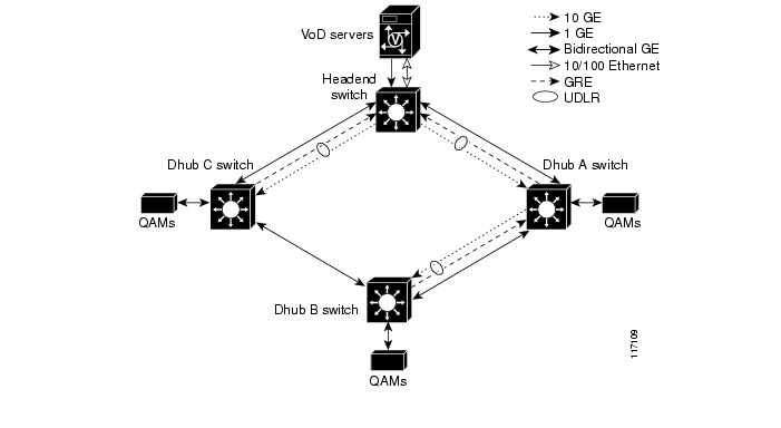
Figure 2-1 illustrates the Ethernet topology and switching components used in Release 2.0, incorporating 10-GE point-to-point and multihop connectivity, as well as a redundant bidirectional GE topology using an optical ring The network includes a point-to-point 10-GE Ethernet segment between the headend and Dhub C, as well as multihop video segments between the headend and Dhub A and Dhub B. A bidirectional 1-GE or 10-GE link between the headend switch and all the Dhub switches is used for redundant bidirectional connectivity. When 1-GE interfaces are used for the ring, unidirectional link routing (UDLR) is used to make the unidirectional 10-GE links appear bidirectional.
Figure 2-1 10-GE Point-to-Point and Multihop Video Topology
The following sections illustrate the use of Cisco ONS optical equipment to implement the design depicted in Figure 2-1.
Using the Cisco ONS 15454 MSTP
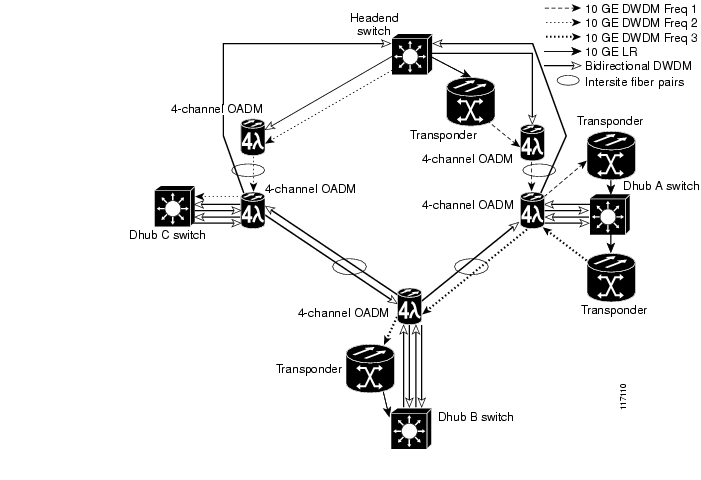
Figure 2-2 illustrates how the optical components of the Cisco ONS 15454 Multi-Service Transport Platform (MSTP) are used to implement the 10-GE topology in Figure 2-1.
Note
Here four-channel Cisco ONS 15454 optical add/drop multiplexers (OADMs) are used at the headend to multiplex DWDM wavelengths from the headend to intersite fibers routed to Dhub A and Dhub C. Four-channel OADMs are also used at each of the Dhubs to drop and return the bidirectional links going around the ring. Also, 10-GE transponders are used at the origination and termination of the 10-GE links between the headend, Dhub A, and Dhub B. The transponders convert the gray optics of the 10-GE long-reach optics in the headend and Dhub switches to and from DWDM wavelengths. The 10-GE link between the headend and Dhub C uses integrated 10-GE DWDM Cisco XENPAK optics in both the headend and Dhub switches. To save on the cost of lasers, receive-only 10-GE DWDM XENPAK optics are used in the Dhub switches.
Figure 2-2 10-GE Point-to-Point and Multihop Video Optical Topology with Cisco 15454 MSTP
Table 2-1 illustrates the Cisco ONS 15454-based optical components used for 10-GE transport in Release 2.0.
Table 2-1 Cisco 15454-Based Optical Components for 10-GE Transport
10-GE headend optics
XENPAK-10GB-SR
XENPAK-10GB-LR
XENPAK-10GB-DWDM xx.xx1
10-GE Dhub optics
XENPAK-10GB-SR
XENPAK-10GB-LR
XENPAK-10GB-DWDM RO xx.xx
10-GE bidirectional optics
XENPAK-10GB-DWDM xx.xx
1-GE bidirectional optics
DWDM-GBIC xx.xx
Transponder
15454-10T-L1- xx.xx
4-channel OADM
15454-AD-4C-xx.xx
1 The variable xx.xx represents an ITU channel between 30.33 and 60.61
Using the Cisco ONS 15216 FlexLayer
Figure 2-3 illustrates an example Cisco ONS 15216 FlexLayer-based optical topology used to implement the 10-GE topology in Figure 2-1. Unidirectional Cisco 15216 FlexLayer multiplexers are used at the headend to multiplex DWDM wavelengths from the headend to intersite fibers routed to Dhub A and Dhub C. A Cisco ONS 15216 multiplexer is also used at Dhub A to multiplex the DWDM wavelengths from the switch at Dhub A into the fiber terminating at Dhub B. To save cost, this topology uses integrated 10-GE DWDM XENPAK optics in both the headend and Dhub switches. To save on the cost of lasers, receive-only 10-GE DWDM XENPAK optics are used in the Dhub switches.
Note
Figure 2-3 10-GE Point-to-Point and Multihop Video Optical Topology with Cisco ONS 15216 FlexLayer Equipment
Table 2-2 illustrates the Cisco ONS 15216-based optical components used for 10-GE transport in Release 2.0, based on the optical topology shown in Figure 2-3.
1 Pending final release.
2 The variable xx.xx represents an ITU channel between 30.33 and 60.61.
Ethernet Topology and Components
This section presents the following major topics:
•
•
Overview
Figure 2-1 illustrates the Ethernet topology and switching components used in Release 2.0, incorporating 10-GE point-to-point and multihop connectivity, as well as a redundant bidirectional GE topology using an optical ring. As with previous releases, the switching topology consists of a headend switch and a Dhub switch, with unidirectional links between the switches. A bidirectional 1-GE or 10-GE ring between the headend switch and all of the Dhub switches is used for redundant bidirectional connectivity. UDLR is used to make the unidirectional 10-GE links appear as bidirectional interfaces.
The headend switch is connected to the streaming components of the VoD server through unidirectional or bidirectional 1-GE links, depending on the VoD server vendor. ( Table 1-3 provides details on the capabilities of VoD servers used in the this solution.) VoD servers with unidirectional links for streaming support a separate 10/100-BASE-T Ethernet link for management connectivity, connecting to a management port on the headend switch. Bidirectional 1-GE links provide the connection between the Dhub switch and the QAM gateways.
Bidirectional 1-GE links are used between the Dhub switch and the QAM devices, including a Cisco Catalyst 4500 series switch hosting Cisco uMG9850 QAM modules. (See Bidirectional Connectivity.)
Figure 2-3 lists the switching platforms and line okcards used in the Ethernet switching topology. Because not all Cisco Catalyst switches support 10-GE interfaces, the use of 10-GE in this solution limits the choice of Cisco Catalyst switches.
Table 2-3 Switching Platforms and Line Cards Used in Ethernet Switching Topology
Catalyst 6509 and Cisco 7609 with Sup 7209
WS-X6724-SFP
24-port, 1-GE optical
SFP
x
x
x3
WS-X6748-GE-TX
48-port, 1-GE electrical
N/A
x
x
WS-X6704-10GE
4-port, 10-GE optical
XENPAK-10GB-SR
x
x
XENPAK-10GB-LR
x
x
XENPAK-10GB-DWDM xx.xx4
x
x
XENPAK-10GB-DWDM-RO xx.xx
x
1 To see which VoD servers support electrical and optical interfaces, see Table 1-3.
2 To see which QAM gateways support electrical and optical interfaces, see Table 1-2.
3 Because this module does not support DWDM, it must be integrated with third-party transponders to support bidirectional 1-GE DWDM connectivity between Dhubs.
4 The variable xx.xx represents an ITU channel between 30.33 and 60.61
Ethernet Topologies
The Ethernet topologies for the 10-GE designs in Release 2.0 are similar to the "switch-in Dhub" topology in previous releases. The logical 10-GE topology is shown in Figure 2-4.
Note
http://www.cisco.com/univercd/cc/td/doc/solution/vodsols/geopt1_1/voddig/index.htmFigure 2-4 Logical Ethernet Topology
This topology breaks the video transport path into four classes of logical IP segments:
•
•
VoD Server to Headend Switch
This segment consists of all of the links between the VoD servers and the headend switch. These links are terminated by means of a MAC-layer bridge group into a single IP (VLAN) interface on the headend switch. Because these links are terminated in a single VLAN group on the headend switch, the IP addresses assigned to these links on the VoD servers should be in the same subnet.
Headend Switch to Dhub Switch
This segment consists of all the 10-GE links between a headend switch and a Dhub switch. For Dhubs that require less than 10 gigabits of bandwidth, a single 10-GE link is provisioned and a single physical Layer 3 (no switchport) interface is configured. For transports that require more than 10 gigabits of bandwidth, multiple 10-GE links are provisioned between the headend switch and the Dhub switch.
To simplify routing configurations when multiple 10-GE links are provisioned between a headend and a Dhub switch, all the links are configured as a single logical pipe at the IP routing and forwarding layer, where load-balancing techniques are used to assign individual MPEG flows to the physical links within that pipe. There are a variety of load-balancing techniques that can be used to assign MPEG flows to the member links of a logical pipe:
•
•
•
Because most headend-to-Dhub switch connections do not require more than 20 gigabits of bandwidth, the Cisco Gigabit-Ethernet Optimized VoD Solution, Release 2.0 limits load balancing to a single EtherChannel group of two ports assigned to a single physical Layer 3 (no switchport) interface.
Because of the inherently unidirectional nature of MPEG video, it is important to use physical Layer 3 interfaces as opposed to VLAN interfaces. The reason for this is that when packets are switched to an outgoing VLAN interface, they are first switched at Layer 3 using IP forwarding, and then at Layer 2 using a VLAN interface-specific bridging table. Unlike IP routing tables, which do not forward packets unless there is a routing table entry for the destination address of an IP packet, bridging tables typically flood packets until a MAC layer forwarding entry is created. For MPEG video, this flooding process could be disastrous, as it could end up causing congestion on all the physical ports assigned to the VLAN trunk. In fact, flooding is not normally an issue for VLAN interfaces, because the normal Address Resolution Protocol (ARP) process associated with bidirectional Ethernet interfaces ends up populating a MAC-layer forwarding entry for the bridging table associated with the VLAN interface. However, even with ARP, entries in a MAC-layer bridging table can be removed as a result of periodic aging processes or error conditions that may occur during normal operation. For these reasons, physical Layer 3 (no switchport) as opposed to VLAN interfaces are used in Release 2.0.
Dhub Switch to QAM Gateways
This segment consists of all the 1-GE links between the Dhub switch and the QAM gateways (either the Cisco uMG9820 or the Cisco uMG9850). For QAM gateways that require less than 1 gigabit of bandwidth (that is, the Cisco uMG9820), a single 1-GE link is provisioned and a single physical Layer 3 (no switchport) interface is configured. For QAM devices that require more than 1 gigabit of bandwidth (that is, the Cisco uMG9850 modules hosted in a Cisco Catalyst 4500 series switch), multiple 1-GE links are provisioned between the Dhub switch and those modules. These links can be configured and assigned to Layer 3 interfaces in one of two ways.
Method 1
The first method of assigning the links of a multilink Dhub-switch-to-QAM-devices segment to Layer 3 interfaces is to bundle the links into a single physical Layer 3 interface (no switchport) consisting of a single EtherChannel group of bidirectional 1-GE ports. In this type of configuration, the QAM switch is configured to allow any module to be reached from the EtherChannel interface in that switch by means of Layer 2 switching. (For more information on configuring a Cisco Catalyst 4500 series switch to support this, see Support for Embedded QAM Gateways.) To ensure optimum load-balancing efficiency, Release 2.0 limits the number of 1-GE ports that may be combined into this EtherChannel group to 2, 4, or 8 ports. While this provides limited choices in the amount of bandwidth that may be provisioned between the Dhub switch and the QAM switch, it does simplify routing configuration, becaus only a single Layer 3 interface and IP address must be configured. The main benefit of this, however, is resiliency.
In addition, when a single EtherChannel is used between the Dhub switch and a QAM switch, that EtherChannel can be configured to provide resiliency. (Instead of using a Layer 3 interface to a QAM group, another option—not tested as part of this solution—is to use a two-gigabit EtherChannel. This overprovisioning also provides resiliency.) When there is a link failure, both asymmetric and bidirectional EtherChannel rehash the flows going through a given EtherChannel to the remaining links in the bundle. If an EtherChannel group is overprovisioned so that more links are assigned to the EtherChannel group than the potential peak load can generate, then this property has the benefit that a link failure may cause no degradation of service at all. However, if the EtherChannel group is not overprovisioned, this property can negatively affect all the subscribers associated with that EtherChannel group. This is because a link failure can end up causing congestion on all of the remaining links in the EtherChannel group.
Method 2
The second method is to configure a separate physical Layer 3 interface for each link between the Dhub switch and QAM switch. If each QAM gateway were reachable from each of these links, they would appear as equal-cost links to the CEF switching layer, because the links run between the same two nodes and can reach the same sets of IP destinations (the Dhub switch and QAM devices). However, to obtain maximum efficiency when multiple links are used between a pair of nodes in Release 2.0, CEF-based IP load balancing is not recommended on the Cisco Catalyst 6509 or the Cisco 7609. Instead, each 1-GE port on the Dhub switch is configured so that only a single QAM gateway (the Cisco uMG9850) can be reached from it. This is accomplished by assigning each physical Layer 3 interface to a separate subnet, and then assigning one Cisco uMG9850 in the host switch (the Cisco Catalyst 4507 switch hosting that module) to that same subnet. To ensure that only a single Cisco uMG9850 in the QAM switch can be reached from each physical Layer 3 interface on the Dhub switch, each GE interface (port) in the QAM switch is paired with a single Cisco uMG9850 module by configuring Layer 2 switching between the GE interface in the host switch and the module, and assigning them both to a unique logical VLAN. (For more information on configuring a Cisco Catalyst 4500 series switch to support this, see Support for Embedded QAM Gateways.)
The choice of which of the above two methods is used to configure the links between the Dhub switch and a QAM switch depends on the tradeoff between ease of configuration and the flexibility of assigning bandwidth to these links.
Dhub Switch to Dhub Switch
In multihop video topologies, a fourth IP segment runs between an intermediate Dhub and either a terminal Dhub or another intermediate Dhub. Interfaces associated with this segment should be configured exactly as discussed in Headend Switch to Dhub Switch. (For more information about multihop video, see Multihop Video.)
Subtended Dhubs
Because the 10-GE configurations in Release 2.0 use optical rings, Release 2.0 supports subtended Dhubs.
Note
http://www.cisco.com/univercd/cc/td/doc/solution/vodsols/index.htmBidirectional Connectivity
Either 1-GE or 10-GE bidirectional interfaces are used between the headend and Dhubs to enable bidirectional connectivity between the headend and the Dhubs. The bidirectional GE interfaces provide the return path for the generic routing encapsulation (GRE) tunnels associated with unidirectional link routing (UDLR). UDLR makes the unidirectional 10-GE links appear to be bidirectional to protocols such as Address Resolution Protocol (ARP) and Open Shortest Path First (OSPF), which rely on having bidirectional connectivity on interfaces. The bidirectional GE interfaces may also carry video control-plane messages between set-top boxes (STBs) and control plane components located in both the Dhubs and the headend. Video control-plane protocols such as DSM-CC are used to originate movie requests from an STB and to allocate resources such as QAM channels to a VoD session. Finally, the bidirectional GE links may also carry traffic from other services such as Internet access and telephony. An Internet access service would generate traffic between Cable Modem Termination System (CMTS) aggregation routers located in Dhubs and point-of-presence (POP) routers located in the headend. A telephony service would route voice traffic originated at voice-enabled endpoints connected to the HFC network through CMTSs located in the Dhubs to VoIP gateways located in the headend or to a voice-enabled network between multiple headends. Since the bidirectional GE links may be used for many functions and services, it is important that the bidirectional GE topology be redundant. (See "Providing Redundancy and Reliability.") Redundancy for the bidirectional GE topology is often provided by running the links around a fiber-ring interface connecting the headend to a set of Dhubs.
Release 2.0 uses UDLR with the 10-GE interfaces to make them appear bidirectional to ARP, OSPF, and other protocols that rely on sending return packets on a specific interface. While UDLR allows an arbitrary IP return topology, Release 2.0 was tested with a dedicated GE return path. Asymmetric EtherChannel was not tested with the 10-GE topologies in Release 2.0, because the amount of bandwidth required from Dhub sites to the headend is typically less than 1 gigabit. An asymmetric EtherChannel uses multiple unidirectional links downstream and single bidirectional link upstream, all of which are 10-GE links.
Routing and QoS
As in the previous releases, OSPF is the routing protocol used in the solution. OSPF populates routes to the QAM gateways on the headend switch, and also enables equal-cost load balancing when multiple IP interfaces are configured between the headend and Dhub switches.
Release 2.0 enables Quality of Service (QoS) on the interfaces between the headend and Dhub switches, as well as on the interfaces between Dhub switches. For example, input access lists are enabled on the headend switch interface that is connected to the VoD servers. These access lists mark ingress traffic on the links from the VoD servers with DSCP 0b100000 (CS4), ingress traffic on links from out-of-band controllers with DSCP 0b011000 (CS3), and ingress traffic from all other external links with DSCP 0. If a management port is connected to the headend switch, all packets arriving on that port are marked with DSCP 0.
Note
Note also the following:
•
•
•
•
This configuration should allow VoD out-of-band traffic to be serviced in a timely manner, while not adversely affecting the MPEG video streams.
Out-of-Band Traffic
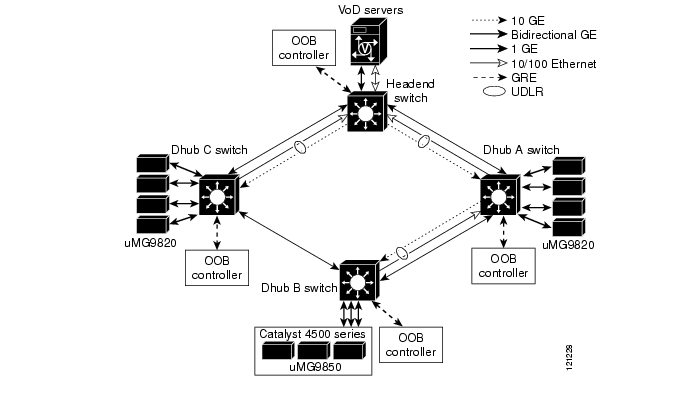
Release 2.0 also validates methods of carrying traffic associated with out-of-band (OOB) messages for VoD service. These out-of-band messages originate and terminate on STBs and various headend components such as the Cisco System Resource Manager (SRM). Since current-generation STBs do not include IP-capable interfaces such as DOCSIS (Data Over Cable Service Interface Specification), out-of-band controllers located in the Dhub act as gateways between the IP-connected components in the headend and the STBs. Figure 2-5 illustrates out-of-band traffic in the Release 2.0 topology.
Figure 2-5 Out-of-Band Traffic
Multihop Video
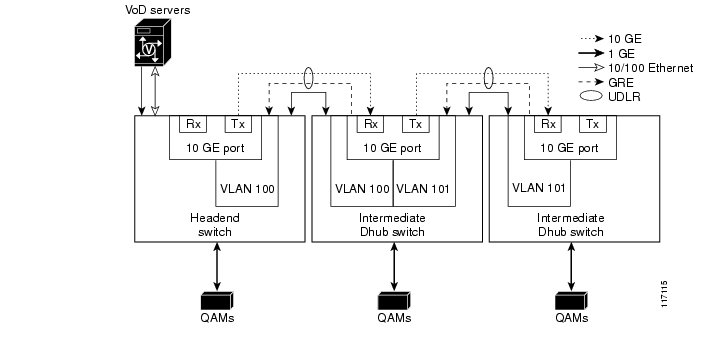
When multihop video segments are used in Release 2.0, the intermediate Dhub switches terminate one or more unidirectional 10-GE links from the upstream switch, and originate one or more unidirectional 10-GE links to the downstream switch. To save on 10-GE ports on the intermediate Dhub switches, Release 2.0 splits a 10-GE port into two logical interfaces associated with the transmit and receive optics of the 10-GE port.
Figure 2-6 illustrates the configuration to separate a physical 10-GE port on an intermediate Dhub switch into two logical interfaces. To enable the configuration of these interfaces on a 10-GE port, the port is configured as a VLAN trunk port. Two VLAN interfaces are then associated with the trunk. UDLR is enabled on each of the two VLAN interfaces to determine which interface is associated with the receive and transmit directions on the split interface. The two VLAN interfaces are then included in OSPF to enable routes to be populated on the switches dynamically.
Figure 2-6 Separating 10-GE Tx and Rx into Two Logical Interfaces
Support for Embedded QAM Gateways
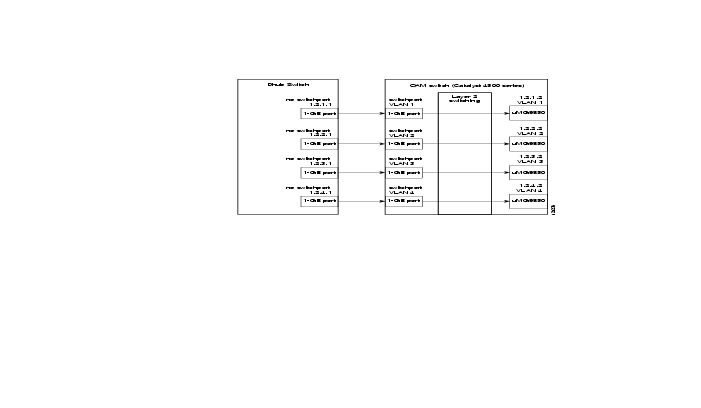
When Cisco uMG9850 QAM gateways (modules) are used in 10-GE topologies, they are hosted in a Cisco Catalyst 4500 series switch. As illustrated in Figure 2-7, the QAM (host) switch is connected to the Dhub switch through one or more 1-GE links. When the QAM switch is used in this scenario, it acts as a Layer 2 aggregation switch. The exact configuration of the Layer 2 switching on the QAM switch depends on the configuration of the Dhub-switch-to-QAM-gateway segment. As described in Dhub Switch to QAM Gateways, the 1-GE links between the QAM switch and the Dhub switch may be terminated in either (1) a single physical Layer 3 interface consisting of an EtherChannel group, or (2) multiple physical Layer 3 interfaces. The Layer 2 switching configuration of the QAM switch for each of these two alternatives is described below.
Note
http://www.cisco.com/univercd/cc/td/doc/product/cable/vod/umg9850/index.htmFigure 2-7 Configuring the Dhub and QAM Switches for Multiple Layer 3 Interfaces
Single Physical Layer 3 Interfaces
If the 1-GE links between the Dhub switch and the QAM switch are configured as single physical Layer 3 interfaces consisting of an EtherChannel group, then the QAM switch is configured so that all of the QAM gateways appear to be in the same subnet as the physical Layer 3 interface on the Dhub switch. This is done by configuring the 1-GE interfaces in the QAM switch that is connected to the EtherChannel group on the Dhub switch as an EtherChannel as well. Instead of terminating this EtherChannel in a Layer 3 interface, the EtherChannel on the QAM switch is configured as a Layer 2 (switchport) interface. The QAM gateways (Cisco uMG9850 QAM modules) in the QAM switch are each assigned an IP address in the same subnet as the physical Layer 3 interface in the Dhub switch. Finally, the QAM modules in the QAM switch are bridged to the EtherChannel in the QAM switch by assigning them to the same logical VLAN as the EtherChannel. The video route command of the Cisco uMG9850 is used to configure the QAM modules to appear in the same logical VLAN as the EtherChannel in the QAM switch.
Multiple Physical Layer 3 Interfaces
If the 1-GE links between the Dhub switch and QAM switch are configured as multiple physical Layer 3 interfaces, then the QAM switch is configured so that only a single QAM module is reachable from each incoming 1-GE interface connected to the Dhub switch. This is done by configuring each 1-GE interface on the QAM switch as a Layer 2 (switchport) interface and assigning it to the same VLAN as one of the QAM modules in the QAM switch. This sets up a MAC layer bridge table with only the QAM module and the 1-GE interface as the only interfaces associated with that table. Because of this, packets that arrive at the 1-GE interface can only be Layer-2 forwarded to the QAM module that is assigned to the same VLAN. In addition, the IP address assigned to each QAM module must appear in the same subnet as its associated physical Layer 3 interface to the Dhub switch. This is the interface on the Dhub switch that is connected to the 1-GE interface on the QAM switch that appears in the same VLAN as the QAM. Figure 2-7 illustrates the Dhub and QAM switch configuration used when multiple physical Layer 3 interfaces are configured on the Dhub switch.
Converged Multiservice Architecture
This section presents the following major topics:
•
•
Overview
Because successfully converged multiple services are supported only in a 10-GE environment, the Release 2.0 transport architecture supports the ability to implement the VoD service as part of a converged multiservice IP network. Examples of other services that may be carried in the same IP network are VoIP, residential Internet access, and broadcast video. To allow more flexible use of bandwidth among services, the IP transport architecture supports converged services at the IP packet-switching layer, as opposed to the TDM (SONET/SDH) layer or the physical (DWDM) layer.
While all services are converged at the IP packet-switching layer, each service may have different IP-topology and network-convergence requirements. For example, the VoD service requires much more bandwidth than services such as VoIP, while the VoIP service has more-stringent requirements for service availability. Because of this, the IP routing topology associated with the VoD service may be restricted to only 10-GE links and have no redundant paths for failover, while the topology associated with the VoIP service must have redundant paths between all nodes. To allow packets from different services to be routed separately, Release 2.0 uses VRF-lite as the routing and forwarding technology. (See Using VRF-lite and Differentiated Services in a Converged Multiservice Architecture.)
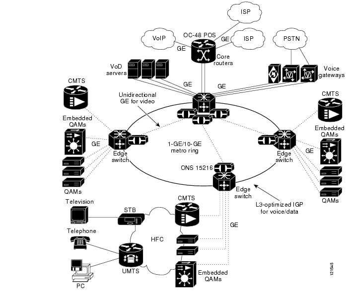
Figure 2-8 illustrates an example multiservice topology that a multiple system operator (MSO) may use to combine multiple services on a single IP-based transport infrastructure. The topology illustrates a network with a single headend and three Dhubs. The headend contains VoD servers for on-demand services, voice gateways for voice services, and links to the IP backbone as well as intercarrier connections for Internet access services. The headend includes the headend switch, which acts as the interconnection point between the headend and Dhubs for all services. The headend is connected to the Dhubs by means of 10-GE unidirectional links, as well as a 1-GE-based ring. Each Dhub contains a switch that routes traffic for all services, a CMTS for data and voice services, and QAM gateways for video services. Both the QAM gateways and the CMTS connect to the HFC plant in the Dhubs. On the other side of the HFC network, the customer premises contains a voice-enabled Universal Mobile Telecommunications System (UMTS), which terminates the voice and Internet access services, as well as one or more set-top boxes that terminate the video services.
Because the bandwidth, QoS, and availability requirements for each of these services is different, the transport network may be configured to enable each service to run on a separate logical or physical topology. For example, the traffic associated with the VoD service may be routed to the unidirectional 10-GE links, while traffic associated with the voice and Internet access services may be routed to the bidirectional ring. The directly connected 10-GE links provide the bandwidth required for the VoD service, while the bidirectional ring provides the redundancy required for the voice and Internet access services.
Figure 2-8 Multiservice Topology
Figure 2-9 illustrates a simplified multiservice architecture tested and supported by Release 2.0, with three services running in two separate routing topologies. MPEG traffic associated with video service is assigned to a video VRF table, while all other traffic is not associated with a VRF table and is therefore routed through the global routing table. For more information, see the following discussion.
Figure 2-9 Test Architecture for Multiservice Topology
Using VRF-lite and Differentiated Services in a Converged Multiservice Architecture
VRF-lite
To allow packets from different services to be routed separately, Release 2.0 uses VRF-lite as the routing and forwarding technology. [VRF stands for VPN (virtual private network) routing and forwarding.] VRF-lite allows a set of IP nodes and links to be split into multiple IP topologies. VRF-lite uses multiple instances of Interior Gateway Protocol (IGP) routing to populate a separate logical forwarding information base (FIB) for each IP topology (or VRF; the term is also used for "VPN routing and forwarding instance") configured in each router. VRF-lite supports a number of Layer 2 technologies, including Gigabit Ethernet. When multiple IP topologies run across the same physical GE link, different VLANs can be used to separate the physical link into multiple logical interfaces, each appearing in a separate VRF table.
VRF-lite can be used to create one logical topology for the VoD service and another topology for the voice and Internet access services. Because the headend components associated with each service are segregated to different logical or physical interfaces at the headend switch in Figure 2-8, traffic for each service can be managed by associating the headend switch interface connected to the components of a specific service with the appropriate VRF. This same technique can be applied to the Dhub switch interfaces connected to the QAMs used for VoD services and to the CMTS used for voice and Internet access services. Once traffic associated with different services is assigned to different VRFs, each VRF instance is considered as a separate logical topology in the routing domain. (However, it is possible to configure an interface so that it is not associated with a particular VRF. In this case, the interface is associated with the global routing table that is associated with all VRFs.) By constraining the configuration of which transport links are included in each logical topology, the network can be engineered to ensure that the physical topology associated with each logical topology meets the bandwidth, QoS, and availability requirements for each service.
Note
http://www.cisco.com/univercd/cc/td/doc/product/lan/cat4000/12_1_20/config/vrf.htmMPEG video traffic is routed through the video VRF by assigning the video links from the VoD servers and the links to the QAM gateways to the video VRF. In addition, the 10-GE unidirectional links and the associated UDLR interfaces are assigned to the video VRF. The GRE tunnels associated with the UDLR interfaces use routes installed in the global routing table. Note that because MPEG video is unidirectional and the tunnel interfaces associated with UDLR are installed in the video VRF table, there should be no traffic sent through the UDLR tunnels other than locally generated protocol messages such as ARP and OSPF. MPEG video traffic is marked for QoS treatment at the ingress interface on the headend switch.
Packets that enter the headend switch on the 1-GE interfaces attached to the VoD servers should be marked with DSCP value 32. A value of 32 corresponds to Class Selector 4 (CS4), which is Cisco's recommended DSCP value for streaming video services.
Note
Traffic associated with voice and Internet access services is not assigned to a VRF table. Because of this, routes associated with these services are installed in the global routing table. Traffic associated with these services is marked for QoS treatment at the ingress interfaces of the headend and Dhub switches. All packets that enter the headend and Dhub switches on the ports attached to voice components shown in Figure 2-9 should be marked with DSCP value 46. That value is assigned to the Expedited Forwarding (EF) per-hop behavior (PHB), which ensures that voice packets receive low-latency treatment through the network. All packets that enter the headend and Dhub switches on the ports associated with the Internet access service should be marked with DSCP value 0. DSCP value 0 is assigned to the DiffServ default class, which provides best-effort packet scheduling. DSCP value 0 is chosen for the Internet access service, because there are typically no QoS guarantees associated with residential Internet access.
A fourth traffic type associated with out-of-band messages for VoD service is supported by Release 2.0. These messages originate and terminate on STBs and various headend components, such as the Cisco System Resource Manager (SRM). Because current-generation STBs do not include IP-capable interfaces such as DOCSIS interfaces, separate out-of-band controllers are used as gateways that convert HFC-specific out-of-bound Layer 2 interfaces such as DAVIC (Digital Audio Video Council) or Aloha to standard IP Layer 2 interfaces such as Ethernet. The out-of-band controllers in the Dhub are used to forward IP packets associated with out-of-band messaging.
Out-of-band messages are marked for QoS treatment at the ingress interfaces on the headend and Dhub switches. All packets that enter the headend and Dhub switches on the ports attached to the VoD out-of-band controllers should be marked with DSCP value 24. That value is assigned to DiffServ Class Selector 3 (CS3), the DSCP value that Cisco recommends for voice and video session signaling.
Because packets from multiple services may traverse the same physical links in the multiservice topology, it is important to enable QoS on the transmit side of the unidirectional 10-GE ports, as well as on the 1-GE ports connecting the headend and Dhub switches. Table 2-4 specifies QoS treatment as well as the VRF assignment to be used for each of the traffic types in the multiservice topology. The table lists the traffic types from the multiservice topology, as well as high- and low-priority MPEG video associated with the redundancy scheme described in IP Layer Redundancy: Unequal-Cost Paths.
DSCP Features and Values Used in Release 2.0
The following is a brief summary of the basic features of DSCP:
•
•
•
•
•
Note
http://www.cisco.com/warp/public/cc/pd/iosw/prodlit/difsf_ds.htmTable 2-5 summaries the DSCP values used in Release 2.0, as well as their traffic priorities.
Table 2-5 DSCP Values and Traffic Priorities for Release 2.0
CS41
32
100000
High-priority video
AF412
34
100010
Low-priority video
EF3
46
101110
VoIP
CS3
24
011000
VoD OOB
0
0
000000
High-speed data and any other type of traffic
1 CS = Class of Service
2 AF = Assured Forwarding
3 EF = Express Forwarding
Security Considerations
VoD networks are generally closed, private networks, not subject to security attacks such as denial of service. However, it is important to ensure that the transport network used for the multiservice topology is secured from attacks. Because traffic associated with the services other than Internet access are generated by nodes considered trusted by the MSO, the likelihood of an attack being mounted from sources associated with services other than Internet access is very small. Because of this, security for the multiservice network must be focused on attacks originating from sources associated with the Internet access service and targeted at nodes associated with the VoD service.
The use of VRF-lite in the multiservice topology causes a hard separation between services in different VRF routes. VRF-lite is configured so that routes associated with the video VRF table are not shared with any other VRF or the global routing table. This means that the global routing table does not include any routes from the video VRF table. Because all VoD infrastructure nodes are connected to interfaces assigned to the video VRF table, they are unreachable from Internet-based nodes. This prevents VoD infrastructure nodes from being attacked by Internet-based nodes.
Because the bidirectional GE links are used for out-of-band communication in support of VoD and Internet access services, a denial-of-service attack from Internet-based hosts could be mounted with the goal of congesting those links and disrupting the VoD service. This form of attack is defeated by the fact that both MPEG video and VoD out-of-band traffic are marked and queued separately from Internet access traffic. The marking of packets from each service is performed by the headend and Dhub switches, which are considered trusted elements in the design.
One last form of attack considered in the multiservice topology is an attack on the headend or Dhub switches themselves. To prevent unauthorized management access of the switches through the Internet, access lists can be configured on the interfaces assigned to a global routing table. These access lists would drop Telnet, Simple Network Management Protocol (SNMP), and other requests destined to any host IP addresses of the switch.
Scaling
Scaling requirements for real-world VoD deployments can range from some 20 to 30 GEs of bandwidth on the headend (with an average of 2 to 3 GEs to each Dhub), all the way to 150-plus GEs from a single headend (with an average of 10 or 11 GEs to each Dhub). In the largest systems for initial deployments, individual Dhubs can scale from 1 GE all the way to 30-plus GEs.
In Release 2.0, systems scale to the following:
•
•
•
Table 2-6 summarizes the maximum number of simultaneous video streams supported by switch type and components.
![]()
![]()
![]()
![]()
![]()
![]()
![]()
![]()
Posted: Mon Mar 13 09:03:37 PST 2006
All contents are Copyright © 1992--2006 Cisco Systems, Inc. All rights reserved.
Important Notices and Privacy Statement.