|
|

Table Of Contents
Providing Redundancy and Reliability
IP Layer Redundancy: Unequal-Cost Paths
Providing Redundancy and Reliability
This chapter outlines the video redundancy option for the 10-GE optical transport between the headend and Dhub switches. The following major topics are presented:
•
Overview
•
Note
http://www.cisco.com/univercd/cc/td/doc/solution/vodsols/geopt1_1/voddig/index.htm
Overview
Table 4-1 lists the likely failure scenarios as well as the coverage provided by each of the redundancy options outlined in this chapter. These options are not mutually exclusive. To provide better coverage and failover times, IP and optical-layer redundancy methods may be combined.
Table 4-1 Failure Types and Redundancy Methods
Unequal-cost pathsIntersite fiber cut1
x
x
Active optical component failure
x
x
Headend switch linecard/port failure (between headend and Dhub)
x
Headend switch linecard/port failure (between headend and VoD server)
x2
x
Dhub switch linecard/port failure (between headend and Dhub)
x
Dhub switch linecard/port failure (between Dhub and QAM device)
Headend/Dhub switch linecard/port failure (bidirectional links)
x3
Headend switch failure
N/A
N/A
Dhub switch failure
N/A
N/A
1 Protection against intersite fiber cuts assumes that at least two fibers are routed between sites through diverse paths.
2 The ability to support the failover of VoD links from the headend switch depends on the capabilities of the VoD server. Only those servers listed in Table 1-3 as supporting GE failover can support redundancy for link or interface failures between the VoD server and the headend switch.
3 The ring topology associated with the bidirectional links in the 10-GE topologies of Release 2.0 inherently provides redundant paths to each node on the ring. When a failure is detected by the IGP, IP layer routing reconverges by using the alternate path around the ring.
IP Layer Redundancy: Unequal-Cost Paths
Figure 4-1 illustrates a topology in which redundancy is implemented between the headend and Dhub B through two unequal-cost paths. Dhub B is accessible through a directly connected 10-GE link from the headend, as well as by means of a multihop path through Dhub switch A.
Because the directly connected path from the headend to Dhub B has a lower cost than the multihop path, all packets from the headend to Dhub B use the directly connected path. This means that the 10-GE link from Dhub A to Dhub B is not used for video traffic originating from the headend unless the directly connected link fails.
In the event that the directly connected link fails, all traffic from the headend to Dhub B traverses the path through Dhub A. In this failure scenario, the link from the headend to Dhub A may become congested, because it is carrying traffic destined to both Dhub A and Dhub B. If the amount of video traffic from the headend to Dhubs A and B can be greater than the amount of available bandwidth on the link from the headend to Dhub A, the QoS method described below should be used to ensure that there is degradation—as opposed to a disruption—of video service.
Note
Figure 4-1 Ethernet Topology with Unequal-Cost Paths for Video
Video flows should be marked at the ingress of the links connecting the headend switch to the VoD servers. Access lists using a destination IP address and port number can be used to identify video flows routed to specific service groups or to specific QAM channels within a service group. Depending on how the access lists are configured, the service degradation can be limited either to specific service groups or to specific QAM channels within a service group. High-priority video flows should be marked with a DSCP value of 0b100000 (CS4), while low-priority video flows should be marked with a DSCP value of 0b100010 (AF41).
Two queues should be configured for video on each headend-to-Dhub-switch link (see Headend Switch to Dhub Switch). High-priority video flows marked with a DSCP value of 0b100000 (CS4) should be assigned to the priority queue, while low-priority video flows marked with a DSCP value of 0b100010 (AF41) should be assigned to a weighted queue with 60% of the available link bandwidth.
When a link failure causes congestion on the remaining link or links, the high-priority video flows in the priority queue should not be affected as long as the bundle has lost less than or equal to 50 percent of its original bandwidth. The low-priority video flows are affected only if the offered load of both high- and low-priority video is greater than the remaining bandwidth of the bundle.
Optical Redundancy
Optical-layer redundancy uses an optical splitter along with a 2 x 1 optical switch to create redundant optical paths between any two points in the network.
While optical redundancy may provide the most inexpensive form of protection, it does not provide the flexibility or level of protection that can be provided by the IP-layer redundancy schemes described above. Since optical redundancy relies on splitting an optical signal, wavelengths or fibers must be dedicated to providing a backup optical path between the nodes being protected. These wavelengths or fibers are not used unless there is a failure in the primary optical path. In contrast, the IP-layer redundancy scheme described previously allows all of the GE interfaces and the wavelengths associated with them to be fully utilized under normal operation. It then provides degraded service in the event of an outage.
In addition, optical layer protection does not provide protection against failures of packet infrastructure components such as line cards. Finally, to protect against fiber cuts, the optical wavelengths to be protected must be routed through diverse fiber paths.
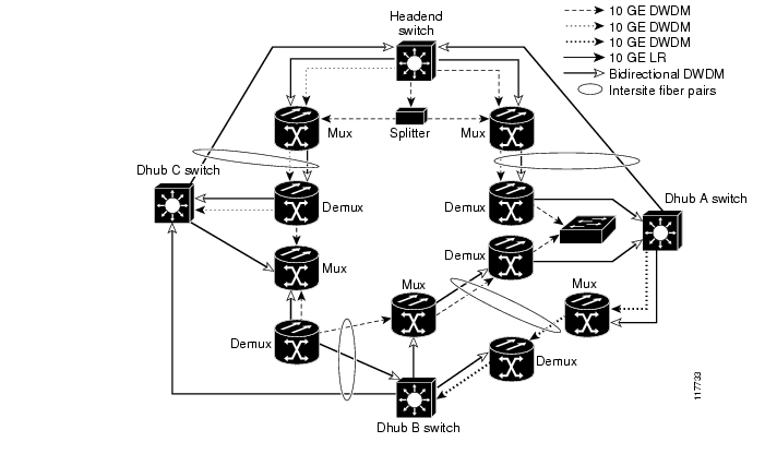
Figure 4-2 illustrates an optical topology that can be used to achieve optical layer redundancy between the headend and Dhub A. To provide redundant optical paths, the DWDM wavelength shown first in the legend is split at the headend and then sent down both directions of the ring to Dhub A. A 2 x 1 optical switch is used to select a single optical signal, which is then fed to the switch at Dhub A. Because the optical switch monitors optical signal quality, it can detect a failure and switch from working to protect inputs on the order of milliseconds. Note that the referenced DWDM wavelength that is routed counterclockwise around the ring must be sent through many passive optical components and routed through a number of Dhub sites. As a result, optical amplifiers as well as dispersion-compensation filters may be needed on the counterclockwise fiber.
Figure 4-2 Optical Redundancy
![]()
![]()
![]()
![]()
![]()
![]()
![]()
![]()
Posted: Mon Mar 13 09:03:54 PST 2006
All contents are Copyright © 1992--2006 Cisco Systems, Inc. All rights reserved.
Important Notices and Privacy Statement.