|
|

This chapter provides an introduction to Voice Network Switching. It contains the following sections:
The Voice Network Switching (VNS) application provides switched virtual circuits (SVCs) for voice or data calls over a Cisco WAN switching network. For VNS applications, the Cisco WAN switching network is typically built of Cisco IGX 8400 series wide-area switches or Cisco IPX® wide-area switches. With the VNS application in a Cisco WAN switching network, private branch exchanges (PBXs) using Digital Private Network Signaling System (DPNSS), QSIG, Q931A (Japanese ISDN), or AT&T 4ESS ISDN signaling protocols will be able to establish voice calls on demand, just as if they are dialing a public switched telephone network. Voice Network Switching will also switch calls from PBXs using Channel Associated Signaling (CAS), when it is used in conjunction with the IGX's Universal Voice Module with Model B or higher firmware, which performs CAS-to-QSIG conversion. The supported signaling protocols are all variations of the Integrated Services Digital Network (ISDN) signaling protocol. Voice Network Switching provides for the direct connection of DPNSS-, or QSIG-, or Q931A-based PBXs, reducing the need for tandem connections. In other words, with the addition of Voice Network Switching, the Cisco WAN switching network assumes many of the functions of a transit PBX, that is, tandem switching functions. This reduces the number of E1 trunks required to interconnect PBXs and enables the replacement of tandem PBXs.
A VNS network also saves network bandwidth by consolidating traffic over fewer physical interfaces, and through the use of Voice Activity Detection (VAD) and Adaptive Differential Pulse Code Modulation (ADPCM) voice compression provided by IGX/IPX switches. That is to say, a VNS network allows the use of a Cisco WAN switching network's standard voice service features to be applied to switched voice circuits from DPNSS, QSIG, Q931A, or AT&T 4ESS ISDN PBXs. Cisco's standard voice services save network resources by providing a voice compression ratio of up to 10:1.
As shown in Figure 1-1, Voice Network Switching provides a signaling mechanism to establish and maintain SVCs between PBXs across a Cisco WAN switching network. The VNS and the Cisco WAN switching network provide the network side of the ISDN user-network interface. Figure 1-1 illustrates that there is a separate signaling channel to manage the setup and disconnection of the SVC calls. The signaling channel actually stretches to the PBXs because the PBXs exchange signaling messages with the network. This signaling channel, often referred to as a D channel, is indicated by the dashed line, and can be thought of as a virtual signaling network, or signaling plane over-laid on the traditional Cisco WAN switching network. The solid line indicates the end-user traffic, the actual voice SVCs, between the two PBXs.
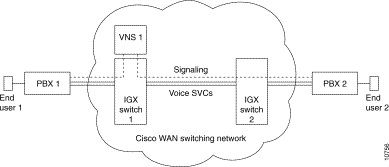
In this simple illustration, a typical call setup would follow this sequence:
Step 1 An End-User 1 at PBX 1 makes a call to End-User 2 at PBX 2.
Step 2 PBX 1 initiates a Call setup message, which is in DPNSS, QSIG, Q931A, or AT&T 4ESS ISDN format; this message is passed from IGX switch 1 to VNS 1.
Step 3 VNS 1 processes this message, including determining whether this will be a data or a voice call.
Step 4 VNS 1 instructs IGX switch 2 to build the circuit from PBX 1 to PBX 2, similar to adding a connection (addcon) for a standard network.
Step 5 When the circuit is built, IGX switch 2 passes a message to VNS 1, which relays this information to PBX 2.
Step 6 When the End User at PBX 2 answers the call, a connect message is sent from PBX 2 to VNS 1.
Step 7 VNS 1 sends a connect message to the End User at PBX 1, and the connection setup is completed.
And a typical call disconnect would follow this sequence:
Step 1 When either party hangs up, the release message is again sent from the associated PBX through the signaling channel to the attached VNS.
Step 2 The circuit is removed by the VNS which created it, and a call release message is sent to the other end user.
Step 3 After the end user acknowledges the release message, the call is cleared.
The originating VNS also generates a Call Detail Record, which includes the calling and called party numbers, call setup time and call duration. CDRs are kept in files which can be periodically collected by another host, such as the StrataView Plus (SV+) Network Management Station (NMS).
Each VNS also keeps other statistics for maintenance and diagnostic purposes.
Voice Network Switching is implemented with two or more VNS servers deployed in a Cisco WAN switching network. The VNS server, referred to simply as a VNS in this manual, is a rack-mounted adjunct processor co-located with a Cisco wide-area switch. VNS servers are always sold in redundant pairs.
The VNS comes in four models:
These models are functionally equivalent. The -E versions of the VNS are newer models that will replace older (VNS-AC and VNS-DC) versions; only -E models are being shipped at this time. The slight differences between the models will be pointed out in this documentation where it is appropriate.
The VNS is typically connected to a co-located Cisco wide-area switch (an IGX or IPX switch in this application) and is often mounted in the same rack, as shown in Figure 1-2. The VNS is connected to the Cisco wide-area switch through a Frame Relay Card, an E1 channelized Network Interface Card (E1 NIC), and an Ethernet (that is, 802.3) interface.
The redundancy feature of VNS systems are described in the section, Redundant Pairs.
Table 1-2 at the end of this chapter lists the VNS hardware and software model numbers.

VNS processors (that is, VNS servers) are installed as a redundant pair, with one active and one in the standby mode. This redundancy minimizes network downtime due to equipment failures and maintenance activity. When a switchover from the active to the standby VNS occurs, existing signaling will be switched over to the newly active unit, which will assume the same provisioning and configuration as the original active unit. The principal redundancy features are:
The VNS uses four main physical interfaces:
The VNS also supports the following application interfaces:
VNS software includes the following components:
The signaling between the VNS and the PBXs is based on ISDN variants. There are six signaling variants supported in VNS Release 3.0:
VNS Release 3.0 also supports the generic functional protocol for the control of supplementary services and additional network features as defined by ETSI specification for the QSIG protocol, ETS 300 239. The generic functional procedures are used to transport supplementary service invocations and responses from end-to-end. Acting like a transit PBX, the VNS supports related and call independent procedures, including support for the FACILITY message and Facility Information Elements.
VNS Release 3.0 consists of protocol packages: QSIG 2.1,QSIG 3.0, DPNSS 2.1, Q931A 2.1, CAS 2.2, and AT&T 4ESS ISDN, which are purchased separately. These VNS protocol packages (that is, feature software) support different sets of features. Some features are supported by all protocol packages; other features are supported by only one protocol. All the features are described in this document; where appropriate, this document will point out which software package supports the feature, and which does not. Features which are not mentioned or which were part of previous VNS (formerly DNS) releases are considered to be supported by all software packages. In Chapter 7, Understanding the VNS Command Line Interface, those menu fields which are not supported by a particular software package will be pointed out.
Table 1-1 lists the features supported by each protocol package, including which version of WAN switching switched software (IGX software) is compatible with each VNS release. The feature (or compatible switched software release) is listed in the first column. An X in the second, third, fourth columns indicates that this feature is supported by QSIG 2.1, QSIG 3.0, DPNSS 2.1, Q931A 2.1, or AT&T 4ESS ISDN. The first row of the table lists the compatible switched software release for a VNS protocol.
| Feature | QSIG 2.1 | QSIG 3.0 | DPNSS 2.1 | Q931A 2.1 | CAS 2.21 | AT&T 4ESS ISDN |
|---|---|---|---|---|---|---|
Compatible Switched Software Release | 8.2.5x | 8.2.5x or 9.1 | 8.4 | 8.2.5x | 8.5 | 8.2.5x |
Break-Out/Break-In (BOBI) | X | X | X |
|
|
|
Multi-homed E1 links | X | X | X | X | X | X |
CVM Redundancy2 | X | X | X | X | X | X |
Config Save and Restore | X | X | X | X | X | X |
Multiple Service Areas | X | X | X | X | X | X |
Hard-coded Cause Codes | X | X |
|
| X | X |
Wildcard addressing and routing | X | X |
|
| X | X |
Wildcard in translation rules |
| X |
|
|
|
|
Database integrity | X | X | X | X | X | X |
Numerical sorting of addresses | X | X | X | X | X | X |
D-Channel Preferred Routing | X | X | X | X | X | X |
D-Channel Status | X | X | X | X | X | X |
Year 2000 Compatibility | X | X | X | X | X | X |
Voice or Data CDR Records | X | X | X | X | X | X |
New CLI and other Enhancements | X | X | X | X | X | X |
Configurable Cause Codes |
| X |
|
|
|
|
Generic Functions |
| X |
|
|
|
|
| 1 CAS 2.2 is QSIG protocol designed to work with the IGX's UVM and provide CAS Voice Switching. This feature is described in Appendix I, Channel Associated Signaling Voice Switching. 2. The CVM Redundancy feature also applies to the UVM card. &&Center&& &&Center&& &&Center&& &&Center&& &&Center&& &&Center&& | ||||||
The VNS Configuration Interface is run from the VNS multitasking platform, either from a directly connected terminal or remotely through a telnet session. The VNS Configuration Interface, also known as the VNS Command Line Interface (CLI), provides a mechanism for the operator to configure the VNS and provision VNS services. Using a SNMP interface to VNS, the CLI can:
Each VNS (or redundant pair of VNSs) are assigned to control a group of one or more nodes, i.e., an IGX or IPX switch. These nodes are considered the VNS's service area (or domain). The VNS will be directly attached to one of the nodes in its area. The VNS processes call setup or release requests for calls originating in its area, or calls received from another area but destined for this one. VNS areas do not overlap. This feature is referred to as multiple domains.
The VNS exchanges heartbeat messages with all of the IGX or IPX switches in its area. The heartbeat allows the VNS to maintain a status of each node in its area. The VNS detects if a node goes out of service or returns to service.
Figure 1-3 illustrates a network with three VNS areas. Although it is not shown in the figure, the VNSs in each area will be installed as redundant pair in each area. There is VNS system, redundant pair of VNSs, serving each individual service area (or domain).
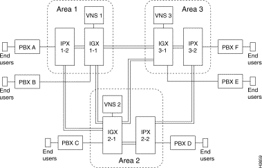
In Figure 1-3, each VNS has an IGX switch and an IPX switch in its area. VNS 1 has IGX switch 1-1 and IPX switch 1-2, and VNS 2 has IGX switch 2-1 and IPX switch 2-2, and so on. VNS 1 would exchange heartbeat messages with IGX switch 1-1 and IPX switch 1-2. Each IGX/IPX switch is connected to one PBX with its complement of end users. So in Area 1, VNS 1 would be responsible for processing call setups for all calls from PBX A and PBX B. It would also handle calls destined for PBX A and PBX B. Similarly, VNS 2 would be responsible for call setups for PBX C and PBX D, and VNS 3 would be responsible for PBX E and PBX F.
There do not have to be multiple VNS areas in a VNS network. In this case, there is only a single VNS deployed in the network. Therefore, there does not have to be a signaling overlay network, and there do not have to frame relay connections between VNSs. The VNS's Frame Relay (RS-422 to V.35 or X.21) card will not have to be connected to the node.
These messages set up, maintain, and terminate voice channel connections. They also support the operation of many PBX supplementary services or features, including calling name and number display, network call forward, network call redirect, centralized attendant, centralized voicemail, etc. These signaling protocols support a set of capabilities that are very desirable in an enterprise voice network. Cisco wide-area switches function as transit nodes for these networks, receiving call control and feature messages from PBXs via the signaling-channel connection and forwarding them across the signaling overlay network to the appropriate destination PBX.
DPNSS, QSIG, and Q931A are variants of ISDN D-channel signaling. QSIG is based on ISDN Q.921/931 standards. DPNSS is a pre-ISDN standard protocol, developed by British Telecommunication (BT) in the 1980s. QSIG was originally specified by ECMA, then was adopted by European Telecommunications Standards Institute (ETSI) and the ISO. It is becoming a world-wide standard for PBX interconnection. ETSI is also used as the name for European ISDN. Q931A is based on Japanese ISDN standards. All of these protocols (DPNSS, QSIG, ETSI, and Q931A are supported by a different signaling stack in the VNS. Thus in VNS, signaling stack refers to the particular signaling protocol to be supported by the UNI port or the VNS.)
Each E1 Network Interface Card (NIC) in an VNS server can interface with 30 signaling channels. (The second E1 NIC card in the VNS provides redundancy.)
Cisco WAN switching networks are public or private networks built around Cisco cell-switching nodes. These nodes utilize Cisco's patented FastPacket technology and/or standards-based Asynchronous Transfer Mode (ATM) and are designed to support multiple applications integrating voice, constant and variable-bit rate data, video, frame relay, and ATM services on one multimedia wide area network.
A virtual circuit only allocates a physical connection when there is data to send. The connection between two devices is set up at the start of transmission, or when the network is configured. A PVC is similar to a dedicated private line because the connection is set up on a permanent basis. Frame relay PVC standards are well defined.
The Cisco WAN Switching System Overview contains further information about Cisco WAN switching networks and frame relay circuits
Frame Relay PVCs are used in the Voice Network Switching application for the signaling channels between VNSs. Frame relay PVCs are identified by their Data Link Connection Identifier (DLCI), which identify logical connections within a shared physical channel. Network nodes normally route frames through a network based on their DLCIs. Frames with the same DLCI are associated with a single logical channel, or PVC.
On the edge of the Cisco WAN switching network, i.e., from the PBX to the network, the signaling mechanism is either DPNSS, QSIG, Q931A, or AT&T 4ESS ISDN protocol. Within the Cisco VNS network, from VNS-to-VNS and VNS-to-IGX/IPX switch, this signaling mechanism is handled by a Cisco Proprietary Network-to-Network Interface (SPNNI).
Setting up and tearing down SVCs is a complicated process. To simplify this process, we will describe the three main interfaces:
For the VNS application, the PBX connects to a Cisco wide-area switch (e.g., IGX switch) through a Channelized Voice Module (CVM), a Universal Voice Module (UVM), or an IPX's Channelized Data PAD (CDP), which terminates an E1 PRI. The E1 PRI contains both the bearer channels with user's voice or data and a D channel, the signaling channel. The bearer channels should be routed to the far-end or which ever termination point the user is trying to call. Before that can happen, the network must setup the call or calls. The signaling channel, the D channel, carries the messages to begin the call setup process.
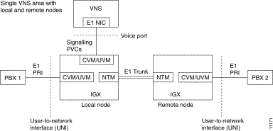
Therefore, the D channel must be routed to the VNS responsible for the node to which the PRI is connected. In Figure 1-4, there is one VNS with two nodes, local and remote, in its area. There are two PBXs, PBX 1 and PBX 2, attached to these nodes. Both of these PBXs have E1 PRI interfaces terminating on a CVM in an IGX switch. In the E1 PRI, the signaling channel, typically timeslot 16 (TS16), must be routed to the VNS over a PVC. There must be a signaling channel configured (i.e., a PVC added) for every PBX in a VNS's domain.
So in Figure 1-4, there would be two PVCs providing signaling channels to the VNS. The first would be a local connection, i.e., a DACS connection on the local node connecting the CVM connected to the PBX 1 to the CVM connected to the VNS's E1 NIC. The other signaling channel would be from the CVM on the remote node connected to the PBX 2 to the VNS E1 NIC. This PVC would be carried over the E1 trunk in Figure 1-4. (Remember an E1 NIC can manage up to 30 signaling PVCs.)
As shown in Figure 1-4, the PBX to VNS network (i.e., Cisco wide-area switch) interface is referred to as a User-to-Network Interface (UNI). This interface is also referred to as a UNI port. Both signaling channels and voice channels are carried across the UNI port. The connection between the VNS's E1 NIC and the node's CVM or UVM (or CDP in an IPX) is referred to as a Voice Port in VNS terminology.
When a call is terminated abnormally, some PBXs can re-route the call on a different trunk based on the cause code that is contained in the Disconnect, Release, or Release complete message. Often, the re-route has to be done for different disconnection causes, but PBXs can be configured to re-route on a limited set of cause codes. For this reason, the VNS provides a way to map any cause code to a different cause code. Since different PBXs use different cause codes to trigger re-routing, the cause code mapping must be done on a per-port or a PBX-type basis. The VNS creates a cause code mapping file that is associated with a specific port during configuration. This same file can be associated with all the ports connected to the same type of PBX. The file is created and edited through the VNS Configuration Interface. For more information, see Cause Code Mapping in Chapter 7.
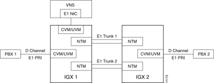
Often the UNI port is on a node which is not directly attached to the VNS doing the signaling for that area. In this case, which is illustrated in Figure 1-5, the signaling channel (that is, D channel) may be routed to the VNS by more than one path. In this example, the D channel from BPX 2 could be routed to the VNS through either E1 Trunk 1 or E1 Trunk 2. The VNS Configuration Interface allows you to configure a preferred route for the D-channel connection between the PBX (that is, UNI port) and VNS. In this example, you could configure a preferred route over E1 Trunk 1 or E1 Trunk 2. The Port Preferred Route option allows you to specify up to 9 hops in the preferred route. This option allows the network operator to avoid network congestion and to provide load balancing and resiliency across network trunks. This feature is described further in Chapter 7 in the section Configuring Preferred D Channel Routes.
In a Voice Network Switching network with multiple domains, every VNS must be able to communicate with every other VNS in the network. This full-mesh topology provides the overlaying signaling plane necessary for the network to route and deliver SVCs. This messaging plane provides flow control mechanisms, so that once a call is admitted, it will be reliably delivered to the destination. (The VNS-to-VNS interface is only required when there are multiple VNS areas.)
In Figure 1-6, VNS 1 and VNS 2 are in different areas. They each reside over their own domain. (They could have other nodes in their respective domains, but they aren't shown here.) They are both directly attached to an IGX switch through a Frame Relay Module (FRM). There must be a frame relay PVC configured between these two VNSs. When there is a Frame Relay PVC established between the two VNSs, they are considered to be locally adjacent.
The logical connection between the two VNSs, indicated by the dashed line in Figure 1-6, is considered a network-to-network interface (NNI). In a VNS network, this is a Cisco Proprietary NNI (SPNNI) protocol, and thus this connection is often referred to as a SPNNI connection. One end of this interface will be configured as the user side (user-spnni) and the other side will be configured as the network side (network-spnni). SPNNI is media (or physical layer) independent and both reliable and efficient.
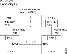
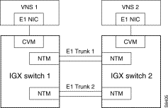
The SPNNI connection between two locally adjacent VNSs will often traverse several routing nodes which are not shown in Figure 1-6. In such a case, there will be more than one possible route between the locally adjacent VNSs. Figure 1-7 illustrates a simple case where there is more than one possible path for routing the SPNNI connection between locally adjacent VNS 1 and VNS 2. The VNS Configuration Interface allows you to configure a preferred route for the SPNNI connection between these locally adjacent VNSs. In this example, it will allow you to specify the route over E1 Trunk 1 or E1 Trunk 2. The Local Adjacency Preferred Routing option allows you to specify up to 9 hops in the preferred route. This option allows the network operator to avoid network congestion and to provide load balancing and resiliency across network trunks. This feature is described further in Chapter 7 in the section Local Adjacency Preferred Route Information.
The actual SPNNI connection between two locally adjacent VNSs is added through the VNS Configuration Interface. The VNS adds the connection as a default Frame Relay PVC. Occasionally the default Frame Relay connection default parameters will have to be modified to accommodate network traffic. Appendix G, SPNNI Operation, provides further information about modifying the Frame Relay parameters between locally adjacent VNSs.
A VNS finally must be able to communicate with the nodes, e.g., the Nodal Processor Module (NPM) in an IGX switch (or NPC in an IPX switch), in its area. (Nodal Processor Modules are commonly referred to as Network Processor Modules.) The VNS-IGX interface provides IP connectivity used for exchanging IP messages between the VNS and both local and remote nodes.
These IP based messages are exchanged for the following purposes:
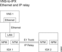
The VNS issues commands, such as build or remove a circuit, through its ethernet connection. These messages are typically between the VNS and the NPM (or NPC) and use the message network and protocols already built into Cisco WAN switching networks. When the VNS communicates with a remote node, i.e., a node in its domain to which it does not have a direct Ethernet connection, it uses IP Relay, a Cisco proprietary messaging protocol. With IP Relay, the local node, e.g., the IPX's NPC, acts as a router which relays the message, an IP packet, to the remote node's NPM. Figure 1-8 illustrates a VNS with 2 nodes in its domain. It is directly connected to IGX switch 1, and communicates with IGX switch 2 using IP Relay.
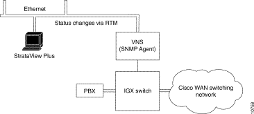
The VNS communicates with the StrataView Plus Network Management System primarily to provide status information. StrataView Plus processes and logs all traps reported by the VNS. The VNS, which receives and process traps from the IPX, uses the Cisco Robust Trap Mechanism (RTM) to send SNMP Traps to the StrataView Plus workstation. As shown in Figure 1-9, the VNS is typically connected to an StrataView Plus workstation through an Ethernet connection.
HP OpenView, running with StrataView Plus, also provides a menu option to check the status of the D-channel and SPNNI-channel signaling channels. The D-Channel Status and SPNNI-Channel Status windows are described in Appendix B, Troubleshooting.
Since the VNS processes traps, it is registered as a SNMP manager in the Cisco WAN switching network. This leaves room for 7 Cisco StrataView Plus systems in the network.
VNS icons are added through a manual configuration procedure to the StrataView Plus network topology maps. The icons can represent both the active and standby VNSs in a redundant pair. This icon shows only the existence of the VNS. The VNS icon is only visible on the StrataView Plus workstation where it was added.
StrataView Plus does not manage the VNS object. StrataView Plus does, however, receive SNMP Traps from the VNS and will display the status of the VNS with different colors as follows:
Green | Normal |
Yellow | Minor alarm |
Red | Major alarm |
Brown | VNS unreachable |
When a D channel fails or a failure is cleared, the node (IGX or IPX switch) will send SNMP traps to the VNS. The VNS processes these traps and generates a trap which it sends to StrataView Plus. (The D channel trap processing only occurs for the DPNSS protocol because the QSIG protocol already has a mechanism in place to handle D channel failures.) StrataView Plus will display the alarm and change the VNS icon color in the topology map.
The procedure for adding a VNS icon to StrataView Plus is described in Chapter 6 in the section, Adding a VNS Object to the SV+ Topology Maps.
Each VNS domain can be serviced by a VNS redundant pair, that is a VNS system. As shown in Figure 1-10, one VNS is configured as the active, the other is configured as standby. The redundant pair of VNSs are connected over an ethernet for the following functions:
The VNSs will change roles, i.e., switchover, when the active VNS is no longer in normal operation or when the network operator changes its mode through the CLI. The former case will be detected by the standby VNS missing RR Keep Alive messages from the active VNS; the later case is indicated by the SNMP SET on the VNS role MIB message received from the CLI. When a switchover occurs, existing SVC calls created by the active VNS will be cleared, PBX-to-VNS signaling PVCs will be switched over to the newly active unit, which will assume the same provisioning and configuration as was maintained by the previous active VNS.
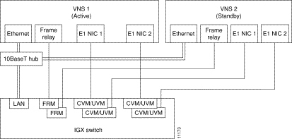
Although there are two E1 NICs installed in every VNS, they both do not have to be connected to the node. And although Figure 1-10 shows the active and the standby VNSs connected to different FRM cards, they do not have to be. They could be connected to different physical ports on the same card. (A CDP on an IPX switch has only one physical port.) The VNSs are typically connected to one another and to the node through a 10BaseT ethernet hub.
The VNS CVM redundancy feature eliminates the need for redundant CVM (or UVM) ports attached to each E1 NIC card. This feature, which is enabled or disabled in the VNS Configuration Interface, processes CVM card failure SNMP Traps from the node. When a CVM fails, the VNS receives a Trap. The VNS determines if the failed CVM is attached to a VNS E1 NIC. If the failed CVM is attached to the VNS, and the standby VNS is up and not in a failed state, the VNS will trigger a switchover to the redundant standby VNS.
Before the Voice Network Switching network can provide SVCs in response to a call from a PBX, the individual VNSs must be both configured and provisioned.
VNS configuration includes:
Provisioning, which is done mainly through the VNS Configuration Interface, a command line interface (CLI), includes the following tasks:
The VNS command line interface allows you to assign address prefixes of up to 30 digits for a VNS area, and individual addresses at a UNI port of up to 40 digits. These addresses identify the end-users participating in call attempt as the called party or calling party. These addresses are a telephone-number-like format and assigned according to the VNS-user's numbering plan.
The VNS allows the use of wildcards (*) when configuring addresses and address prefixes in a network. This simplifies addressing and speeds up call routing. In addition, a wildcard can be used to replace a pattern of digits for situations where the addresses originating from or destined to a specific port or service area require a common transformation. Wildcard addressing is described further in Chapter 7, Understanding the VNS Configuration Interface.
Configured addresses are stored as Address Information records in the VNS Database. These records are displayed in descending order with the largest numerical address displayed first. Thus an Address Information record of 8000 is displayed for 7999 which is displayed before 900, etc. There is further information about Address Information records in Chapter 7 in the section Address Information.
The VNS allows you to screen addresses, that is, filter calling party and called party numbers. Using the VNS Configuration Interface, you can create lists of calling party (source addresses) or called party (destination addresses) which you will either allow or disallow on a per-UNI-port basis. There is further information about address screening in Chapter 7 in the sections Address Screening Information and Screening Type Information.
The VNS provides address (that is, number) translation to route public network telephone numbers over a VNS private networks. This translation feature can be used to translate a public number to a private number for Break-In and a private number to a public number for Break-Out. Number translation is configured with the VNS Configuration Interface and is described further in Chapter 7 in the section Transformation Rules Information. The Break-Out/Break-In (BOBI) feature is described in this chapter in the section, Break-Out/Break-In Feature.
The VNS Configuration Interface is a series of menus that are used to configure and provision the VNS. When a menu is completed and saved, it becomes a record in the VNS database, which is stored on the VNS disk. You can use the VNS Configuration Interface to browse the database as well as to modify it.
The VNS provides a database integrity mechanism to allows you to have confidence that the VNS database is intact and uncorrupted. The database integrity mechanism uses checksums on individual records in the VNS database to detect incomplete database, a partial database, or corrupt fields in database records.
The VNS database integrity is checked during the following operations:
 | Caution Database corruption that occurs on a power failure can be corrected only by restoring the database from a backup. The database integrity mechanism will only detect such a failure; it can not prevent or recover from it. Therefore, you should perform database backups on a regular basis. The procedure for backing up your database is described in Chapter 8 in the section Saving and Restoring the VNS Database. |
In a redundant pair of VNSs, the database checksums files are also updated from the active VNS to the standby VNS along with the database.
There is further information about the VNS Configuration Interface Validate Database option in Chapter 7 in the section Validate Data Base.
Figure 1-11 illustrates a simple example of multihoming. In this case, CMV1 on IGX switch 1 and CVM2 on IGX switch 2 are multihomed to one another. Both CVM ports have been configured for the same port address, Address 100. (Although in this example both CVM ports are shown connected to the same PBX, they could be connected to separate PBXs; although this is typically not done.)

When the Far-End places a call to Address 100, the VNS will process the call. When the VNS detects a call to address 100, i.e., to a multihomed port, it will step through an algorithm to determine which CVM port to use to reach Address 100. This algorithm takes into consideration the prevailing conditions of each port and other criteria, such as:
These selection criteria are specified during the configuration of the port with the VNS Configuration Interface. The user-configurable parameters include:
UNI ports are always multihomed in pairs. If the IGX switch 1 CVM1 is multihomed with the IGX switch 2 CMV2, it implies that CVM2 is also multihomed with CVM1. But CVM2 could be independently multihomed with CVM1, using a different set of port selection criteria; therefore each pair of multihomed ports will require two records in the VNS database.
A typical use of multihoming is to multihome several ports to a single primary port. In Figure 1-12 for example, three separate ports will be multihomed to a single primary port. In this case, the primary port will be IGX switch 1 CVM1. There will be three multihomed pairs:
1. IGX 1 CVM1 is multihomed to IGX 2 CVM2
2. IGX 1 CVM1 is multihomed to IGX 3 CVM3
3. IGX 1 CVM1 is multihomed to IGX 4 CVM4
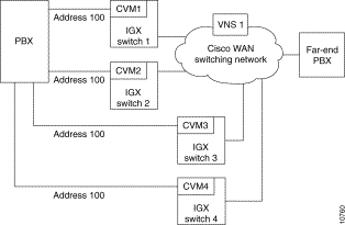
When the Far-End places a call to Address 100, the VNS will process it. After determining that it is a call to address 100, i.e., to a multihomed port, the VNS will step through an algorithm to determine which CVM port to use to reach Address 100. In this case, when determining the CMV port to route the call through, the VNS would step through all the selection criteria for each of the multihome pairs. Then it would route the call through the appropriate port.
Multihoming configuration parameters are discussed further in Chapter 7 in the sections Multihome Port Configurations and Multihome Policy Configurations.
Voice Network Switching supports the Break-Out/Break-In (BOBI) feature. BOBI allows interworking between Euro ISDN (ETSI) and DPNSS or between ETSI and QSIG. As shown in Figure 1-13, this feature allows a user connected to a DPNSS (or QSIG) PBX to call out (Break-Out) to the European public ISDN network through the Cisco WAN switching. Conversely, it also allows a user on the European public ISDN network to call in (Break-In) to a user connected to a DPNSS (or QSIG) PBX through the Cisco WAN switching. As described in the section, Address Translation, the VNS address translation feature can be used to transform public network address formats to VNS private network formats, and vice versa.
BOBI allows calls to be routed long distances using private facilities. BOBI calls can:

With the BOBI feature, there are six types of connections:
The VNS maps the DPNSS to ETSI (Euro-ISDN) according to BTNR 189I Interworking between DPNSS1 and ISDN Signaling Systems, December 1993. The VNS maps QSIG to ETSI according to ETS 300 102 and ETS 300 172.
The VNS creates and stores Call Detail Records (CDRs) for voice (or data) SVCs that it establishes. CDRs are created at the originating-end VNS once a call is set up. CDRs identify whether it is a voice or data call, the calling and called numbers, the local and remote node names, date and timestamp, elapsed time in seconds and Call Failure Class (that is, cause codes).The CDRs are stored in a file and retrieved at a fixed interval by the StrataView Plus workstation or by any server attached to the Ethernet. The VNS Configuration Interface allows you to configure CDR File Counts and CDR File Intervals which define the number of CDR files generated and the interval for which a CDR file will be generated.
There is further information about Call Detail Records in Appendix C, Call Detail Records.
If you are a network administrator and need personal technical assistance with a Cisco product that is under warranty or covered by a maintenance contract, contact Cisco's Technical Assistance Center (TAC) at 800 553-2447, 408 526-7209, or tac@cisco.com. To obtain general information about Cisco Systems, Cisco products, or upgrades, contact 800 553-6387, 408 526-7208, or cs-rep@cisco.com.
Cisco recommends that a modem be attached to the VNS to provide remote access for our Product Support and Technical Assistance Center (TAC). With an attached dial-in modem, Product Support can log in remotely and resolve potential problems. (Modem access is required during field trials of Voice Network Switching.) Appendix D contains further information about Dial-In Support.
The currently available hardware and software options of the Voice Network Switching (VNS) are listed in Table 1-2.
| VNS Model Numbers | Description |
|---|---|
VNS-AC-E (or -DC-E) | Voice Network Switching (VNS) system (newer models) |
| Voice Network Switching (VNS) Feature Software | |
VNS-SW-QSIG-2.1 | QSIG release 2.1 protocol feature |
VNS-SW-QSIG-3.0 | QSIG release 3.0 protocol feature |
VNS-SW-DPNSS-2.1 | DPNSS protocol feature |
VNS-SW-Q931A-2.1 | Q931A (Japanese ISDN) protocol feature |
VNS-SW-CAS-2.2 | VNS QSIG protocol modified to work with the IGX UVM with model B firmware (switched software release 8.5) and provide CAS Voice Switching. See Appendix I, Channel Associated Signaling Voice Switching, for details about this feature. |
| Voice Network Switching (VNS) Additional Port License | |
VNS-LIC10-PRI | CDP/CVM T1/E1 port software license--additional 10 ports |
|
|