|
|

This Troubleshooting appendix is divided into the following sections:
The Initial Troubleshooting section provides some general hints, which should help to eliminate common, easily fixed problems in a VNS WAN switching network. It also provides instructions for running the VNS Status script.
The remaining sections provide suggestions for solving specific types of problems. These sections also include details on using some specific troubleshooting tools, such as the Frame-Relay Status Utility, StrataView Plus's D-Channel and SPNNI Status windows, and a list of VNS Traps.
When you suspect a problem with a VNS network, you should:
Step 1 Begin troubleshooting with the SV+ Workstation:
Step 2 Make sure that the Clock Source is configured correctly throughout the network.
Step 3 Make sure that the signaling PVCs are built between the UNI ports (i.e., PBX's) and the VNS.
Step 4 Use the standard Cisco IGX and IPX switch command line interface and Cisco StrataView Plus troubleshooting tools (e.g., dspnw, dspalarms, tstcon, and dchst, etc.).
There is also a VNS Status script (vns_status) that provides information about the status of the VNS. This script resides in the /usr/vns directory.
To find out the VNS Status, follow these steps:
Step 1 From the UNIX prompt on the VNS, change directory to /usr/vns.
Step 2 Run vns_status.
If the VNS processes are running, the following message appears on the console:
VNS processes are active
If the VNS processes are not active, the following message appears on the console:
VNS processes are not running. Please reboot the VNS.
When there is a problem with the SV+ Workstation to VNS communication and they are connected over ethernet, the following is a list of things that you should check:
Step 1 Check the cabling between the SV+ Workstation and a router and 10Base-T hub.
Step 2 Check the cabling between the hub or router and the VNS.
Step 3 If the VNS is on a subnet, make sure the IP Address is set correctly with respect to subnet masks.
inet 127.0.0.1 netmask ff000000
inet 192.168.200.101 netmask ffffff00 broadcast 192.168.200.255
ether 8:0:20:72:5e:a7
inet 201.2.3.4 netmask ffffff00
Step 4 If the ethernet connection is through routers, make sure the routers are set up correctly.
Step 5 Check with your network system administrator to see if you need to modify SV+ Workstation's /etc/defaultrouter file to identify the router.
Step 6 Ping the SV+ Workstation from the VNS:
ping hostname of SV+ Workstation
then
ping IP address of SV+ Workstation
If you can ping with the IP address but not with the hostname, then /etc/hosts has not been set up correctly.
Step 7 Repeat Step 6, but ping from the SV+ Workstation.
There are two types of Signaling connections in a VNS WAN switching network:
The PBX to VNS takes an ISDN (either QSIG or DPNSS) D-channel from the PBX to the VNS. This channel is terminated on a VNS's E1 NIC. The VNS to VNS signaling connections are frame relay connections which terminate on the VNS's Frame Relay Card.
There are two series of tests available for the E1 NIC:
The software drivers for the E1 Network Interface Cards (E1 NICs) can be tested in loopback mode. But it requires an external loopback connection.
To run the loopback tests for the E1 NICs, follow these steps:
Step 1 Connect the TX BNC connector to the RX BNC connector on one or both E1 NICs. Check that the Green LED on the back of the E1 NIC lights to indicate that the link is active and in sync. (If the Green LED does not light, the E1 NIC is bad.)
Step 2 Using a directly connected terminal (or with a Telnet connection), change your working directory with the following command:
cd /opt/CoE1DRV/bin
There are two loopback programs in this directory:
txrx used to run a loopback over a single specified channel.
thtxrx to run a loopback over multiple channels.
Step 3 To run txrx, Enter:
./txrx -s <unit number> -b <channel number> -l <packet size>
The number of successfully received packets will be updated on the screen periodically with sequence error indication.
Step 4 To run thtxrx, Enter:
./thtxrx -s <unit number> -b <start channel num> -n <number of channels>
If there is only one E1 NIC in your VNS, then it is not necessary to specify the unit number.
The E1 NIC diagnostics (coe1diag) tests the E1 card at a specified VNS slot thoroughly. All channels are separately tested with data packets varying from 2 to 200 packets. Then all channels are tested simultaneously. The E1 NIC diagnostics program prints a summary of the test results at an attached terminal.
To run E1 NIC diagnostics (coe1diag), follow these steps:
Step 1 Using a directly connected terminal (or with a Telnet connection), change your working directory with the following command:
cd /opt/CoE1DRV/bin
Step 1 Enter:
./coe1diag [-s] [-e] [-l]
The coe1diag command has the following options:
-s <slot number> which is the VNS SBus slot number and is required only there is more than one E1 NIC card in your unit.
-e exit on error. Normally the program terminates only after carrying out the tests. With this option, the test terminates after detecting the first error on the card.
-l internal loopback mode which enables the E1 NIC to be tested without the external loopback connection. In this mode, the transmitted data is looped back to the receiver internally on the E1 NIC.
HP OpenView running on the Cisco StrataView Plus Workstation contains two options to check the status of VNS signaling connections:
To open check the status of a VNS's signaling connections, follow these steps:
Step 1 At the SV+ Workstation, if HP Openview is not running, open an HP OpenView window:
Step 2 Double click on your network icon to open a Network Topology window and map, as shown in Figure B-1. There are two VNS icons, babylon and nineveh, on this sample Network Topology
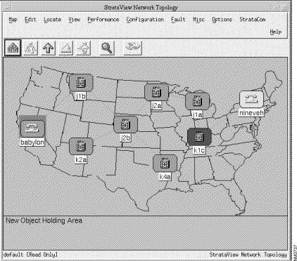
Step 3 Select the VNS icon for which you want to check the signaling connections. (In Figure B-1, babylon is highlighted as having been selected.)
Step 4 Pull down the StrataCom menu as shown in Figure B-2.
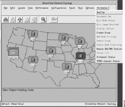
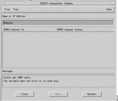
Step 5 Select either D-Channel Status or SPNNI Status. If you select D-Channel Status the D-Channel Status window shown in Figure B-3 appears. If you select SPNNI-Channel Status, the SPNNI-Channel Status window shown in Figure B-4 appears.
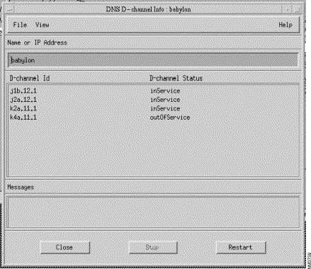
As shown, the D-Channel Status window lists the D-channel Id (node.slot.port) and its status. Note that the D-channel Id lists the physical port and not the logical port or timeslot of the D-channel.
The Restart button performs another SNMP GET request to refresh the screen. The View button allows you to sort the contents of the window by column. HP OpenView contains help menus that clearly explain these window functions.
This section contains some generic hints for troubleshooting the frame relay PVCs that the VNSes use to communicate with one another. (Note that these connections are used for multiple VNS areas, and are not required for a single domain.)
When there appears to be a problem with an existing PVC, try these things:
1. Use the dspportstats command to see if frames are being passed across the port. Reset the port stats counters with the clrportstats command. Look for frame errors. (The Cisco WAN Switching Command Reference publication describes this command in detail.)
2. Use the dspchstats command at both endpoints of the PVC. Reset the channel stats counters to the clrchstats command. (The Cisco WAN Switching Command Reference publication describes this command in detail.)
3. Use the Frame Relay Status Utility on the VNS to verify data on the PVC, identified by its DLCI, at the VNS. (The next section describes Using the Frame Relay Status Utility.)
4. Ensure that the factory-configured file /usr/net/fr/ fr_config file appears as it is shown in Chapter 6.
5. Ensure that the /usr/net/fr/fr_conv file contains the IP address to DLCI mapping for any IP networks accessible across the frame relay network, as shown in Chapter 6.
The Frame Relay Status Utility runs on the VNS and monitors the frame relay connections over the serial frame-relay port (RS422/V.35).
To use the Frame Relay Status Utility, follow these steps:
Step 1 Log into the VNS as root.
Step 2 Change directory to /usr/net/fr.
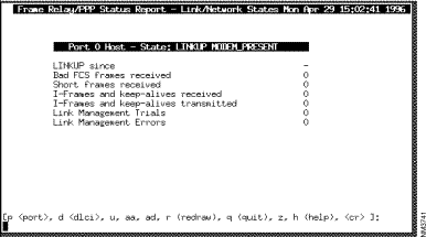
Step 3 Type frstatus and press Enter. The Frame Relay/PPP Status Report screen appears, as shown in Figure B-5.
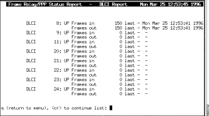
Step 4 Type ad and press enter to get a list of all the currently configured DLCIs. A DLCI Report screen, shown in Figure B-6, appears:
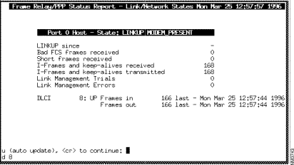
Step 5 Find the DLCI you wish to monitor and press q. You will return to the previous screen. Type d, followed by a space, then the number of the DLCI, and press Enter. A Frame Relay/PPP Status Report screen, shown in Figure B-7, which includes Frames-in and Frames-out counters for the specified DLCI, will appear:
Step 6 To clear the Frames-in and Frames-out counters, press Enter, the q, and you will return to the VNS UNIX file directories. Type frroute and press Enter.
Step 7 To return to the Frame Relay Status Utility, type frstatus and press Enter. Type z and press Enter to zero the other Frame Relay Status counters.
Step 8 Type d, followed by a space, then the number of the DLCI, and press Enter. The Frame Relay Status Report screen will appear with all counters zeroed.
Step 9 Type u 1, to update the screen at one second intervals. Observe the seconds indicators in the current time at the top of the screen are incrementing. This screen is now being refreshed and you can observe the counters to detect what is happening on the selected DLCI.
Step 1 If the handset is lifted, but there is no dial tone:
Step 2 If you have dial tone at the handset, but can not complete a call:
VNS Error messages are SNMP Traps sent from the VNS to the SV+ Workstation. Each trap usually has a number associated with a corresponding value in the INS Management Information Base (MIB). Traps can have a severity of either, clear, minor, or major. Table B-1 lists and describes the VNS Traps.
| Trap | Description |
|---|---|
coldStart | Standard SNMP Trap generated whenever the VNS is powered on. |
insStartUpTrap | Generated whenever the VNS is started up. It indicates the current status and role of the INS. |
insStatusTrap | Generated when the VNS status changes or whenever a new SNMP Manager comes in and registers for traps with the VNS. It indicates the current status of the VNS. |
insRoleTrap | Generated whenever the role of the VNS in the redundant VNS pair changes. It indicates the new role of the VNS. |
insNodeStateTrap | Generated when the VNS detects a change in the state of a node. The VNS determines that a node has gone out of service if it loses heartbeat with the node and it determines that a node has come back into service if it regains heartbeat with the node. |
insPortDownTrap1 | Generated when the VNS loses connection to a UNI port (i.e., a port connected to a PBX). |
insSPNNIDownTrap | Generated when the SPNNI connection between two adjacent VNS nodes goes down. It indicates the name of the adjacent VNS to which the connection has been lost. |
insAddrConfigFailTrap | Generated when the VNS fails to configure an address added by SV+ into operation of a port. |
insNetAddrConfigFailTrap1 | Generated when the DNÍ fails to configure a network address added by SV+ into operation on a port. |
insScreenTypeConfigFailTrap1 | Generated when the VNS fails to configure screening on a port to operate according to the specified type. |
insScreenConfigFailTrap1 | Generated when the VNS fails to configure a screen added by SV+ into operation on a port. |
insTransConfigFailTrap1 | Generated when the VNS fails to configure a transformation rule added by SV+ into operation on a port. |
insSPNNIUpTrap | Generated when the SPNNI connection between two adjacent VNSes comes up. It indicates the name of the adjacent DSN to which the connection has been regained. |
insDchannelDownTrap | Generated whenever the D-channel for a port goes down. |
insDchannelUpTrap | Generated when the D-channel for a port comes back up. |
insAlarmStatusChanged-Trap | Generated when the insAlarm Status object changes. |
| 1These traps are not currently used. |
Cause Codes are coded messages passed from a PBX to the VNS to indicate why a switched connection cannot be made. Cause Codes are included in Call Detail Records (see Appendix C) or they can be seen with a protocol analyzer capturing the message traffic between a PBX and the VNS. The following sections describe the Cause Codes for the QSIG or DPNSS protocols:
Table B-2 lists the set of Cause Codes that are applicable to ISDN-related calls. The ISDN-related cause codes are returned by the QSIG, JISDN (Q931A), EISDN (European ISDN, also referred to as ETSI), and AT&T 4ESS ISDN protocols. The table lists each Cause Code by number, then provides a textual description and explanation. Cause Codes are divided into the following classes within the table:
| Cause Code | Description |
|---|---|
| Normal Class | |
1 | Unallocated (unassigned) number This cause indicates that the called party cannot be reached because, although the called party number is in a valid format, it is not currently allocated (assigned). |
2 | No route to specified transit network (national use) This cause indicates that the equipment sending this cause has received a request to route the call through a particular transit network which it does not recognize. The equipment sending this cause does not recognize the transit network either because the transit network does not exist or because that particular transit network, while it does exist, does not serve the equipment which is sending this cause. This cause is supported on a network-dependent basis. |
3 | No route to destination This cause indicates that the called party cannot be reached because the network through which the call has been routed does not serve the destination desired. This cause is supported on a network-dependent basis. |
4 | Send special information tone This cause indicates that the called party cannot be reached for reasons that are of a long term nature and that the special tone should be returned to the calling party. |
5 | Misdialled trunk prefix (national use) This cause indicates the erroneous inclusion of a trunk prefix in the called party number. |
6 | Channel unacceptable This cause indicates that the channel most recently identified is not acceptable to the sending entity for use in this call. |
7 | Call awarded and being delivered in an established channel This cause indicates that the user has been awarded the incoming call, and that the incoming call is being connected to a channel already established to that user for similar calls (e.g., packet-mode X.25 virtual calls. |
8 | Pre-emption This cause indicates that the call is being preempted. |
9 | Preemption - circuit reserved for reuse This cause indicates that the call is being preempted and the circuit is reserved for reuse by the preempting exchange. |
16 | Normal call clearing This cause indicates that the call is being cleared because on of the users involved in the call has requested that the call be cleared. Under normal situations, the source of this cause is not the network. |
17 | User busy This cause is used to indicate that the called party is unable to accept another call because the user busy condition has been encountered. This cause value may be generated by the called user or by the network. In the case of user determine user busy, it is noted that the user equipment is compatible with the call. |
18 | No user responding This cause is used when a called party does not respond to a call establishment message with either an alerting or connection indication within the prescribed period of time allocated. |
19 | No answer from user (user alerted) This cause is used when the called party has been alerted but does not responded with a connect indication within a prescribed period of time. Note ---This cause is no necessarily generated by Q.931 procedures buy may be generated by internal network timers. |
20 | Subscriber absent This cause value is used when a mobile station has logged off, radio contact is not obtained with a mobile station or if a personal telecommunication user is temporarily not addressable at any user-network interface. |
21 | Call rejected This cause indicates that the equipment sending this cause does not wish to accept this call, although it could have accepted the call because the equipment sending this cause is neither busy nor incompatible. This cause may also be generated by the network, indicating that the call was cleared due to a supplementary service constraint. The diagnostic field may contain additional information about the supplementary service and reason for rejection. |
22 | Number changed This cause is returned to a calling party when the called party number indicated by the calling party is no longer assigned. The new called party number may be optionally be included in the diagnostic field. If a network does not support this cause value, cause No. 1, unallocated (unassigned) number shall be used. |
26 | Non-selected user clearing This cause indicates that the user has not been awarded the incoming call. |
27 | Destination out of order This cause indicates that the destination indicated by the user cannot be reached because the interface to the destination is not functioning correctly. The term "not functioning correctly" indicates that a signaling message was unable to be delivered to the remote party; e.g., a physical layer or data link layer failure at the remote party, or user equipment off-line. |
28 | Invalid number format (address incomplete) This cause indicated that the called party cannot be reached because the called party number is not in a valid format or is not complete. Note: This condition may be determined: ---immediately after reception of an ST signal; or ---on time-out after the last received digit. |
29 | Facility rejected This cause is returned when a supplementary service requested by the user cannot be provided to the network. |
30 | Response to STATUS ENQUIRY This cause is included in the STATUS message when the reason for generating the STATUS message was the prior receipt of a STATUS ENQUIRY message. |
31 | Normal, unspecified This cause is used to report a normal event only when no other cause in the normal class applies. |
| Resource unavailable class | |
34 | No circuit/channel available This cause indicates that there is no appropriate circuit/channel presently available to handle the call. |
38 | Network out of order This cause indicates that the network is not functioning correctly and that the condition is likely to last a relatively long period of time; e.g., immediately re-attempting the call is not likely to be successful. |
39 | Permanent frame mode connection out-of-service This cause is included in a STATUS message to indicate that a permanently established frame mode connection out-of-service (e.g., due to equipment section failure) (See Annex A/Q.933). |
40 | Permanent frame mode connection operational This cause is included in a STATUS message to indicate that a permanently established frame mode connection is operational and capable of carrying user information (see Annex A/Q.933). |
41 | Temporary failure This cause indicates that the network is not functioning correctly and that the condition is not likely to last a long period of time; e.g., the user may wish to try another call attempt almost immediately. This cause code may occur when the node (IGX or IPX switch) is short on resources. |
42 | Switching equipment congestion This cause indicates that the switching equipment generating this cause is experiencing a period of high traffic. |
43 | Access information discarded This cause indicates that the network could not deliver access information to the remote user as requested, i.e., user-to-user information, low layer compatibility, high layer compatibility, or sub-address, as indicated in the diagnostic. |
44 | Requested circuit/channel not available This cause is returned when the circuit or channel indicated by the requesting entity cannot be provided by the other side of the interface. |
46 | Precedence call blocked This cause indicates that there are no preemptable circuits or that the called user is busy with a call of equal or higher preemptable level. |
47 | Resource unavailable, unspecified This cause is used to report a resource unavailable event only when no other cause in the resource unavailable class applies. |
| Service or option unavailable class | |
49 | Quality of Service not available This cause is used to report that the requested Quality of Service, as defined in Recommendation X.213, cannot be provided (e.g., throughput or transit delay cannot be supported). |
50 | Requested facility not subscribed This cause indicates that the user has requested a supplementary service which is implemented by the equipment which generated this cause, but the user is not authorized to use. |
53 | Outgoing calls barred within CUG This cause indicates that although the calling party is a member of the CUG for the outgoing CUG call, outgoing calls are not allowed for this member of CUG. |
55 | Incoming calls barred within CUG This cause indicates that although the called party is a member of the CUG for the incoming CUG call, incoming calls are not allowed to this member of the CUG. |
57 | Bearer capability not authorized This cause indicates that the user has requested a bearer capability which is implemented by the equipment which generated this cause but the user is not authorized to use. |
58 | Bearer capability not presently available This cause indicates that the user has requested a bearers capability which is implemented by the equipment which generated this cause but is not available at this time. |
62 | Inconsistency in designated outgoing access information and subscriber class This cause indicates that there is an inconsistency in the designated outgoing access information and subscriber class. |
63 | Service or option not available, unspecified This cause is used to report a service or option not available when no other cause in the service or option not available class applies.
|
| Service or option not implemented class | |
65 | Bearer capability not implemented This cause indicates that the equipment sending this cause does not support the bearer capability requested. |
66 | Channel type not implemented This cause indicates that the equipment sending this cause does not support the channel type requested. |
69 | Requested facility not implemented This cause indicates that the equipment sending this cause does not support the requested supplementary service. |
70 | Only restricted digital information bearer capability is available (national use) This cause indicates that the calling party has requested an unrestricted bearer service but that the equipment sending this cause only supports the restricted version of the requested bearer capability. |
79 | Service or option not implemented, unspecified This cause is used to report a service or option not implemented event only when no other cause in the service or option not implemented class applies. |
| Invalid message (e.g., parameter out of range) class | |
81 | Invalid call reference value This cause indicates that the equipment sending this cause has received a message with a call reference which is not currently in use on the user-network interface. |
82 | Identified channel does not exist This cause indicates that the equipment sending this cause has received a request to use a channel not activated on the interface for a call. For example, if a user has subscribed to those channels on a primary rate interface numbered from 1 to 12 and the user equipment or the network attempts to use channels 13 through 23, this cause is generated. |
83 | A suspended call exists, but this call identity does not This cause indicates that a call resume has been attempted with a call identity which differs from that in use for any presently suspended call(s). |
84 | Call identity in use This cause indicates that the network has received a call suspended request containing a call identity (including the null call identity) which is already in use for a suspended call within the domain of interfaces over which the call might be resumed. |
85 | No call suspended This cause indicates that the network has received a call resume request containing a call identity information element which presently does not indicated any suspended call within the domain of interfaces over which calls may be returned. |
86 | Call having the requested call identity has been cleared This cause indicates that the network has received a call resume request containing a call identity information element indicating a suspended call that has in the meantime been cleared while suspended (either by network timeout or by the remote user). |
87 | User not member of CUG This cause indicates that the called user for incoming CUG call is not a member of the specified CUG or that the calling user is an ordinary subscriber calling a CUG subscriber. |
88 | Incompatible destination This cause indicates that the equipment sending this cause has received a request to establish a call which has low layer compatibility, high layer compatibility, or other compatibility attributes (e.g., data rate) which cannot be accommodated. |
90 | Non-existent CUG This cause indicates that the specified CUG does not exist. |
91 | Invalid transit network selection (national use) This cause indicates that a transit network identification was received which is of an incorrect format as defined in Annex C/Q.931. |
95 | Invalid message, unspecified This cause is used to report an invalid message event only when no other cause in the invalid message class applies. |
| Protocol error (e.g., unknown message) class | |
96 | Mandatory information element is missing This cause indicates that the equipment sending this cause has received a message which is missing an information element which must be present in the message before the message can be processed. |
97 | Message type non-existent or not implemented This cause indicates that the equipment sending this cause has received a message with a message type it does not recognize either because this is a message not defined or defined by not implemented by the equipment sending this cause. |
98 | Message not compatible with call state or message type non-existent or not implemented This cause indicates that the equipment sending this cause has received a message that the procedures do not indicate this is a permissible message to receive while in the call state, or a STATUS message was received indicating an incompatible call state. |
99 | Information element/parameter non-existent or not implemented This cause indicates that the equipment sending this cause has received a message which includes information element(s)/parameter(s) not recognized because the information element identifier(s)/parameter(s) are not defined or are defined but not implemented by the equipment sending the cause. This cause indicates that the information element(s)/parameter(s) were discarded. However, the information element is not required to be present in the message in order for the equipment sending the cause to process the message. |
100 | Invalid information element contents This cause indicates that the equipment sending this cause has received an information element which it has implemented; however, one or more fields in the information element are coded in such a way which has not been implemented by the equipment sending this cause. |
101 | Message not compatible with call state This cause indicates that a message has been received which is incompatible with the call state. |
102 | Recovery on timer expiry This cause indicates that a procedure has been initiated by the expiry of a timer in association with error handling procedures. |
103 | Parameter non-existent or not implemented - passed on (national use) This cause indicates that the equipment sending this cause has received a message which includes parameters not recognized because the parameters are defined not implemented by the equipment sending the cause. The cause indicates that the parameter(s) were ignored. In addition, if the equipment sending this cause is an intermediate point, then this cause indicates that the parameter(s) were passed on unchanged. |
110 | Message with unrecognized parameter discarded This cause indicates that the equipment sending this cause has discarded a received message which includes a parameter that is not recognized. |
111 | Protocol error, unspecified This cause is used to report a protocol error event only when no other cause in the protocol error class applies. |
| Interworking class | |
127 | Interworking, unspecified This cause indicates that there has been interworking with a network which does not provide causes for actions it takes. Thus, the precise cause for a message which is being sent cannot be ascertained. |
Table B-3 lists the DPNSS-related cause codes. For each code, the table lists the mnemonic, the clearing or rejection cause, the meaning of the code, and the hexadecimal value associated with the code.
| Mnemonic | Clearing/Rejection Cause | Meaning | Hex Value |
|---|---|---|---|
AB | Access Barred | Used when a particular caller is barred access to outgoing routes. | 29H |
ACK | Acknowledgment | Used to inform the Requesting PBX that the Supplementary Service has been (or is being) carried out. | 14H |
AI | Address Incomplete | Used when insufficient address digits have been received to achieve a valid address, unless conflict dialing is permitted. Where conflict dialling is permitted, NU shall be used. | 01H |
BY | Busy | Used when the called party is engaged on a call. | 08H |
CHOS | Channel Out of Service | Used to reject a call received on a channel which is out of service or uninstalled. | 23H |
CNR | DTE Controlled Not Ready | Used when the called X.21 terminal is in the "controlled not ready" state. | 2DH |
CON | Congestion | Used when PBX equipment or suitable routes are busy. | 07H |
CT | Call Termination | Used when a party releases a call by clearing in the normal way. | 30H |
FNR | Facility Not Registered | Used when a PBX receives a request relating to a service where previous knowledge of its existence is necessary, but that knowledge does not exist (e.g., a Call Back When Free call made to a PBX with no record of original registration. | 18H |
ICB | Incoming Calls Barred | Used when the called party is barred to incoming calls. | OAH |
INC | Service Incompatible | Used when the route available does not conform to the required SIC. | 13H |
MNU | Message Not Understood | Used when rejecting an unrecognized message on an idle channel. Note that the channel on which MNU was received may not be the one on which the unrecognized message was detected because Transit PBXes pass on Clearing Causes unchanged. | 1AH |
NAE-E | Network Address Extension-Error | Used to inform the Requesting PBX that a call has been rejected because of failure to process the received NAE data. | 1EH |
NT | Network Termination | Used when the call is released by the network for any reason (e.g., due to a timeout expiring or service interactions). | 02H |
NU | Number Unobtainable | Used when the Destination Address is invalid (i.e., spare). | 00H |
PFR | Priority Force Release | Used when an authorized intruding party forces the release of an unwanted party, e.g., an operator or a party with the required Breakdown Capability. | 24H |
REJ | Reject | Used when the requesting or requested party of a Supplementary Service rejects the service (e.g., Wanted party rejects a Call Offer request). | 19H |
ROS | Route Out of Service | Used when all suitable routes are out of service. | 1CH |
SI | Subscriber Incompatible | Used when the called party does not conform to the requested SIC. | 04H |
SNU | Signal Not Understood | Used when rejecting message contents which have not been understood. This CC is accompanied by the string SNU which either identifies a String which has not been understood or indicates another reason for not understanding the message (e.g., syntax error). | 15H |
SNV | Signal Not Valid | Used only when a PBX working to Issue 1 of DPNSS 1 rejects a Supplementary Information String that is invalid. | 16H |
SOS | Subscriber Out of Service | Used when the called party is out of service. | 09H |
SSI | Signaling System Incompatible | Used when the requested Supplementary Service is not supported by the route available, and there is no other suitable route. | 1BH |
STU | Service Temporarily Unavailable | Used when the requested Supplementary Service is available on the PBX, but cannot be provided at the moment. | 17H |
SU | Service Unavailable | Used when the requested Supplementary Service is supported by the PBX, but not by the called party. This Clearing Cause is accompanied by the String SU which identifies the service being rejected. | 03H |
TRFD | Transferred | Used (by Issue 2 and Issue 3 PBXes only) to instruct the Branching PBX of a 3-party call to connect together the two remaining parties. | 1DH |
UNR | DTE Uncontrolled Not Ready | Used when the called X.21 terminal is in the "Uncontrolled Not Ready" state. | 2EH |
A special file is included with the VNS software that allows five commonly used cause codes to be mapped to a single code. With the inclusion of this file, Cause Codes 2, 3, 38, 41, and 42 are all mapped to Code 34. Code 34 is then passed to PBX's attached to the VNS WAN switching network. This allows the PBX to reroute a call across a public switched network if there is a failure in the Cisco VNS WAN switching network. Call Customer Service for further information.
The VNS allows you configure specific cause codes to be returned to a PBX on a per-port basis. To find out more information about this cause code mapping, refer to the section Cause Code Mapping in Chapter 7.
|
|