|
|

This chapter describes making the interface connections between a VNS and the Cisco wide-area switch (IGX or IPX switch) and the Cisco StrataView Plus workstation. It includes the following sections:
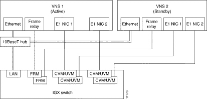
After you have rack mounted the VNS and connected the power, you must connect the physical interfaces to it. These interfaces, which are shown in Figure 6-1, are:

Figure 6-1 illustrates the VNS directly connected to an IGX switch. With an IGX switch, the Frame Relay Card is connected to an IGX's FRM, and the E1 NICs are connected to an CVM or UVM cards. If the directly connected node is an IPX switch, the Frame Relay Card would be connected to an FRP (Frame Rely PAD), and the E1 NICs would be connected to CDPs (Channelized Data PADs).
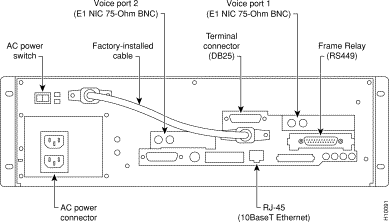
Figure 6-2 shows the location of the interface connectors for VNS-AC-E physical interfaces; the interface connectors are in the same location on a VNS-DC-E model.
You can attach a terminal (or PC running a terminal emulation program, such as ProCom), to the VNS to perform some of the configuration locally.
Attach your terminal cable, typically a null modem cable, to the A/B (Terminal) connector on the VNS's back panel, as shown in Figure 6-2. This is an asynchronous ttya port on the UNIX-based VNS. Your terminal or PC and emulation software must be set to match the VNS's communication parameters:
 | Caution A terminal (or PC) which has been connected to a VNS Terminal port should not have its power recycled because this can cause the VNS to enter a different mode. |
The VNS terminal port has been set up at the factory. If you have trouble displaying VNS files and menus cleanly, you might reset the following parameters:
stty rows 24

stty erase ^h

setenv TERM vt100
Also if you are connected to the VNS through an XTERM session, you should run the following command:
eval `resize' or resize
This lets XTERM know about the number of rows and columns.
The E1 NICs (Channelized E1) connect to either an IGX's CVM with a BC-E1 back card, or UVM BC-UVI-2E1EC backcard, or an IPX's CDP with a BC-E1 back card. Each E1 NIC has two 75-ohm BNC connectors, one for transmit and one for receive, as shown in Figure 6-3. (Figure 6-2 illustrates which E1 NIC is referred to as Voice Port 1 and which is referred to Voice Port 2.)
To connect an E1 NIC to the node, follow these steps:
Step 1 Determine which physical port on the node is considered Voice Port 1. This port will be connected to Voice Port 1 on the VNS as shown in Figure 6-2.
Step 2 Connect a 75-ohm coax cable from the transmit (TX) connector on the VNS's E1 NIC to the RX (receive) connector on the node's CDP/CVM/UVM BC-E1 card.
Step 3 Connect a 75-ohm coax cable from the receive (RX) connector on the VNS's E1 NIC to the TX (transmit) connector on the node's CDP/CVM/UVM BC-E1 card.
Step 4 If both E1 NICs are being connected to the node, repeat Steps 1 to 3 for Voice Port 2 and the second E1 NIC in you VNS.

The Voice Port on the node is either a IGX's CVM (or UVM) or a IPX's CDP. These cards must be upped and configured, with the upcd (up card), upcln (up circuit line), and cnfcln (configure circuit line) commands, like any other card on the IGX or IPX switch. You can find detailed descriptions of the IGX's or IPX's command line interface in the Cisco WAN Switching Command Reference.
At the node (i.e., IGX/IPX switch), the circuit line between the node and the VNS should be configured with the cnfcln (configure circuit line) command for:
Figure 6-4 illustrates a typical IGX cnfcln menu with the parameters set for connecting to a VNS E1 NIC. (This example is for a CVM card, a UVM card will have a similar configuration.) Note that the percent of fast modem should always be configured as 100%.
The signaling channels over this physical interface are configured through the VNS command line interface, covered in Chapter 7, Understanding the VNS Configuration Interface, and Chapter 8, VNS Network Operation.
supigx1        TN    StrataCom       IGX 16    8.4.15    Feb. 22 1998 16:17 GMT

CLN 8 Configuration   E1/31                 CVM slot: 8
Loop clock:           No

Line framing:         --
     coding:          HDB3
     CRC:             No
     recv impedance:  75 ohm + gnd
     E1 signalling:   CCS
     encoding:        A-LAW
     T1 signalling:   --
     cable type:      --
     length:          --
     56KBS Bit Pos:   msb
     pct fast modem:  100


Last Command: cnfcln 8 N HDB3 N 1 100


Next Command:
The Frame Relay Card is used to connect to other VNSs when there are multiple VNS service areas. The Frame Relay Card (RS449 connector) connects to an IGX's FRM with a Frame Relay Interface (FRI) V.35 (or X.21) back card, or an IPX's FRP with a Frame Relay Interface V.35 (or X.21) back card. The Frame Relay Card has an RS449 physical connector.
Cisco supplies two types of cables to connect the Frame Relay Card to the node. One cable has an RS449 connector for the VNS and a V.35 connector for the node's V.35 Frame Relay Interface (back card). The other cable has an RS449 connector for the VNS and an X.21 connector for the node's X.21 Frame Relay Interface (back card). These cables are ordered independently along with the VNS.
To connect the VNS's Frame Relay Card to the node, follow these steps:
Step 1 Connect the RS449-end of the cable (ordered with the VNS) to the RS449 connector on the VNS, shown in Figure 6-2.
Step 2 Connect the V.35- or X.21-end of the cable to the appropriate port on the node's Frame Relay Interface (V.35 or X.21) back card.
The frame-relay LMI parameters for the VNS side of the frame-relay connection to the node (IGX switch, IPX switch, etc., ) are set in a UNIX file, fr_config. This factory has configured this file for no LMI. If you wish to choose Strata-LMI or Annex D LMI, follow these steps:
Step 1 Log in to the VNS.
Step 2 If they are running, stop the VNS processes using the VNS CLI as described in Chapter 5 in the section Shutting Down the VNS.
Step 3 Change directory (cd) to /usr/net/fr.
Step 4 Execute ./frstop
Step 5 Edit (vi) fr_config.
Step 6 Change the following line (configuration line at the beginning of the file):
HOST RS449 clock 0 N393 0 INARP NO

to ONE of the following forms:

HOST RS449 clock 0 GOF N393 4 INARP NO 		 		# Strata-LMI
HOST RS449 clock 0 N393 4 INARP NO        	 #  Annex D
Step 7 Save the modified fr_config file (:ZZ).
Step 8 Execute ./frstart
Step 9 Restart the VNS processes.
The LMI default Timer/Counter values are:
The default values should be appropriate for most applications. If needed, these values may be changed by inserting the appropriate identifier-and-value pair in the configuration line (similar to the "N393 4" Step 6 above).
The node's Frame Relay Port must be upped and configured, with the upfrport (up Frame Relay Port) and cnffrport (configure Frame Relay Port) commands, like any other port on the node. You can find detailed descriptions of using the IGX's or IPX's command line interface in the Cisco WAN Switching Command Reference.
You must also configure the Frame Relay Port (FRP, FRM, FRSM) to match the LMI set on the VNS. Depending on the type of node, the node's Frame Relay Port will be configured with the appropriate IPX switch, IGX switch, MGX 8220 configuration command, such as cnffrport for an IGX FRM. Figure 6-5 illustrates a typical Frame Relay Port configured for no LMI.
supigx1        TN    StrataCom       IGX 16    8.4.15    Feb. 22 1998 16:23 GMT

Port:       3.1               [INACTIVE]
Interface:  FRI-V35 DCE                       Configured Clock:   256 Kbps
Clocking:   Normal                            Measured Rx Clock:    0 Kbps
                                       Min Flags / Frames           1
Port ID                        0
Port Queue Depth           65535       OAM Pkt Threshold            3 pkts
ECN Queue Threshold        65535       T391 Link Intg Timer        10 sec
DE Threshold                 100 %     N391 Full Status Poll        6 cyl
Signalling Protocol         None       EFCI Mapping Enabled        No
Asynchronous Status           No       CLLM Enabled/Tx Timer   No/  0 msec
T392 Polling Verif Timer      15       IDE to DE Mapping          Yes
N392 Error Threshold           3       Interface Control Template
N393 Monitored Events Count    4          Lead    CTS    DSR    DCD
Communicate Priority          No          State   ON     ON     ON
Upper/Lower RNR Thresh  75%/ 25%

Last Command: dspfrport 3.1


Next Command:
Note that the Frame Relay port at the other end (the other VNS) will also have to be configured. The Frame Relay connection between these two VNSs will be built through the VNS Configuration Interface which is described in Chapters 7 and 8. The connection will default to a Frame Relay Class of Service 1. The Cisco WAN Switching Command Reference contains detailed information about Frame Relay classes.
The VNS's Frame Relay Port comes from the factory with DLCIs 101 to 113 configured for use. These DLCIs are used for establishing Frame Relay PVCs between VNSs in different VNS areas. If you need to use a DLCI other than 101 to 113, you will have to add it to the fr_conv file. This applies to both the local and remote ends of the Frame Relay PVC between the VNSs.
These DLCIs are used by the VNS Configuration Interface and are described in Chapter 7 in the section, Local Adjacency Information.
To modify the default range of DLCIs used for PVCs between VNSs in different VNS areas, follow these steps:
Step 1 Log in to the VNS on which you need to add a DLCI. This could be either the local or the remote VNS.
Step 2 If they are running, stop the VNS processes using the VNS CLI as described in Chapter 5 in the section Shutting Down the VNS.
Step 3 Change directory (cd) to /usr/net/fr.
Step 4 Execute ./frstop
Step 5 Edit (vi) fr_conv. A typical fr_conv file is shown below:
Sample fr_conv File
# ADAX Frame Relay IP address to DLCI (0, . . . , 1023) to port mapping
#
# Note: ports 0-7 are physical, upper ports 8-15 are for protocol layers
#   connected to the Frame Relay Multiplexer package (i.e. TCP/IP).
#
# IP Address    Frame Relay DLCI        Port
# 189.0.0.1     123                     0
# 189.0.0.2     234                     0
# 189.0.0.3     0x345                   2       # Hex-coded DLCI is OK
# 189.0.0.4     0x345                   2       # Same DLCI
# 1             456                     3       # SNA encapsulation
# 2             567                     3       # X.25 encapsulation
# 189.0.0.6     678                     8       # Local TCP/IP home port
#
# The following examples would only be used if Frame Relay were operating as
# network and performing Frame Relay switching.  This is a rarely used option.
#
# Lines that begin with a dash (-) indicate a port-to-port DLCI and port number
# mapping.  Each entry consists of five fields, including the dash.  The second
# through fifth fields are the source DLCI and port, and the destination DLCI
# and port.
#
#                 Source      Destination
#              DLCI   Port     DLCI   Port
# -             25      0       22      1       # software <-> hardware
# -             30      0       39      2       # demo <-> software
# -             30      1       40      2       # demo <-> hardware
# -             31      3       41      2       # bacchus <-> hardware
# -             33      3       43      0       # bacchus <-> eng_lab
# -             134     0       144     7       # software <-> Dial-up
# -             135     1       45      7       # hardware <-> Dial-up
# -             136     3       46      7       # bacchus <-> Dial-up
# -             137     5       47      7       # silenus <-> Dial-up
# -             38      5       48      3       # silenus <-> bacchus
-               100     0       100     9       # silenus <-> bacchus
-               101     0       101     9       # silenus <-> bacchus
-               102     0       102     9       # silenus <-> bacchus
-               103     0       103     9       # silenus <-> bacchus
-               104     0       104     9       # silenus <-> bacchus
-               105     0       105     9       # silenus <-> bacchus
-               106     0       106     9       # silenus <-> bacchus
-               107     0       107     9       # silenus <-> bacchus
-               108     0       108     9       # silenus <-> bacchus
-               109     0       109     9       # silenus <-> bacchus
-               110     0       110     9       # silenus <-> bacchus
-               111     0       111     9       # silenus <-> bacchus
-               112     0       112     9       # silenus <-> bacchus
-               113     0       113     9       # silenus <-> bacchus
The lines at the end of the file that began with a dash (-) indicate a port-to-port DLCI and port number mapping. These are the DLCIs reserved for the Frame Relay connections to the VNS's Frame Relay Port. Each entry consists of five fields, including the dash. The second through fifth fields are the source DLCI and port and the destination DLCI and port.
Step 6 To add another DLCI for use at this VNS's Frame Relay Port, add it at the end of the file. For instance to add DLCI to the range of DLCIs available, you would enter:
- 114 0 114 9 # additional DLCI 114
Step 7 Add all the DLCIs that you need to the end of this file.
Step 8 Save the modified fr_conv file (:ZZ).
Step 9 Execute ./frstart.
Step 10 Execute ./frroute.
Step 11 Restart the VNS processes.
The VNS connects to an ethernet to communicate both with the node, the IPX Nodal Processor Card (NPC), or the IGX Nodal (i.e., Network) Processor Module (NPM), and with an SV+ Workstation. Figure 6-6 illustrates the ethernet connections.
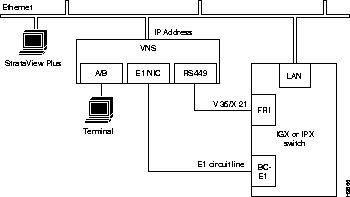
Normally the VNS is connected from its 10Base-T connector (see Figure 6-1) to an Ethernet Hub. (The 10Base-T ethernet hub is not supplied by Cisco.) The node's LAN port and the SV+ Workstation are also connected to this same ethernet segment.
You may have to modify some of the VNS's UNIX operating system (i.e., Solaris 2.4) files for your local LAN environment. To do this, you will need to use a text editor such as vi to modify files and a few simple Sun operating system (SunOS) commands.
vi is a UNIX-based screen editor which can be used to make some minor modifications to the UNIX-based files. You can find out more about vi, by typing man vi at the VNS's UNIX prompt and pressing Enter. In vi there is a command mode and an editing (i.e., insertion) mode. Most commands are entered from the command mode; while the file is actually modified in the editing mode. You quit the editing mode with ESC. Since only minor changes need to be made to VNS UNIX files, you should only need to know a few commands:
When you are logged in to the VNS, you can find out the use and syntax of operating system commands with the man page command; for instance, enter man login to find out about the login command.
A quick procedure for editing any of the files:
Step 1 cd to where the file is located.
Step 2 vi filename.
Step 3 Position cursor where you want to add or change text (use the arrow keys or h, j, k, l).
Step 4 Enter o to add a new line, i to edit a line, or R to enter overwrite mode.
Step 5 Enter your text.
Step 6 Hit ESC when you are done adding text. You are now back in the command mode.
Step 7 Enter ZZ to save the file. (You can use more filename to check that file has been modified).
After checking with your system administrator, set the IP address, hostname, and other parameters necessary for operating the VNS in your local area network environment, as follows:
Step 1 Connect a terminal to the VNS.
Step 2 Log in to VNS as superuser.
Step 3 Use vi to screen edit the file /etc/hosts and add the IP address for VNS and the IP address for the SV+ Workstation.
For direct Ethernet connection where, for example, you have an SV+ Workstation with a hostname of nms and an IP address of 200.1.2.3 and a VNS with a hostname of ins1 and an IP address of 200.1.2.4, you would add the two lines, shown in bold type, to the hosts file:
Contents of /etc/hosts
#
127.0.0.1	localhost
#
200.1.2.4	ins1	loghost	# INS1 (VNS 1 local Ethernet port)
200.1.2.3 nms # SV+ Workstation
#192..x.x.x	fr-ins1	 frhost	# INS1 (Frame-Relay)
# End of hosts


Note that the frhost (frame-relay host) IP address is used for remote SV+ Workstation
connectivity and can be commented out by adding a # sign to beginning of line. This
feature is not used with the VNS.
Step 4 If required for your local network, use vi to screen edit the file /etc/networks, which will appear similar to the following:
Contents of /etc/networks file:
#
# The loopback network is used only for intra-machine communication
#
loopback	127
#
# Internet networks
#
arpanet	10	arpa	# Historical
nms-net	200.1.2		# SV+ network
# End of networks

For our example, the line in bold text, nms-net . . ., is added to the networks
file.
Step 5 If required for your local network, use vi to screen edit the file /etc/netmasks to add the appropriate subnet mask for your LAN segment.
Step 6 If required for your local network, use vi to screen edit the file /etc/hostname.le0 to name the VNS's ethernet port.
Step 7 If required for your local network, use vi to screen edit the file /etc/nodename to name the VNS node, and verify that this name is the same name as /etc/hostname.le0.
Step 8 Use the date SunOS command to set the local date and time.
Step 9 Set the VNS's local timezone by editing /ect/TIMEZONE file. Table 6-1 lists the supported time zones. Open the file (with vi) and look for the line:
Change this line to the required TimeZone;
for example:
Save the /etc/TIMEZONE file .
Step 10 Execute the reboot command to restart the VNS.
Australia/ | Brazil/ | CET | CST6CDT | Canada/ |
Chile/ | Cuba | EET | EST | EST5EDT |
Egypt | Erie | Etc/ | Factory | GB |
GB-Eire | GMT | GMT+0 | GMT+1 | GMT+10 |
GMT+11 | GMT+12 | GMT+13 | GMT+2 | GMT+3 |
GMT+4 | GMT+5 | GMT+6 | GMT+7 | GMT+8 |
GMT+9 | GMT-0 | GMT-1 | GMT-10 | GMT-11 |
GMT-12 | GMT-2 | GMT-3 | GMT-4 | GMT-5 |
GMT-6 | GMT-7 | GMT-8 | GMT-9 | Greenwich |
HST | Hongkong | Iceland | Iran | Israel |
Jamaica | Japan | Kwajalein | Libya | MET |
MST | MST7&MDT | Mexico/ | Mideast | NZ |
NZ-CHAT | Navajo | PRC | PST8PDT | Poland |
ROC | ROK | Singapore | Turkey | UCT |
US/ | UTC | Universal | W-SU | WET |
Zulu | posixrules |
|
|
|
| ||||
| ||||
ACT | Broken_Hill | LHI | NSW | North |
Queensland | South | Tasmania | Victoria | West |
Yancowinna |
|
|
|
|
| ||||
Acre | DeNoronha | East | West |
|
| ||||
Atlantic | Central | East-Saskatchewan | Eastern | Mountain |
Newfoundland | Pacific | Yukon |
|
|
| ||||
Continental | EasterIsland |
|
|
|
| ||||
GMT | GMT+0 | GMT+10 | GMT+11 | GMT+12 |
GMT+2 | GMT+3 | GMT+4 | GMT+5 | GMT+6 |
GMT+7 | GMT+8 | GMT+9 | GMT-0 | GMT-1 |
GMT-10 | GMT-11 | GMT-12 | GMT-13 | GMT-2 |
GMT-3 | GMT-4 | GMT-5 | GMT-6 | GMT-7 |
GMT-8 | GMT-9 |
|
|
|
| ||||
BajaNorte | BajaSur | General |
|
|
| ||||
Riyadh87 | Riyadh88 | Riyadh89 |
|
|
| ||||
Alaska | Aleutian | Arizona | Central | East-Indiana |
Eastern | Hawaii | Michigan | Mountain | Pacific |
Pacific-New | Samoa |
|
|
|
Where the VNS and the StrataView Plus Workstation are not on the same Ethernet, they must communicate over a frame-relay connection. In this case, the SV+ Workstation and the VNS are connected to separate Ethernet segments, as shown in Figure 6-7.
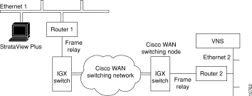
In the situation shown in Figure 6-7, the messages from the VNS to the SV+ (i.e., SNMP Traps) are routed over Ethernet 2 to Router 2 to the Cisco WAN switching network to Router 1 to Ethernet 1 to the SV+ Workstation. The only configuration that needs to be done is to provide the route from the VNS to the SV+ Workstation on the IP network. Consult your network administrator for help in setting up this route over the routers.
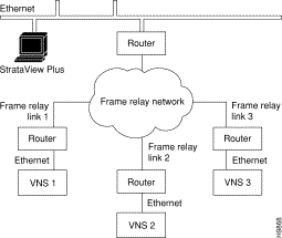
When there are multiple VNSs in the WAN switching network, a separate ethernet connection will have to be made between each VNS and the SV+ Workstation as shown in Figure 6-8. Your network administrator should assist you in setting up these connections over the additional routers.
When configuring redundancy, do not switch on the redundant VNS until the active unit is fully configured. You connect the redundant VNS, or second VNS in a redundant pair, in exactly the same way as you did with the first VNS. As shown in Figure 6-9, the second VNS uses identical physical interfaces:
The Frame Relay Card and E1 NICs physical connections will be to different physical ports on the IGX/IPX switch. The connections can be made to two ports on the same card, however.
The second VNS will also have to have its local LAN environment set up, and it will use a different IP address and host name than the first VNS.
When adding Voice Network Switching (VNS) to a Cisco WAN switching network, the node connected to the VNS will require some high-level adjustments to its operating parameters. These parameters are adjusted with:
Table 6-2 lists these commands and the parameters that can have an effect on the operation of a VNS network. During an initial installation of a VNS, these parameters have to be changed as indicated in the table.
 | Caution The cnfnodeparm and cnfcmparm are superuser-level commands and should be used carefully. And, although the cnftrk command is not superuser-level command, it should also be used carefully. Note that these parameter changes can adversely affect your network's operation. They should be adjusted only after your network has been carefully modeled. |
Each of the nodes (i.e., Cisco wide-area switches) in the network need to have their SNMP community names set up before Voice Network Switching will work. You should ensure that the Cisco wide-area switch and network have seen set up for proper IP connectivity. If necessary, refer to the Release 8.4 Cisco WAN Switching Command Reference or Cisco WAN Switching SuperUser Command Reference and use the following commands:
The VNS must be able to communicate with each node in the network. If there is not an Ethernet connection to each node, the VNS can communicate with the nodes through IP Relay. This involves setting up the Network IP addresses (cnfnwip), creating a Network IP (NWIP) subnet, and adding the gateway to that subnet with the route add net command on the VNS. (The route add net command can be stored in a file at /etc/rc3.d that executes at system startup time.)
For instance in Figure 6-10, IGX switch 1 is connected to the same Ethernet segment as VNS 1. IGX switch 1 has a LAN IP address of 200.1.2.5. The other three IGX switches (IGX switch 2, 3, and 4) will communicate with VNS 1 using IP Relay. This IP Relay network will have become a subnet with address 200.200.200.0. Traffic from VNS 1 to IGX switch 2, 3, or 4 has to be directed out the Network IP (NWIP) subnet (200.200.200.0) through IGX switch 1. In effect IGX switch 1 serves as a gateway to the NWIP subnet.
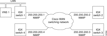
To configure this sample NWIP subnet, you would follow these steps:
Step 1 The Network IPs (NWIP) for each of the four nodes will have to be configured with each node's cnnwip command. (They are all be put on the same subnet with the subnet mask argument, 255.255.255.0.)
Step 2 Next you would log into the VNS and create a file containing the UNIX-level route add net command. The command is:
route add net 200.200.200.0 200.1.2.5 1
Where 200.200.200.0 is the network address of the NWIP subnet, and 200.1.2.5 is the LAN address of IGX switch 1. Note that there is a space between the two IP addresses and a space between the second IP address and the 1. The 1 after the second IP address is a hop metric and must be non-zero if the destination is not directly connected to the VNS's Ethernet segment.
This file with the route add net command should saved in /etc/rc3.d and could be named S70route, as in this example file:
/etc/rc3.d more s70route

#Sample S70route file
#route add default xxx.xxx.xxx.xxx #if applicable, add the address of the default
router
route add net 200.200.200.0 200.1.2.5 1
#
# End
This file executes at system startup.
Often Voice Network Switching is added to a Cisco WAN switching network which has previously been configured for voice connections. When migrating voice connections to a VNS network, you should consider the following commands which may have to be adjusted:
cnfchgn (Configure Channel Gain)
cnfchadv (Configure Channel Adaptive Voice)
cnfecparm (Configure Integrated Echo Cancellor Parameters)
The cnfchgn and cnfchadv commands are described in the Cisco WAN Switching Command Reference in the Chapter on Voice Connections. The cnfecparm command is a superuser-level command and is described in the Cisco WAN Switching SuperUser Command Reference. Note that the cnfecparm command is used to set the Voice Template parameter, which selects either normal level (USA) or high-level (UK) voice.
The rdate command sets the VNS time from a specified remote host (that is, another VNS) and takes the form:
rdate <hostname or ipaddress>
Where hostname or ipaddress is the VNS from which you want to get the time to synchronize another VNS.
For instance, if you had 4 VNSs in your network (vns1, vns2, vns3, and vns4) and you want vns1 to be the master for the time for all the VNS systems. You could create a script named vns_set_time on each of the other VNSs (vns2, vns3, and vns4.) The script could look like:
#!/etc/csh
/usr/bin/rdate vns1
Make the scripts executable; as root user, issue the command:
chmod 700 vns_set_time
This assumes that the /etc/host file is updated with the IP address to host names for all the VNSs in the system. You run this file as a cron job, a UNIX system feature which uses the cron daemon to execute processes at specified times.
You create the cron job by editing the root crontab file on vns2, vns3, and vns4. Use crontab -e root and add the following line to the file:
30 1 * * * /usr/local/bin/vns_set_time > /dev/null 2>&1
This schedules the script vns_set_time to run at 1:30 am. /dev/null 2>&1directs the error messages to a null file.
A crontab file consists of lines of six fields each. The fields are separated by spaces or tabs. The first five are integer patterns that specify the following:
The example runs vns_set_time everyday at 1:30 am. The vns_set_time file has to be run as a cron job on every VNS that needs to synchronize its date and time from vns1.
After you have connected and configured the VNS(s), you should log in (or have someone log in) to the SV+ Workstation and Ping the VNS to ensure that they are communicating. You should also be able to ping all the remote nodes.
The rest of the configuration of a VNS network is done with the VNS Configuration Interface, described in Chapter 7. Chapter 8, VNS Network Operation, describes using the VNS Configuration Interface to provision the VNS network.
After you determine that StrataView Plus and the VNS are communicating (as a result of Ping), you need to install a network map icon, which represents either the VNS or its redundant VNS, on the topology maps of the SV+ Workstation. A VNS icon is added, modified, or deleted only through HP OpenView. This icon shows only the existence of the VNS; StrataView Plus does not manage the VNS object. StrataView Plus does receive SNMP Traps from the VNS, however, and will display the status of the VNS with different colors:
Green | Normal |
Yellow | Minor alarm |
Red | Major alarm |
Brown | VNS unreachable |
The VNS icon is only visible on the SV+ Workstation where it was added.
To add a VNS icon, which requires access to the HP OpenView network topology main menu on the SV+ Workstation, follow these steps:
Step 1 At the SV+ Workstation open an HP OpenView window (at the UNIX prompt, change to the OV directory, then enter ovw).
Step 2 Double-click your network icon to open a Network Topology window and map, shown in Figure 6-11.
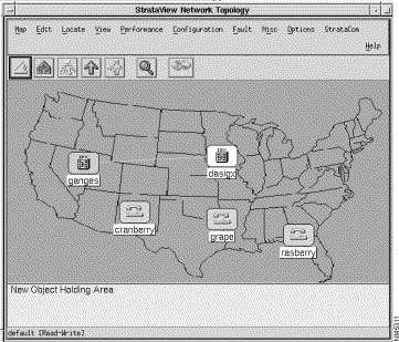
Step 3 Select the Edit - Add Object... menu.
The Add Object: Palette window appears.
Step 4 Click on the StrataView icon on the Add Object: Palette to open the Symbol Subclasses window where you will find the VNS icon as shown in Figure 6-12.

Step 5 Using the middle mouse button, drag and drop the VNS symbol from the Palette to the map as shown in Figure 6-13. The Add Object window appears.
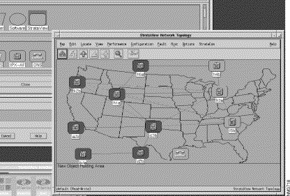
Step 6 In the Add Object window, shown in Figure 6-14, you name the VNS object and call up another window to set its object attributes by identifying the Cisco wide-area switch to which it is attached. To name the VNS object:
Label: box and enter the host name of the VNS. (This name will be displayed with the symbol on the map if you select Yes at the Display Label field.)
Display Label: radio buttons:
Behavior: radio buttons:
Explode causes the submap to display when the symbol is double-clicked.Execute permits the symbol to execute an application which performs an action on a set of objects when it is double-clicked. 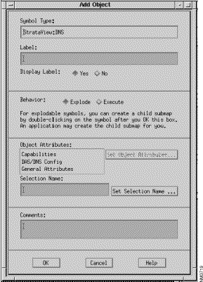
Step 7 Next Select DAS/DNS Config in the Object Attributes: box. This will activate the Set Object Attributes... button.
Step 8 Click the Set Object Attributes... to present the Add Object - Set Attributes window, shown in Figure 6-15, for DAS/DNS Config. The host name of the VNS that you entered in the previous window will appear in the VNS Node Name box.
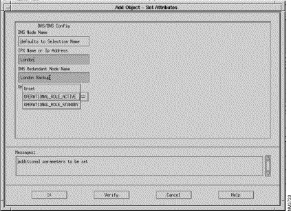
Step 9 In the next three boxes, you enter information about the Cisco wide-area switch to which the VNS is attached:
IPX Name or IP Address box, enter the node name of the Cisco wide-area switch (IGX/IPX switch) to which the VNS is attached.
VNS Redundant Node Name box, enter the name number of this VNS's peer VNS.
Operational Role box, enter the active or standby role of this VNS.
Step 10 If you have entered your information correctly, press the Verify button. The OK button will activate.
Step 11 Press the OK button, you will return to the Add Object window. Press the OK button on the Add Object window and you will return to the HP OpenView network topology map.
You must use the StrataCom pull-down menu to remove an INS icon (that is, VNS) from a network topology map. Using any of the other HP OpenView tools, such as Edit--Delete, will cause an error.
To remove the INS icon from you network topology map, follow these steps:
Step 1 With your network topology map displayed, select the VNS icon on the map.
Step 2 Pull down the StrataCom menu from the top menu bar.
Step 3 Select Remove DNS Station from the StrataCom pull down menu.
With this release, user-access verification has been added to the VNS Configuration Interface (i.e., vnscli). In other words, the use of the VNS Command Line Interface is password controlled. The password control has been added through a UNIX-Level vns_passwd file.
Adding a user with specific privileges takes two steps:
1. Add a UNIX User
2. Add the VNS User
Adding UNIX users and controlling the vns_passwd file should typically be done by your system administrator.
The system administrator generally adds UNIX users with the Solaris admintool. With its graphical user interface, the admintool simplifies adding users to UNIX operating systems, a task which previously had to be done with the adduser command and by editing the /etc/group file.
To add a UNIX user, the system administrator would follow these steps:
Step 1 From the StrataView Plus Workstation, rlogin or telnet to the VNS.
Step 2 Log in to the VNS as root.
Step 3 At the root prompt, type admintool. The Administration Tool opening screen will appear.
Step 4 Click on the User Account Manager button. The User Account Manager window appears.
Step 5 Press the Edit button and select the Add User option. This will bring up the User Information window.
Step 6 Fill in the username, userid, and the various options. There is a Help button on the menu that provides information about the various options.
Step 7 Press the Add button. The UNIX user now has been added to the VNS.
VNS users can be added only after they are UNIX users. The VNS user is added by editing the file /etc/vns_passwd and adding an entry for the VNS user. The entry in the vns_passwd file has the following format:
VnsUserName:Permissions
VnsUserName is the username of the VNS user and must be the same as the one used for the UNIX user which was just added. Permission is the string which specifies the various VNS CLI operations which the user will be permitted to perform. The valid permission options are each specified by a single letter, that is `a' or `d' or `m' or `b' or `g' and provide the following permissions:
The two fields must be separated by ':' , the field separator.
A sample factory-default VNS password (vns_passwd) file is shown below:
vns_passwd File
#################################################################
#		This is the passwd file which determines user access to the VNS
#		database which should exist in /etc.
#
#		The sample format given below has to be adhered to for adding
#		new users.
#
#		format	:	user_login_id:permissions
#
#		"permissions" can be a string of any of the letters `a', `d', `m',
#		`b', `g', `v' which stand for add, delete, modify, browse, debug and validate
#		respectively. These can be specified in any order.
#
#		The user will be allowed to perform only the operations specified
#		by the permission string, on the VNS database using the vnscli.
#
#		The entry for root has been added by default. This line may be
#		yanked and the required number of users and their permissions
#		may be added. A user not listed in this file is not allowed to
#		run vnscli. vnscli also does not run if this file is not present.
#
#		A `#' in the first column of a line turns the line into a comment.
#		Users may be deleted by commenting out the corresponding line also.
#
##################################################################
root:amdbgv:
This vns_passwd file shows the root as having all available vnscli privileges (amdbg) as described in the dns_passwd file's comments. To add other users and privilege levels, you edit the file /etc/vns_passwd and add users as shown below:
########################
root:amdbg:
njones:admb:
bsmith:b:
pnirmel:admbv:
Each user is added as a line in the file with the associated privilege levels. In the example above, njones has add, delete, modify, and browse privileges and nsmith has browse (read only) privileges. Save the vns_passwd file after you have added additional VNS users. If the file /etc/vns_passwd does not exist, the VNS Command Line Interface (vnscli) will only operate in the browse mode.
For security reasons, the Solaris operating system on the VNS prevents root users from gaining access via telnet. Until this feature is disabled, remote management of the VNS is significantly impaired.
To allow a root user to log in remotely, you have to edit the file /etc/default/login to comment out (add a # symbol in front of the line) the line:
CONSOLE=/dev/console
The following is an example of the /etc/default/login file. The text in bold-face type points out the lines relevant to CONSOLE=/dev/console:
tstvns8# more login
#ident  "@(#)login.dfl  1.7     93/08/20 SMI"   /* SVr4.0 1.1.1.1       */

# Set the TZ environment variable of the shell.
#
#TIMEZONE=EST5EDT

# Set the HZ environment variable of the shell.
#
HZ=100

# ULIMIT sets the file size limit for the login.  Units are disk blocks.
# The default of zero means no limit.
#
#ULIMIT=0

# If CONSOLE is set, root can only login on that device.
# Comment this line out to allow remote login by root.
#
#CONSOLE=/dev/console
#
# PASSREQ determines if login requires a password.
#
PASSREQ=YES
#
#
# ALTSHELL determines if the SHELL environment variable should be set
#
ALTSHELL=YES

# PATH sets the initial shell PATH variable
#
#PATH=/usr/bin:

# SUPATH sets the initial shell PATH variable for root
#
#SUPATH=/usr/sbin:/usr/bin

# TIMEOUT sets the number of seconds (between 0 and 900) to wait before
# abandoning a login session.
#
#TIMEOUT=300

# UMASK sets the initial shell file creation mode mask.  See umask(1).
#
#UMASK=022

# SYSLOG determines whether the syslog(3) LOG_AUTH facility should be used
# to log all root logins at level LOG_NOTICE and multiple failed login
# attempts at LOG_CRIT.
#
SYSLOG=YES
tstvns8#
|
|