|
|

Table Of Contents
Module and Service Descriptions
PXM1 Illustration and LED Description
PXM1 User Interface Back Cards
Making External Clock Connections
Module Requirements with Bulk Distribution and Redundancy
Installation Requirements for the MGX-SRM-3T3/C
SRM Illustration and LED Indicators
Rules for FRSM Slot Installation
Redundancy for Frame Service Modules
Types of Frame Service Modules
Circuit Emulation Service Modules
Module and Service Descriptions
This chapter includes detailed descriptions of the modules, cards and services available with the MGX8250.
•
ATM UNI Service Module (AUSM)
•
Processor Switching Module
The PXM1 card set consists of the PXM1 front card, the PXM1 User Interface back card (PXM1-UI or PXM-UI-S3), and various uplink back cards that can serve as either a trunk or a UNI.
For physical details of PXM1 cards, see "System Specifications."
Caution
Caution
Note
PXM1 Features
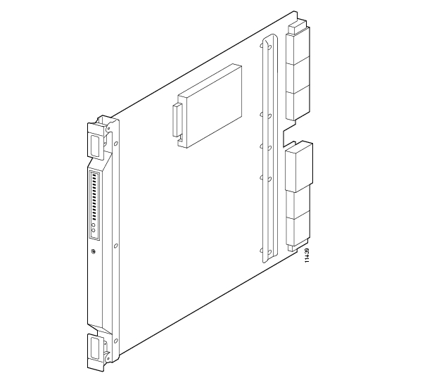
The PXM1 (see Figure2-1) is a combination ATM switching fabric, data processing, and ATM interface card. This module combines a 1.2 Gbps shared-memory switching fabric with integrated trunking at speeds up to OC-12. The switching fabric provides 1.2 Gbps of non-blocking switching capacity, while the processor provides the control plane that delivers IP+ATM networking software, diagnostics, and performance monitoring.
The PXM provides integrated switching, processing, and broadband interfaces to provide the following high-performance switching and trunking features:
•
•
•
•
Note
•
•
•
•
•
•
•
•
PXM1 Illustration and LED Description
PXM1 provides connectors for external audio and visual alarms. The interface can either be always open or always closed. Major and minor alarms are controlled separately. An alarm cutoff button is accessible from the front. A history LED is set when the alarm cutoff button is pressed. The history LED can be cleared by pressing the history clear button on the faceplate.
The PXM1 provides the following indicators:
•
•
•
•
•
•
•
•
•
•
Figure 2-1 PXM1 Front Card
PXM1 User Interface Back Cards
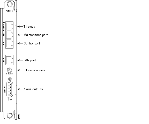
The PXM1 User Interface (PXM1-UI) back card provides ports for communication and control. This card is also used to connect the system to an external clocking source. Install this card in the upper half of the back of the PXM1. See the "User Interface Access Ports" section for more information on the PXM1 back card ports.
There are two options for the PXM1 back card.
1. PXM1-UI ( standard)
The PXM1-UI back card shown in Figure2-2 provides
•
•
•
•
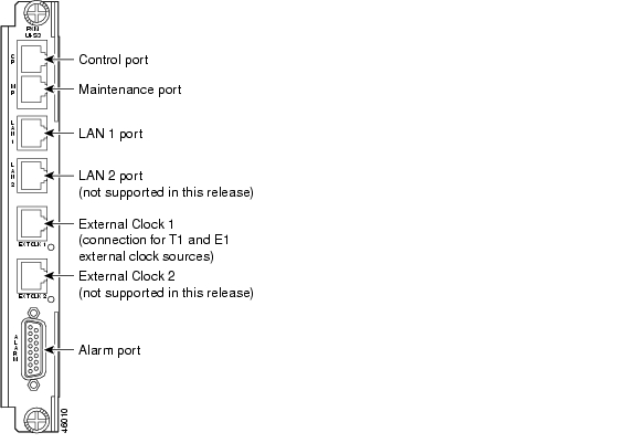
2. PXM-UI-S3 (optional)
The PXM-UI-S3 back card shown in Figure2-3 provides Stratum-3 clocking:
•
•
•
Note
Making External Clock Connections
If external equipment or a local digital central office is to provide synchronization, the external clock source is connected to the PXM1-UI or PXM-UI-S3 back card.
Stratum-4 Clocking
External clocking sources are connected to the PXM1-UI back card (see Figure2-2).
•
•
Stratum-3 Clocking
External clocking sources are connected to the PXM-UI-S3 back card (see Figure2-3).
For T1 and E1 Stratum-3 external clock input, connect the source to the RJ-45/48 connector labeled "CLK1."
Note
See "Configuring the MGX 8250 Shelf" for information on configuring an external clocking source.
PXM1 Back Card Illustrations
This section contains illustrations of the following PXM1 cards:
•
•
•
•
•
•
•
PXM1 User Interface Back Cards
See the "PXM1 User Interface Back Cards" section for descriptions of the features available with the PXM1 User Interface (PXM1-UI) back cards.
Figure 2-2 PXM1-UI Back Card
Figure 2-3 User Interface Back Card (PXM-UI-S3)—Stratum-3 Clocking
Alarm Output Connection
Dry contact relay closures are available for forwarding MGX 8250 alarms to an alarm system. Separate visual and audible alarm outputs are available for major and minor alarm outputs. The MGX 8250 alarm outputs are available on a DB-15 connector on the PXM-UI-S3 back card faceplate. See AppendixB, "Cabling Summary," for the pinouts on this connector. Use the switchboard cable for running these connections.
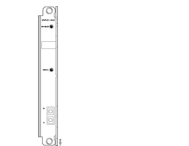
SMFLR-1-622 Back Card
An illustration of the long-reach OC-12 card appears in Figure2-4. For specifications on this card, see "System Specifications."
Note
Figure 2-4 OC-12 Long-Reach Back Card (SMFLR-1-622/B)
SMFIR-1-622 Back Card
The intermediate-reach OC-12 back card appears in Figure2-5. For specifications on this card, see "System Specifications."
Note
Figure 2-5 OC-12 Intermediate-Reach Back Card (SMFIR-1-622)
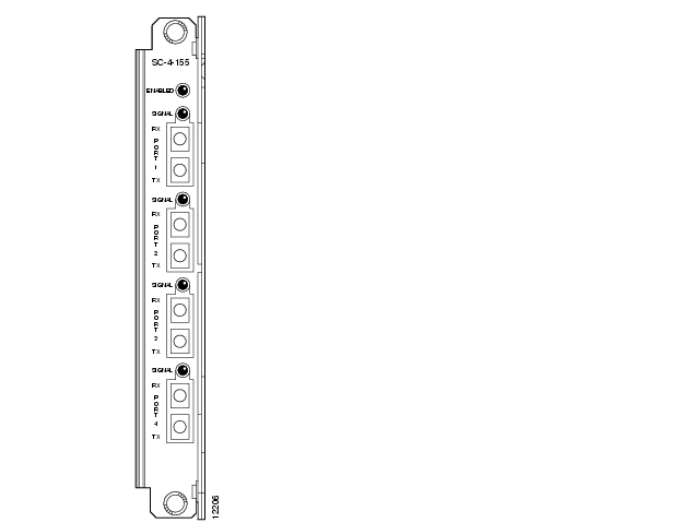
SMF-155 Back Card
The SMF-155 back card provides a physical single-mode fiber optic SONET OC-3 interface that conforms to ANSI T1.105 and GR-253-CORE standards. This interface uses SC connectors. Redundant configurations are supported through Y-cables. For specifications on this card, see "System Specifications."
Note
Figure 2-6 OC-3 Four-Port Back Card (SMF-155/B)
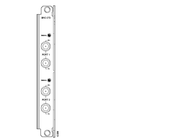
BNC-2T3 Back Card
The BNC-2T3 back card appears in Figure2-7, for card specifications, see "System Specifications."
Figure 2-7 Two-port T3 Back Card (BNC-2T3)
BNC-2E3 Back Card
Two versions of the BNC-2E3 card are available; the BNC-2E3 card and the BNC-2E3A card. The BNC-2E3A card applies to Australia only. The BNC-2E3 applies to all other sites that require E3 lines on the PXM1 uplink card. An illustration of the two-port E3 back card appears in Figure2-8. For specifications on this card, see "System Specifications."
Figure 2-8 Two-port E3 Back Card (BNC-2E3)
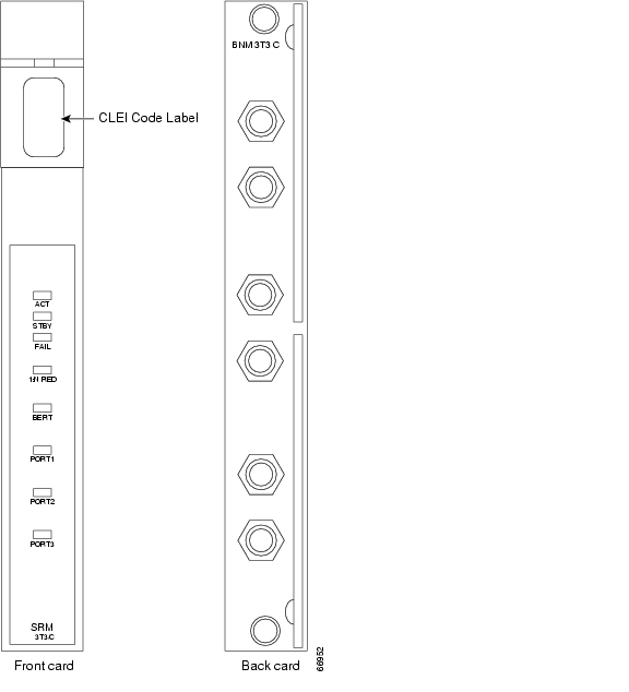
Service Resource Module
A service resource module (SRM) provides three main functions for the service modules:
•
See Figure2-9 for an illustration of the MGX-SRM-3T3/C front card and the MGX-BNC-3T3-M back card.
Bit Error Rate Testing
After a service module line or port is put into loopback mode, the SRM can generate a test pattern over the looped line or port, read the received looped data, and report on the error rate. This operation can be performed on a complete T1 or E1 line, on a fractional T1 or E1 line, on a SD0 bundle (NxDS0), or on a single DS0 channel. The SRM can support Bit Error Rate Testing (BERT) only one line or channel at a time. BERT is capable of generating a variety of test patterns, including all ones, all zeros, alternate one zero, double alternate one zero, 223-1, 220-1, 215-1, 211-1, 29-1, 1 in 8, 1 in 24, DDS1, DDS2, DDS3, DDS4, and DDS5.
1:N Service Module Redundancy
Service module redundancy provides 1:N redundancy for multiple groups of service modules (a group consists of N active and one standby service module). The redundant service module in a group must be a superset (with respect to functionality) of the cards. Upon the detection of a failure in any of the service modules, the packets destined for the failed service module are carried over the cellbus to the SRM in its chassis. The SRM receives the packets and switches them to the backup service module via the cellbus.
Bulk Distribution Mode
Each of the T3 ports can be used to support up to 28-multiplexed T1 lines, which are distributed to T1 service module ports in the switch. Called bulk distribution, this feature is performed when the SRM is in bulk mode. The purpose of this feature is to allow large numbers of T1 lines to be supported over three T3 lines rather than over individual T1 lines.
Out of the maximum possible 84-T1 channels (3 times 28), up to 80 channels per shelf can be active at any time. Any T1 channel in a T3 line can be distributed to any eight port on a service module in any slots of the shelf without restriction. Each MGX 8250 shelf can support up to 80 T1/E1s, and the whole chassis supports up to 160 T1s. As an option, the SRMs can use back cards and native T1/E1 interfaces to bring the total to 192 DS1s; 160 DS1s using twenty 8-port cards and the SRMs, and 32 DS1s using four 8-port cards with T1/E1 back cards (for the MGX 8250).
The SRM-3T3 can also be operated in nonbulk mode on a port-by-port basis. For a port configured in nonbulk mode, bulk distribution is disabled and the SRM provides BERT and 1:N redundancy functions only.
Linking the MGX-SRM-3T3/C to a destination card causes the switch to take CPE traffic through the MGX-SRM-3T3/C rather than the T1 card's line module. Linkage is a card-level condition. If you link just one T1 channel on a service module to the MGX-SRM-3T3/C, the back card on the service module becomes inoperative, so you must link all other T1 ports on that service module to the MGX-SRM-3T3/C if you want them to operate.
Module Requirements with Bulk Distribution and Redundancy
The use of bulk distribution affects the requirements for SRM and service module back cards:
•
•
•
Installation Requirements for the MGX-SRM-3T3/C
The following card-level characteristics apply to any SRM installation:
•
•
•
•
•
•
•
•
•
•
SRM Illustration and LED Indicators
describe the SRM-3T3 LED faceplate indicators.
Figure 2-9 MGX-SRM-3T3/C Card Set
ATM UNI Service Module (AUSM)
The main function of the AUSM cards is to provide an ATM UNI/NNI interface at T1 or E1 rates so that ATM UNI user devices can transmit and receive traffic. This section contains the following information:
AUSM Features
The MGX-AUSM-8T1/B and MGX-AUSM-8E1/B (AUSM) are multipurpose front cards that use an eight-port T1 or E1 back card to provide native ATM UNI interfaces.
A single AUSM/B card can provide hot standby redundancy for all active AUSM/B cards of the same type (1:N redundancy).
AUSM/B modules are supported by standards-based management tools, including Simple Network Management Protocol (SNMP), Trivial File Transfer Protocol (TFTP) for configuration and statistics collection, and a command-line interface. Cisco's WAN Manager service management tool provides full graphical user interface support for connection and equipment management.
Quality of Service Management
Consistent with the Cisco intelligent quality of service (QoS) management features, AUSM/B cards support per-VC queuing on ingress and multiple class of service queues on egress. AUSM/B cards fully support continuous bit rate (CBR), variable bit rate (VBR), unspecified bit rate (UBR), and available bit rate (ABR) service classes.
Inverse Multiplexing
AUSM/B cards also support ATM Forum-compliant inverse multiplexing for ATM (IMA). This capability enables multiple T1 or E1 lines to be grouped into a single high-speed ATM port. This NxT1 and NxE1 capability fills the gap between T1/E1 and T3/E3, providing bandwidth up to 12 Mbps (NxT1) or 16 Mbps (NxE1), without requiring a T3/E3 circuit.
Inverse Multiplexing for ATM
•
•
•
•
•
•
Physical Layer Features
Table2-3 shows the physical layer features for all cards, T1 cards, and E1 cards.
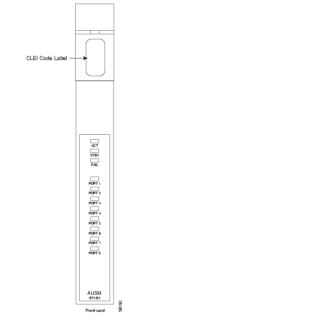
AUSM Front Card
The AUSM/B front card oversees all major functions of the ATM interface. It contains firmware for both the T1 and the E1 line interfaces and downloads from the PXM1 the appropriate code when it recognizes the back card type. An illustration of an eight-port AUSM/B front card appears in Figure2-10. For specifications on this card, see "System Specifications."
Figure 2-10 AUSM/B-8T1 or AUSM/B-8E1 Front Card
Table2-4 contains a list of eight-port LED indicators.
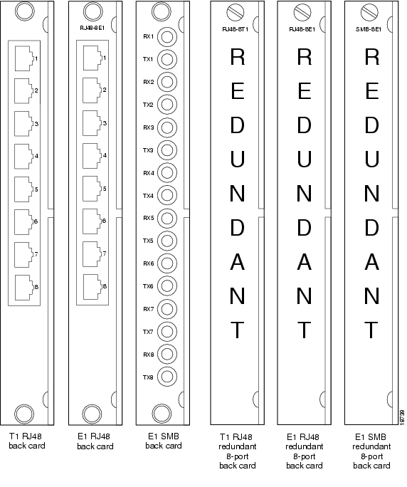
Back Cards for the AUSM/B
The MGX-AUSM-8T1/B and MGX-AUSM-8E1/B use the generic eight-port T1 or E1 line modules that operate with the eight-port service modules (see Figure2-11).
•
•
•
1:N Redundancy support for the AUSM requires the special versions of the RJ-45 back cards (see Figure2-11). These back cards are
•
•
•
Note
Figure 2-11 RJ-48 and SMB Back Cards for the MGX-AUSM-8T1E1/B
Frame Relay Service Modules
The primary function of the Frame Relay Service Modules (FRSM) is to convert between the Frame Relay formatted data and ATM/AAL5 cell-formatted data. For an individual connection, you can configure network interworking (NIW), service interworking (SIW), ATM-to-Frame Relay UNI (FUNI), or frame forwarding. An FRSM converts the header format and translates the address for
•
•
•
See the "Configuring Frame Relay Service" section on page6-29 for instructions to configure the FRSMs.
This section contains the following information:
•
•
•
•
•
–
Features Common to All FRSMs
This section describes features common to all FRSMs. For features specific to the individual module types, see Types of Frame Service Modules. For information to configure the FRSMs, see Chapter6, "Card and Service Configuration".
Data-Link Layer Features
•
•
•
•
•
Frame Relay Features
•
•
•
•
•
•
•
•
•
Note
ATM FUNI features
The MGX 8250 FRSMs support the following ATM FUNI features.
•
•
•
•
•
•
•
•
Note
Frame Forwarding features
The MGX 8250 FRSMs support the following frame forwarding features.
•
•
•
•
•
•
Note
Rules for FRSM Slot Installation
The rules for slot installation are as follows:
•
•
•
Note
Redundancy for Frame Service Modules
FRSMs can have either hot standby, 1:1 redundancy, or 1:N redundancy.
•
•
•
•
Note
Hot Standby
For hot standby, place the card sets in slots on the same card shelf and connect using an appropriate Y-cable to connect each hot standby pair. To view the hot standby status of the system, enter the dsphotstandby command.
1:1 Redundancy
For 1:1 redundancy, place the card sets in adjacent slots and connect a Y-cable for each pair of active and standby ports. On the CLI, configure the card for redundancy by entering the addred command. For instructions on how to use the CiscoView application to configure redundancy, refer to the CiscoView documentation.
1:N Redundancy
1:N redundancy for the eight-port FRSMs requires an MGX-SRM-3T3/C. With 1:N redundancy, a group of service modules includes one standby module. For installation requirements, see " "Service Resource Module" section ". For configuration requirements, see Chapter6, "Card and Service Configuration" in the "Service Resource Module" section.
Connection Types on the FRSM
The following sections describe NIW, SIW, FUNI, and Frame forwarding. Topics include translation and congestion management.
•
•
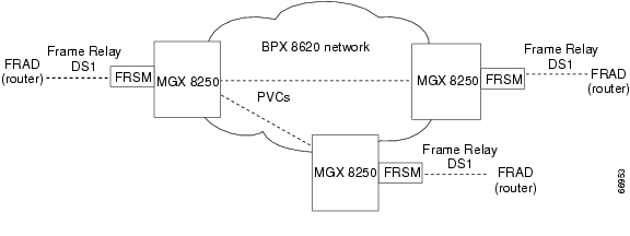
Frame Relay-to-ATM Network Interworking
Frame Relay-to-ATM network interworking (NIW) supports a permanent virtual connection (PVC) between two Frame Relay users over a Cisco network or a multi-vendor network. The traffic crosses the network as ATM cells. To specify NIW for a connection, add the connection with a channel type of "network interworking." For an illustration of a BPX 8620 network with NIW connections, see Figure2-12.
Figure 2-12 BPX 8620 Network with NIW Connections
Congestion Indication for NIW Connections
In addition to frame-to-cell and DLCI to VPI/VCI conversion, the network interworking feature maps cell loss priority (CLP) and congestion information from Frame Relay to ATM formats. The CLP and congestion indicators can be modified for individual connections entering the cnfchanmap command .
Frame Relay-to-ATM Direction
Each Frame Relay/ATM network interworking connection can be configured as one of the following DE to CLP mapping schemes:
•
•
•
ATM-to-Frame Relay Direction
Each Frame Relay/ATM network interworking connection can be configured as one of the following CLP to DE mapping schemes:
•
•
Congestion Indication
Congestion on the Frame Relay/ATM network interworking connection is flagged by the EFCI bit. The setting of this feature is dependent on traffic direction, as described below.
Frame Relay-to-ATM Direction
EFCI is always set to 0.
ATM-to-Frame Relay Direction
If the EFCI field in the last ATM cell of a segmented frame received is set, then FECN of the Frame Relay frame will be set.
PVC Status Management
The management of ATM layer and FR PVC status management can operate independently. The PVC status from the ATM layer is used when determining the status of the FR PVC. However, no direct actions of mapping LMI A bit to OAM AIS is performed.
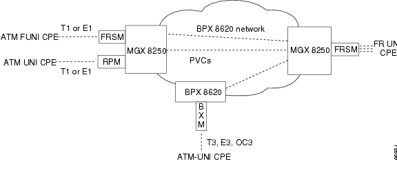
Frame Relay-to-ATM Service Interworking
By specifying "service interworking" as the channel type when adding a Frame Relay PVC to an FRSM, all PVC data is subject to service interworking translation and mapping in both the Frame Relay-to-ATM and ATM-to-Frame Relay directions. Figure2-13 is an illustration of typical SIW connections.
Figure 2-13 BPX 8600 Series Network with SIW Connections
In Figure2-13, an MGX 8250 node on the right has three-Frame Relay SIW connections terminating on an FRSM. Three far end terminations for these connections appear in other parts of Figure2-13.
•
•
•
In addition to frame-to-cell and DLCI-to-VPI/VCI conversion, SIW maps cell loss priority and congestion data between the Frame Relay and ATM formats and is FRF.8-compliant. It provides full support for routed and bridged PDUs, transparent and translation modes, and VP translation.
Cell Loss Priority
In addition to frame-to-cell and DLCI-to-VPI/VCI conversion, the SIW feature maps cell loss priority (CLP) and congestion information from Frame Relay-to-ATM formats and is FRF.8-compliant. It provides full support for routed and bridged PDUs, transparent and translation modes, and VP translation. The CLP and congestion parameters can be modified for individual connections with the cnfchanmap command.
Frame Relay-to-ATM Direction
Each Frame Relay-to-ATM service interworking connection can be configured as one of the following Discard Eligibility (DE) to CLP schemes:
•
•
•
ATM-to-Frame Relay Direction
Each Frame Relay-to-ATM service interworking connection can be configured as one of the following CLP to DE mapping schemes:
•
•
•
Setting up the cell loss priority option is accomplished through the MGX 8250 cnfchanmap (configure channel map) command.
Congestion Indication
Frame Relay-to-ATM Direction
Each Frame Relay-to-ATM service interworking connection can be configured as one of the following Forward Explicit Congestion Notification (FECN) to Explicit-Forward Congestion Indicator (EFCI) schemes:
•
•
•
ATM-to-Frame Relay Direction
Frame Relay-to-ATM service interworking connections use the following EFCI to FECN/BECN mapping schemes:
•
•
•
Command and Response Mapping
Command and Response Mapping is provided in both directions.
Frame Relay-to-ATM Direction
The FRSM maps the C/R bit of the received Frame Relay frame to the CPCS-UU least-significant bit of the AAL5 CPCS PDU.
ATM to Frame Relay Direction
The least-significant bit of the CPCS-UU is mapped to the C/R bit of the Frame Relay frame.
Translation and Transparent Modes
Each service interworking (SIW) connection can exist in either translation or transparent mode. In translation mode, the FRSM translates protocols between the FR NLPID encapsulation (RFC 1490) and the ATM LCC encapsulation (RFC 1483). In transparent mode, the FRSM does not translate. Translation mode support includes address resolution by transforming address resolution protocol (ARP, RFC 826) and inverse ARP (ARP, RFC 1293) between the Frame Relay and ATM formats.
Frame Forwarding
The FRSM card can be configured as "Frame Forwarding" on a port-by-port basis.
Frame forwarding differs from the Frame Relay in the following respects.
•
•
•
•
•
ATM Frame-to-User Network Interface
All FRSMs support the ATM Frame-based User-to-Network Interface (FUNI). When a frame arrives from the FUNI interface, the FRSM removes the 2-byte FUNI header and segments the frame into ATM cells by using AAL5. In the reverse direction, the FRSM assembles ATM cells from the network into a frame by using AAL5, adds a FUNI header to the frame, and sends it to the FUNI port.
Loss Priority Indication
Loss Priority Indication mapping is provided in both directions.
FUNI-to-ATM Direction
The CLP bit on the FUNI header is mapped to the CLP bit of every ATM cell that is generated for the FUNI frame.
ATM-to-FUNI Direction
CLP bit in the FUNI header is always set to 0.
Congestion Indication
Congestion Indication mapping is provided in both directions
FUNI-to-ATM Direction
EFCI is set to 0 for every ATM cell generated by the segmentation process.
ATM-to-FUNI Direction
If the EFCI field in the last ATM cell of a received segmented frame is set to 1, the CN bit in the FUNI header is set to 1. The two reserve bits (the same positions as C/R and BECN in Frame Relay header) are always set to 0.
Types of Frame Service Modules
There are three types of FRSMs:
•
Note
FRSMs for T1 and E1 Lines
The eight-port FRSMs for T1 or E1 lines support channelized or unchannelized service. These cards provide interface support as follows.
•
•
•
•
FRSM for T1 features
The FRSM-8T1 and FRSM-8T1-C each provide eight T1 interfaces for full-duplex communications at up to 1.544 Mbps.
Each T1 line consists of an RJ-48, along with three LED indicators for line status. The FRSM-8T1 supports fractional and unchannelized T1 port selection on a per-T1 basis. The FRSM-8T1-C allows full DS0 and NxDS0 channelization of the T1s, for a maximum of 192 ports per FRSM-8T1-C.
Key features include:
•
•
•
•
•
•
•
•
•
FRSM for E1 features
The FRSM-8E1 and FRSM-8E1-C each provide eight E1 interfaces for full-duplex communications at up to 2.044 Mbps. Each E1 line consists of an RJ-48 and SMB mini-connector, along with three LED indicators for line status.
The FRSM-8E1 supports fractional and unchannelized E1 port selection on a per-E1 basis. The FRSM-8E1-C allows full DS0 and NxDS0 channelization of the E1s, for a maximum of 248 ports per FRSM-8E1-C.
Key Features include:
•
•
•
•
•
•
•
•
•
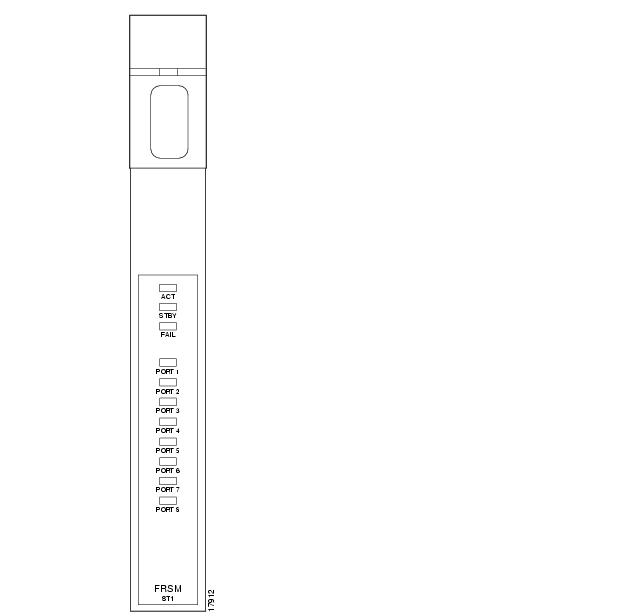
LED Indicators
Table2-5 Card Level LED Indicators for the FRSM T1/E1
ACT
Green
Active
STBY
Yellow
Standby
FAIL
Red
Fail
describe the FRSM T1/E1 LED faceplate indicators.
Table2-6 Line Level LED Indicators for the FRSM T1/E1
PORT
Green
Active and OK
Red
Active and Local Alarm
Yellow
Active and Remote Alarm
Card Illustrations
•
•
–
–
Figure 2-14 MGX-FRSM-8T1
Figure 2-15 RJ-48 and SMB Back Cards for the MGX-FRSM-8T1/E1
FRSMs for T3 and E3 lines
The FRSMs for T3 and E3 lines include
•
•
Features
This section describes the features specific to the T3 and E3 interfaces. See the "Features Common to All FRSMs" section for a description of features that apply to all FRSM modules.
T3 Interfaces
•
•
•
•
•
•
•
•
Note
E3 Interfaces
•
•
•
•
•
•
•
•
Note
Card Combinations
The following card combinations are supported:
•
•
Note
Illustrations
For Illustrations of the Very High Speed FRSM front and back cards, see the following illustrations:
•
•
•
•
FRSM-2T3E3 LED Indicators
Table2-7 Card Level LED Indicators for the FRSM-2T3E3
ACT
Green
Active
STBY
Yellow
Standby
FAIL
Red
Fail
describe the FRSM-2T3E3 LED faceplate indicators.
Table2-8 Line Level LED Indicators for the FRSM-2T3E3
PORT
Green
Active and OK
Red
Active and Local Alarm
Yellow
Active and Remote Alarm
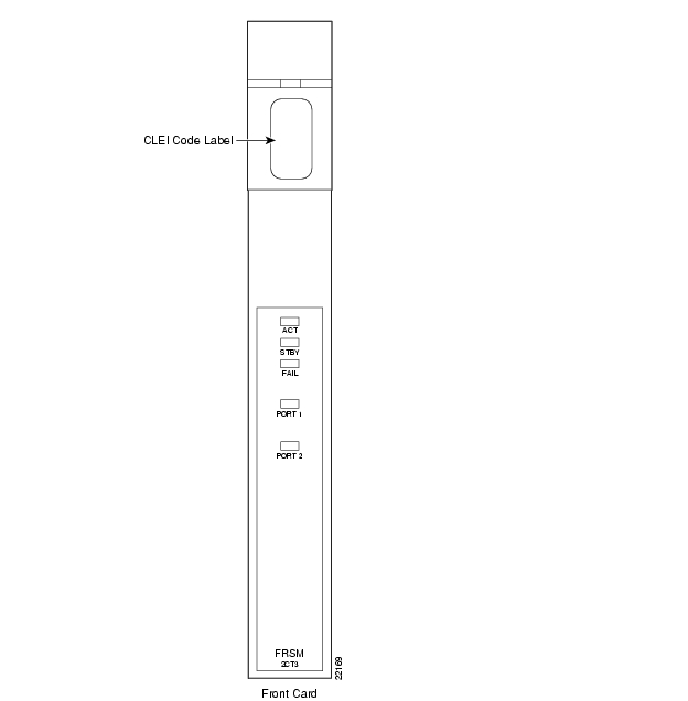
Figure 2-16 MGX-FRSM-2CT3
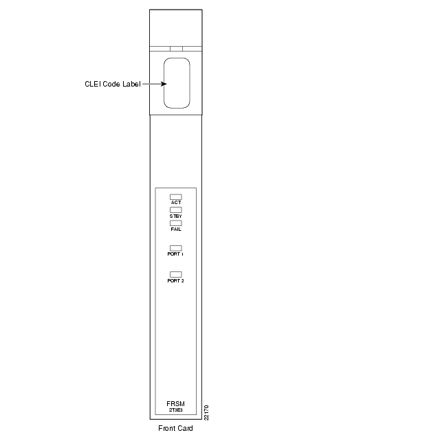
Figure 2-17 MGX-FRSM-2T3E3
Figure 2-18 BNC-2T3
Figure 2-19 BNC-2E3
FRSMs for Serial Connections
The FRSMs that support serial connections include
•
•
FRSM-HS1/B X.21 and V.35 Interfaces
Features specific to the FRSM-HS1/B with X.21 and V.35 interfaces are
•
•
•
•
•
•
•
•
•
FRSM-HS2 HSSI Interfaces
Features specific to the FRSM-HS2 with HSSI interfaces are
•
•
•
•
•
•
•
•
•
Card Combinations
The following card combinations are supported.
•
•
Illustrations
This chapter provides front and back card illustrations as follows.
•
•
•
•
LED Indicators
Table2-9 and Table2-10 describe the FRSM T1/E1 LED faceplate indicators for both the FRSM-HS1/B and the FRSM-HS2
Table2-9 Card Level LED Indicators for the FRSM-HS1/B and the FRSM-HS2
ACT
Green
Active
STBY
Yellow
Standby
FAIL
Red
Fail
.
Table2-10 Line Level LED Indicators for the FRSM-HS1/B and the FRSM-HS2
PORT
Green
Active and OK
Red
Active and Local Alarm
Yellow
Active and Remote Alarm
MGX-FRSM-HS1/B Cabling
The cable models come from the Cisco 12-in-1 series of cables. (See Table2-11.) Each cable can have a male or female connector at the far end. Also, the available clock sources depend on the mode. In DTE mode, the clock source is either line or ST (ST is a wire in the cable). For DCE, the clock source is the front card.
See Table2-12 for the relationship between cabling and modes and Table2-13 for part numbers.
Table 2-11 12IN1-S4 Back Card Cable Types
DCE
X.21 DCE
V.35 DCE
DTE
X.21 DTE
V.35 DTE
Note
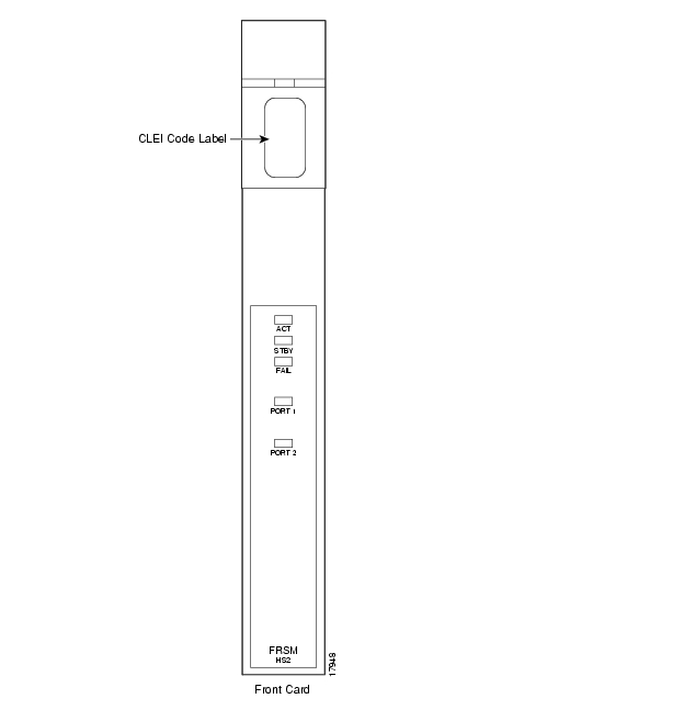
Figure 2-20 MGX-FRSM-HS2
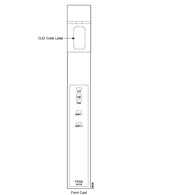
Figure 2-21 MGX-FRSM-HS1/B Front Card Faceplate
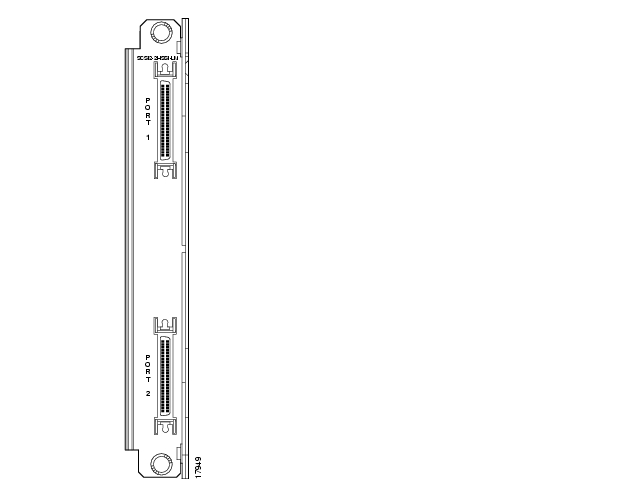
Figure 2-22 SCSI2-2HSSI
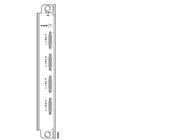
Figure 2-23 12-IN-1 S4 Back Card Faceplate
Circuit Emulation Service Modules
The main function of the Circuit Emulation Service Module (CESM) is to provide a constant bit rate (CBR) circuit emulation service by converting data streams into CBR AAL1 cells for transport across an ATM network. The CESM supports the CES-IS specifications of the ATM Forum.
There are two types of CESM modules:
CESM for T1 and E1 Lines
The eight-port AX-CESM-8T1 and AX-CESM-8E1 models allow individual physical ports to be configured for structured or unstructured data transfer. The CESM provides constant bit rate (CBR) services over an ATM network. It allows circuit-based equipment, such as PBXs, to be interconnected over an ATM backbone via CBR connections. The eight port CESM cards support both channelized (Nx64 Kbps) and unchannelized (T1/E1) circuit-based equipment. In ATM Forum terminology, the terms structured data transfer (SDT) and unstructured data transfer (UDT) are used for channelized and unchannelized circuit emulation, respectively.
In addition, flexible clocking mechanisms are provided to meet different application requirements. Synchronous clocking and asynchronous clocking, using either SRTS or Adaptive clock recovery, are both supported.
As an enhancement, dynamic bandwidth allocation is supported via on-hook/off-hook detection to reduce backbone bandwidth consumed when it is not required by the applications. This allows other traffic streams, such as VBR and ABR traffic, to take advantage of the bandwidth normally reserved for the circuit traffic.
CESM T1 and E1 Features
The eight port CESM cards offer the following features for both T1 and E1 interfaces:
•
•
•
•
•
•
•
•
•
•
•
•
•
•
1:N Redundancy for the CESM T1/E1
Redundancy for the AX-CESM-8T1 and AX-CESM-8E1 is available through the MGX-SRM-3T3/C.
•
•
For information on installation requirements, see the "Service Resource Module" section . For configuration requirements, see the "Service Resource Module" section on page6-60.
For instructions on how to use the CiscoView application to configure redundancy, refer to the CiscoView user-documentation.
Card Combinations
A card set has an AX-CESM-8T1 or AX-CESM-8E1 front card and one of the following back cards:
•
•
•
•
•
CESM T1/E1 Illustrations
•
•
LED Indicators for the Eight-Port CESM
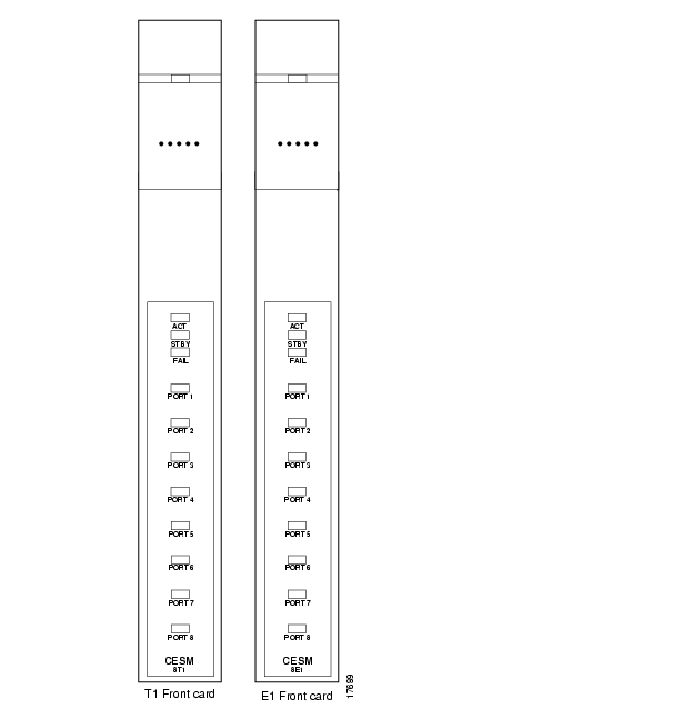
The description of the LEDs on the eight-port CESM (see Table2-14) correspond to the illustration in Figure2-24.
Figure 2-24 Front Cards for the Eight-Port CESM
Figure 2-25 RJ-48 and SMB Back Cards for the MGX-CESM-8T1E1
CESM for T3 and E3 lines
The MGX-CESM-T3/E3 supports unstructured data transfer over a single T3 or E3 physical port at speeds of 44.736 Mbps (T3) or 34.368 Mbps (E3). Only synchronous timing is supported.
MGX-CESM-T3/E3 is a two-card set consisting of a front card and either a T3 back card or an E3 back card. Each back card provides two T3 or E3 ports (each port consisting of two BNC connectors). Only port one is available on the back card when used with the CESM-T3/E3 front card. 1:1 redundancy is supported through a Y-cable on the line module back cards.
•
•
•
CESM-T3/E3 Features
CESM cards support circuit emulation services using standards-based adaptation layers over ATM. The CESM-T3E3 uses AAL1 for T3 or E3 unstructured transfer mode operation, per the ATM Forum's Circuit Emulation Specification, Version 2.0.
•
•
•
•
•
•
•
•
•
T3 Interfaces
The T3 CESM card supports the following T3 interface features.
•
•
•
•
•
•
•
E3 Interfaces
The E3 CESM card supports the following E3 interface features.
•
•
•
•
•
•
•
LED Indicators
CESM T3/E3 Illustrations
This chapter provides illustrations of CESM front and back cards as follows.
•
•
•
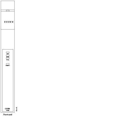
Figure 2-26 CESM-T3/E3 Front Card
Figure 2-27 BNC-2T3 Back Card for the CESM-T3/E3
Note
Figure 2-28 BNC-2E3 Back Card for the CESM-T3/E3
Note
Voice Service—VISM
The Voice Interworking Service Module (VISM) is a front and back card set designed to transport digitized voice signals across a packet network. This provides an interface or gateway between conventional voice TDM networks and networks based upon packet switching technology.
There are two types of VISM front cards:
•
•
VISM Documentation
Installation, configuration, and support for the VISM services are not included in this publication. For more information on the VISM, refer to the following Cisco Systems publications:
•
•
Summary of Features Supported with VISM 1.5.5
The following features are supported with VISM 1.5.5 on the MGX 8250.
VoIP using RTP (RFC 1889)
VISMR1.5 supports standards-based VoIP using RTP (RFC 1889) and RTCP protocols. This allows VISM to interwork with other VoIP Gateways.
VoAAL2 (With sub-cell multiplexing) PVC
The VISM supports standards-compliant AAL2 adaptation for the transport of voice over an ATM infrastructure. AAL2 trunking mode is supported.
Codec Support
G.711 PCM (A-law, Mu-law), G.726, G.729a/b
Eight T1/E1 Interfaces
The VISM supports eight T1 or eight E1 interfaces when G.711 PCM coding is used. For higher complexity coders such as G.726-32K and G.729a-8K, the density drops to six T1 or five E1 interfaces (max 145 channels).
1:N Redundancy
1:N redundancy using SRM.
T3 Interfaces (via SRM bulk distribution)
T3 interfaces are supported using the SRM's bulk distribution capability. In this case, the T3 interfaces are physically terminated at the SRM module. The SRM module breaks out the individual T1s and distributes the T1s via the TDM backplane bus to the individual VISM cards for processing.
Echo Cancellation
The VISM provides on-board echo cancellation on a per-connection basis. Up to 128 msec user-configurable near-end delay can be canceled. The echo cancellation is compliant with ITU G.165 and G.168 specifications.
Voice Activity Detection
VISM uses Voice Activity Detection (VAD) to distinguish between silence and voice on an active connection. VAD reduces the bandwidth requirements of a voice connection by not generating traffic during periods of silence in an active voice connection. At the far-end, comfort noise is generated.
Fax/Modem Detection for ECAN and VAD Control
The VISM continually monitors and detects fax and modem carrier tones. When carrier tone from a fax or modem is detected, the connection is upgraded to full PCM to ensure transparent connectivity. Fax and modem tone detection ensures compatibility with all voice-grade data connections.
CAS Tunneling via AAL2 (for AAL2 Trunking Mode)
The VISM in AAL2 mode facilitates transport of CAS signaling information. CAS signaling information is carried transparently across the AAL2 connection using type 3 packets. In this mode, VISM does not interpret any of the signaling information.
PRI Tunneling via AAL5 (for AAL2 Trunking Mode)
VISM supports transport of D-ch signaling information over an AAL5 VC. The signaling channel is transparently carried over the AAL5 VC and delivered to the far-end. In this mode, VISM does not interpret any of the signaling messages.
Voice CAC
VISM can be configured to administer Connection Admission Control (CAC) so that the bandwidth distribution between voice and data can be controlled in AAL2 mode.
Type 3 Packet for DTMF
The VISM in AAL2 mode facilitates transport of DTMF signaling information. DTMF information is carried transparently across the AAL2 connection using type 3 packets.
Dual (Redundant) PVCs for Bearer/Control
The VISM provides the capability to configure two PVCs for bearer/signaling traffic terminating on two external routers (dual-homing). VISM continually monitors the status of the active PVC by using OAM loopback cells. Upon detection of failure, the traffic is automatically switched over to the backup PVC.
64 K Clear Channel Transport
The VISM supports 64 Kbps clear channel support. In this mode, all codecs are disabled and the data is transparently transported through the VISM.
DTMF Relay for G.729
In VoIP mode, DTMF signaling information is transported across the connection using RTP NSE (Named Signaling Event) packets
MGCP 0.1 for VoIP with Softswitch Control
VISM supports Media Gateway Control Protocol (MGCP) Version 0.1. This open protocol allows any Softswitch to interwork with the VISM module.
Resource Coordination via SRCP
Simple Resource Control Protocol (SRCP) provides a heartbeat mechanism between the VISM and the Softswitch. In addition, SRCP also provides the Softswitch with gateway auditing capabilities.
Full COT Functions
VISM provides the capability to initiate continuity test as well as provide loopbacks to facilitate continuity tests when originated from the far-end.
Courtesy Down
This feature provides a mechanism for graceful upgrades. By enabling this feature, no new calls are allowed on the VISM while not disrupting the existing calls. Eventually, when there are no more active calls, the card is ready for a upgrade and/or service interruption.
Summary of Features Supported with VISM 2.0.1
VISM 2.0.1 supports all of the VISM 1.5.5 features listed above. In addition, VISM 2.0.1 supports the following features:
•
The PRI backhaul capability provides PRI termination on the VISM with the Softswitch providing call control. ISDN Layer 2 is terminated on the VISM and the layer 3 messages are transported to the Softswitch using RUDP.•
Significant improvements have been made to bring the round-trip delay to less than 60 ms.•
VISM provides the capability to have the codecs negotiated between the two end-points of the call. The VISM can be configured, for a given end-point, to have a prioritized list of codecs. Codec negotiation could be directly between the end-points or could be controlled by a Softswitch•
While all 31 DS0s on a E1 port can be used, there is a limitation of 240 channels per card.VISM Redundancy
The VISM redundancy strategy is the same as for any of the eight port cards in the MGX 8250.
•
•
Card Combinations
A card set has an VISM-8T1 or VISM-8E1 front card and one of the following back cards:
•
•
•
•
•
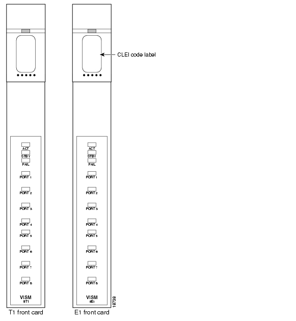
VISM Card Illustrations and LED Description
Table2-16 describes the VISM card LED indicators.
See Figure2-29 for an illustration of the VISM Front Cards.
See Figure2-30 for an illustration of the VISM Back Cards.
Figure 2-29 VISM Front Cards
Figure 2-30 VISM Back Cards
Route Processor Module
The Route Processor Module (RPM) is a Cisco 7200 series router redesigned into a double-height card to fit in a MGX 8250 chassis. The RPM front card provides a Cisco IOS network processing engine (NPE-150), capable of processing up to 120 K packets per second (pps). The front card also provides ATM connectivity to the MGX 8250 internal cell bus at full-duplex OC-3c from the module.
Initially, three types of single-height back card types will be supported: four-port Ethernet, one-port (FDDI), and one-port Fast Ethernet. Each module can support two of these back cards.
The RPM enables high quality, scalable IP+ATM integration using multiprotocol label switching (MPLS) technology.
RPM Documentation
Installation, configuration and support for RPM services are not included in this manual. For more information on the RPM, refer to the following Cisco Systems publications:
•
•
![]()
![]()
![]()
![]()
![]()
![]()
![]()
![]()
Posted: Thu Mar 4 21:05:22 PST 2004
All contents are Copyright © 1992--2004 Cisco Systems, Inc. All rights reserved.
Important Notices and Privacy Statement.