|
|

This chapter describes the steps to take and the considerations you should keep in mind prior to installing the modules in an open rack. It also contains information that applies to an MGX 8250 installation in a Cisco closed rack. If the MGX 8250 arrives in a Cisco closed rack, your initial concerns would be the cabinet grounding, power connections, and optional seismic stability plate.
For specifications on the enclosure and power system, see "System Specifications."
The sections in this chapter are
Before proceeding with the installation, verify that all the ordered parts are present and in good condition. Store a record of the parts and serial numbers. If any parts are missing or damaged, contact your sales representative.
In addition to the power and grounding requirements detailed in subsequent sections, the site must satisfy requirements in the following categories:
 |
Caution If you move a Cisco-supplied cabinet, do not push it at its sides. Push at the front or back. |
This chapter provides regulatory compliance and safety information for the AC and DC powered versions of the MGX 8250.
 |
Warning Only trained service personnel should install the equipment. |
|
Warning Read the installation instructions before you connect the equipment to its power source. |
The MGX 8250 AC and DC powered systems are intended for installation in a RESTRICTED ACCESS LOCATION.
The guidelines that follow help ensure your safety and protect the MGX 8250 equipment. The list of guidelines may not address all potentially hazardous situations in your working environment, so be alert, and exercise good judgement at all times.
The safety guidelines are
|
Warning Before working on a chassis or working near power supplies, unplug the power cords on an AC-powered system. On a DC-powered system, disconnect the power at the circuit breakers. |
Follow these guidelines when working on equipment powered by electricity:
| |||
Waarschuwing | Dit waarschuwingssymbool betekent gevaar. U verkeert in een situatie die lichamelijk letsel kan veroorzaken. Voordat u aan enige apparatuur gaat werken, dient u zich bewust te zijn van de bij elektrische schakelingen betrokken risico's en dient u op de hoogte te zijn van standaard maatregelen om ongelukken te voorkomen. | ||
Varoitus | Tämä varoitusmerkki merkitsee vaaraa. Olet tilanteessa, joka voi johtaa ruumiinvammaan. Ennen kuin työskentelet minkään laitteiston parissa, ota selvää sähkökytkentöihin liittyvistä vaaroista ja tavanomaisista onnettomuuksien ehkäisykeinoista. | ||
Attention | Ce symbole d'avertissement indique un danger. Vous vous trouvez dans une situation pouvant causer des blessures ou des dommages corporels. Avant de travailler sur un équipement, soyez conscient des dangers posés par les circuits électriques et familiarisez-vous avec les procédures couramment utilisées pour éviter les accidents. | ||
Warnung | Dieses Warnsymbol bedeutet Gefahr. Sie befinden sich in einer Situation, die zu einer Körperverletzung führen könnte. Bevor Sie mit der Arbeit an irgendeinem Gerät beginnen, seien Sie sich der mit elektrischen Stromkreisen verbundenen Gefahren und der Standardpraktiken zur Vermeidung von Unfällen bewußt. | ||
Avvertenza | Questo simbolo di avvertenza indica un pericolo. La situazione potrebbe causare infortuni alle persone. Prima di lavorare su qualsiasi apparecchiatura, occorre conoscere i pericoli relativi ai circuiti elettrici ed essere al corrente delle pratiche standard per la prevenzione di incidenti. | ||
Advarsel | Dette varselsymbolet betyr fare. Du befinner deg i en situasjon som kan føre til personskade. Før du utfører arbeid på utstyr, må du vare oppmerksom på de faremomentene som elektriske kretser innebærer, samt gjøre deg kjent med vanlig praksis når det gjelder å unngå ulykker. | ||
Aviso | Este símbolo de aviso indica perigo. Encontra-se numa situação que lhe poderá causar danos físicos. Antes de começar a trabalhar com qualquer equipamento, familiarize-se com os perigos relacionados com circuitos eléctricos, e com quaisquer práticas comuns que possam prevenir possíveis acidentes. | ||
¡Atención! | Este símbolo de aviso significa peligro. Existe riesgo para su integridad física. Antes de manipular cualquier equipo, considerar los riesgos que entraña la corriente eléctrica y familiarizarse con los procedimientos estándar de prevención de accidentes. | ||
Varning! | Denna varningssymbol signalerar fara. Du befinner dig i en situation som kan leda till personskada. Innan du utför arbete på någon utrustning måste du vara medveten om farorna med elkretsar och känna till vanligt förfarande för att förebygga skador. | ||
| |||
Waarschuwing | Dit produkt dient volgens alle landelijke wetten en voorschriften te worden afgedankt. | ||
Varoitus | Tämän tuotteen lopullisesta hävittämisestä tulee huolehtia kaikkia valtakunnallisia lakeja ja säännöksiä noudattaen. | ||
Attention | La mise au rebut définitive de ce produit doit être effectuée conformément à toutes les lois et réglementations en vigueur. | ||
Warnung | Dieses Produkt muß den geltenden Gesetzen und Vorschriften entsprechend entsorgt werden. | ||
Avvertenza | L'eliminazione finale di questo prodotto deve essere eseguita osservando le normative italiane vigenti in materia. | ||
Advarsel | Endelig disponering av dette produktet må skje i henhold til nasjonale lover og forskrifter. | ||
Aviso | A descartagem final deste produto deverá ser efectuada de acordo com os regulamentos e a legislação nacional. | ||
¡Advertencia! | El desecho final de este producto debe realizarse según todas las leyes y regulaciones nacionales. | ||
Varning! | Slutlig kassering av denna produkt bör skötas i enlighet med landets alla lagar och föreskrifter. | ||
| |||
Waarschuwing | Tijdens onweer dat gepaard gaat met bliksem, dient u niet aan het systeem te werken of kabels aan te sluiten of te ontkoppelen. | ||
Varoitus | Älä työskentele järjestelmän parissa äläkä yhdistä tai irrota kaapeleita ukkosilmalla. | ||
Attention | Ne pas travailler sur le système ni brancher ou débrancher les câbles pendant un orage. | ||
Warnung | Arbeiten Sie nicht am System und schließen Sie keine Kabel an bzw. trennen Sie keine ab, wenn es gewittert. | ||
Avvertenza | Non lavorare sul sistema o collegare oppure scollegare i cavi durante un temporale con fulmini. | ||
Advarsel | Utfør aldri arbeid på systemet, eller koble kabler til eller fra systemet når det tordner eller lyner. | ||
Aviso | Não trabalhe no sistema ou ligue e desligue cabos durante períodos de mau tempo (trovoada). | ||
¡Advertencia! | No operar el sistema ni conectar o desconectar cables durante el transcurso de descargas eléctricas en la atmósfera. | ||
Varning! | Vid åska skall du aldrig utföra arbete på systemet eller ansluta eller koppla loss kablar. | ||
| |||
Waarschuwing | Alvorens aan apparatuur te werken die met elektrische leidingen is verbonden, sieraden (inclusief ringen, kettingen en horloges) verwijderen. Metalen voorwerpen worden warm wanneer ze met stroom en aarde zijn verbonden, en kunnen ernstige brandwonden veroorzaken of het metalen voorwerp aan de aansluitklemmen lassen. | ||
Varoitus | Ennen kuin työskentelet voimavirtajohtoihin kytkettyjen laitteiden parissa, ota pois kaikki korut (sormukset, kaulakorut ja kellot mukaan lukien). Metalliesineet kuumenevat, kun ne ovat yhteydessä sähkövirran ja maan kanssa, ja ne voivat aiheuttaa vakavia palovammoja tai hitsata metalliesineet kiinni liitäntänapoihin. | ||
Attention | Avant d'accéder à cet équipement connecté aux lignes électriques, ôter tout bijou (anneaux, colliers et montres compris). Lorsqu'ils sont branchés à l'alimentation et reliés à la terre, les objets métalliques chauffent, ce qui peut provoquer des blessures graves ou souder l'objet métallique aux bornes. | ||
Warnung | Vor der Arbeit an Geräten, die an das Netz angeschlossen sind, jeglichen Schmuck (einschließlich Ringe, Ketten und Uhren) abnehmen. Metallgegenstände erhitzen sich, wenn sie an das Netz und die Erde angeschlossen werden, und können schwere Verbrennungen verursachen oder an die Anschlußklemmen angeschweißt werden. | ||
Avvertenza | Prima di intervenire su apparecchiature collegate alle linee di alimentazione, togliersi qualsiasi monile (inclusi anelli, collane, braccialetti ed orologi). Gli oggetti metallici si riscaldano quando sono collegati tra punti di alimentazione e massa: possono causare ustioni gravi oppure il metallo può saldarsi ai terminali. | ||
Advarsel | Fjern alle smykker (inkludert ringer, halskjeder og klokker) før du skal arbeide på utstyr som er koblet til kraftledninger. Metallgjenstander som er koblet til kraftledninger og jord blir svært varme og kan forårsake alvorlige brannskader eller smelte fast til polene. | ||
Aviso | Antes de trabalhar em equipamento que esteja ligado a linhas de corrente, retire todas as jóias que estiver a usar (incluindo anéis, fios e relógios). Os objectos metálicos aquecerão em contacto com a corrente e em contacto com a ligação à terra, podendo causar queimaduras graves ou ficarem soldados aos terminais. | ||
¡Advertencia! | Antes de operar sobre equipos conectados a líneas de alimentación, quitarse las joyas (incluidos anillos, collares y relojes). Los objetos de metal se calientan cuando se conectan a la alimentación y a tierra, lo que puede ocasionar quemaduras graves o que los objetos metálicos queden soldados a los bornes. | ||
Varning! | Tag av alla smycken (inklusive ringar, halsband och armbandsur) innan du arbetar på utrustning som är kopplad till kraftledningar. Metallobjekt hettas upp när de kopplas ihop med ström och jord och kan förorsaka allvarliga brännskador; metallobjekt kan också sammansvetsas med kontakterna. | ||
| |||
Waarschuwing | U dient de voeding niet aan te raken zolang het netsnoer aangesloten is. Bij systemen met een stroomschakelaar zijn er lijnspanningen aanwezig in de voeding, zelfs wanneer de stroomschakelaar uitgeschakeld is en het netsnoer aangesloten is. Bij systemen zonder een stroomschakelaar zijn er lijnspanningen aanwezig in de voeding wanneer het netsnoer aangesloten is. | ||
Varoitus | Älä kosketa virtalähdettä virtajohdon ollessa kytkettynä. Virrankatkaisimella varustetuissa järjestelmissä on virtalähteen sisällä jäljellä verkkojännite, vaikka virrankatkaisin on katkaistu-asennossa virtajohdon ollessa kytkettynä. Järjestelmissä, joissa ei ole virrankatkaisinta, on virtalähteen sisällä verkkojännite, kun virtajohto on kytkettynä. | ||
Attention | Ne pas toucher le bloc d'alimentation quand le cordon d'alimentation est branché. Avec les systèmes munis d'un commutateur marche-arrêt, des tensions de ligne sont présentes dans l'alimentation quand le cordon est branché, même si le commutateur est à l'arrêt. Avec les systèmes sans commutateur marche-arrêt, l'alimentation est sous tension quand le cordon d'alimentation est branché. | ||
Warnung | Berühren Sie das Netzgerät nicht, wenn das Netzkabel angeschlossen ist. Bei Systemen mit Netzschalter liegen Leitungsspannungen im Netzgerät vor, wenn das Netzkabel angeschlossen ist, auch wenn das System ausgeschaltet ist. Bei Systemen ohne Netzschalter liegen Leitungsspannungen im Netzgerät vor, wenn das Netzkabel angeschlossen ist. | ||
Avvertenza | Non toccare l'alimentatore se il cavo dell'alimentazione è collegato. Per i sistemi con un interruttore di alimentazione, tensioni di linea sono presenti all'interno dell'alimentatore anche quando l'interruttore di alimentazione è en posizione di disattivazione (off), se il cavo dell'alimentazione è collegato. Per i sistemi senza un interruttore, tensioni di linea sono presenti all'interno dell'alimentatore quando il cavo di alimentazione è collegato. | ||
Advarsel | Berør ikke strømforsyningsenheten når strømledningen er tilkoblet. I systemer som har en strømbryter, er det spenning i strømforsyningsenheten selv om strømbryteren er slått av og strømledningen er tilkoblet. Når det gjelder systemer uten en strømbryter, er det spenning i strømforsyningsenheten når strømledingen er tilkoblet. | ||
Aviso | Não toque na unidade abastecedora de energia quando o cabo de alimentação estiver ligado. Em sistemas com interruptor, a corrente eléctrica estará presente na unidade abastecedora, sempre que o cabo de alimentação de energia estiver ligado, mesmo quando o interruptor se encontrar desligado. Para sistemas sem interruptor, a tensão eléctrica dentro da unidade abastecedora só estará presente quando o cabo de alimentação estiver ligado. | ||
¡Advertencia! | No tocar la fuente de alimentación mientras el cable esté enchufado. En sistemas con interruptor de alimentación, hay voltajes de línea dentro de la fuente, incluso cuando el interruptor esté en Apagado (OFF) y el cable de alimentación enchufado. En sistemas sin interruptor de alimentación, hay voltajes de línea en la fuente cuando el cable está enchufado. | ||
Varning! | Vidrör inte strömförsörjningsenheten när nätsladden är ansluten. För system med strömbrytare finns det nätspänning i strömförsörjningsenheten även när strömmen har slagits av men nätsladden är ansluten. För system utan strömbrytare finns det nätspänning i strömförsörjningsenheten när nätsladden är ansluten. | ||
| |||
Waarschuwing | Voordat u aan een frame of in de nabijheid van voedingen werkt, dient u bij wisselstroom toestellen de stekker van het netsnoer uit het stopcontact te halen; voor gelijkstroom toestellen dient u de stroom uit te schakelen bij de stroomverbreker. | ||
Varoitus | Kytke irti vaihtovirtalaitteiden virtajohto ja katkaise tasavirtalaitteiden virta suojakytkimellä, ennen kuin teet mitään asennuspohjalle tai työskentelet virtalähteiden läheisyydessä. | ||
Attention | Avant de travailler sur un châssis ou à proximité d'une alimentation électrique, débrancher le cordon d'alimentation des unités en courant alternatif ; couper l'alimentation des unités en courant continu au niveau du disjoncteur. | ||
Warnung | Bevor Sie an einem Chassis oder in der Nähe von Netzgeräten arbeiten, ziehen Sie bei Wechselstromeinheiten das Netzkabel ab bzw. schalten Sie bei Gleichstromeinheiten den Strom am Unterbrecher ab. | ||
Avvertenza | Prima di lavorare su un telaio o intorno ad alimentatori, scollegare il cavo di alimentazione sulle unità CA; scollegare l'alimentazione all'interruttore automatico sulle unità CC. | ||
Advarsel | Før det utføres arbeid på kabinettet eller det arbeides i nærheten av str¿mforsyningsenheter, skal str¿mledningen trekkes ut p vekselstrømsenheter og strømmen kobles fra ved strømbryteren på likestrømsenheter. | ||
Aviso | Antes de trabalhar num chassis, ou antes de trabalhar perto de unidades de fornecimento de energia, desligue o cabo de alimentação nas unidades de corrente alternada; desligue a corrente no disjuntor nas unidades de corrente contínua. | ||
¡Advertencia! | Antes de manipular el chasis de un equipo o trabajar cerca de una fuente de alimentación, desenchufar el cable de alimentación en los equipos de corriente alterna (CA); cortar la alimentación desde el interruptor automático en los equipos de corriente continua (CC). | ||
Varning! | Innan du arbetar med ett chassi eller nära strömförsörjningsenheter skall du för växelströmsenheter dra ur nätsladden och för likströmsenheter bryta strömmen vid överspänningsskyddet. | ||
| |||
Waarschuwing | Voordat u aan een systeem werkt dat een aan/uit schakelaar heeft, dient u de stroomvoorziening UIT te schakelen en de stekker van het netsnoer uit het stopcontact te halen. | ||
Varoitus | Ennen kuin teet mitään sellaiselle järjestelmälle, jossa on kaksiasentokytkin, katkaise siitä virta ja kytke virtajohto irti. | ||
Attention | Avant de travailler sur un système équipé d'un commutateur marche-arrêt, mettre l'appareil à l'arrêt (OFF) et débrancher le cordon d'alimentation. | ||
Warnung | Bevor Sie an einem System mit Ein/Aus-Schalter arbeiten, schalten Sie das System AUS und ziehen das Netzkabel aus der Steckdose. | ||
Avvertenza | Prima di lavorare su un sistema dotato di un interruttore on/off, spegnere (OFF) il sistema e staccare il cavo dell'alimentazione. | ||
Advarsel | Slå AV strømmen og trekk ut strømledningen før det utføres arbeid på et system som er utstyrt med en av/på-bryter. | ||
Aviso | Antes de começar a trabalhar num sistema que tem um interruptor on/off, DESLIGUE a corrente eléctrica e retire o cabo de alimentação da tomada. | ||
¡Advertencia! | Antes de utilizar cualquier sistema equipado con interruptor de Encendido/Apagado (ON/OFF), cortar la alimentación y desenchufar el cable de alimentación. | ||
Varning! | Slå AV strömmen och dra ur nätsladden innan du utför arbete på ett system med strömbrytare. | ||
| |||
Waarschuwing | Deze apparatuur hoort geaard te worden Zorg dat de host-computer tijdens normaal gebruik met aarde is verbonden. | ||
Varoitus | Tämä laitteisto on tarkoitettu maadoitettavaksi. Varmista, että isäntälaite on yhdistetty maahan normaalikäytön aikana. | ||
Attention | Cet équipement doit être relié à la terre. S'assurer que l'appareil hôte est relié à la terre lors de l'utilisation normale. | ||
Warnung | Dieses Gerät muß geerdet werden. Stellen Sie sicher, daß das Host-Gerät während des normalen Betriebs an Erde gelegt ist. | ||
Avvertenza | Questa apparecchiatura deve essere collegata a massa. Accertarsi che il dispositivo host sia collegato alla massa di terra durante il normale utilizzo. | ||
Advarsel | Dette utstyret skal jordes. Forviss deg om vertsterminalen er jordet ved normalt bruk. | ||
Aviso | Este equipamento deverá estar ligado à terra. Certifique-se que o host se encontra ligado à terra durante a sua utilização normal. | ||
¡Advertencia! | Este equipo debe conectarse a tierra. Asegurarse de que el equipo principal esté conectado a tierra durante el uso normal. | ||
Varning! | Denna utrustning är avsedd att jordas. Se till att värdenheten är jordad vid normal användning. | ||
| |||
Waarschuwing | Raadpleeg de installatie-aanwijzingen voordat u het systeem met de voeding verbindt. | ||
Varoitus | Lue asennusohjeet ennen järjestelmän yhdistämistä virtalähteeseen. | ||
Attention | Avant de brancher le système sur la source d'alimentation, consulter les directives d'installation. | ||
Warnung | Lesen Sie die Installationsanweisungen, bevor Sie das System an die Stromquelle anschließen. | ||
Avvertenza | Consultare le istruzioni di installazione prima di collegare il sistema all'alimentatore. | ||
Advarsel | Les installasjonsinstruksjonene før systemet kobles til strømkilden. | ||
Aviso | Leia as instruções de instalação antes de ligar o sistema à sua fonte de energia. | ||
¡Atención! | Ver las instrucciones de instalación antes de conectar el sistema a la red de alimentación. | ||
Varning! | Läs installationsanvisningarna innan du kopplar systemet till dess strömförsörjningsenhet. | ||
| |||
Waarschuwing | Klasse-1 laser produkt. | ||
Varoitus | Luokan 1 lasertuote. | ||
Attention | Produit laser de classe 1. | ||
Warnung | Laserprodukt der Klasse 1. | ||
Avvertenza | Prodotto laser di Classe 1. | ||
Advarsel | Laserprodukt av klasse 1. | ||
Aviso | Produto laser de classe 1. | ||
¡Advertencia! | Producto láser Clase I. | ||
Varning! | Laserprodukt av klass 1. | ||
| |||
Waarschuwing | Niet in de straal staren of hem rechtstreeks bekijken met optische instrumenten. | ||
Varoitus | Älä katso säteeseen äläkä tarkastele sitä suoraan optisen laitteen avulla. | ||
Attention | Ne pas fixer le faisceau des yeux, ni l'observer directement à l'aide d'instruments optiques. | ||
Warnung | Nicht direkt in den Strahl blicken und ihn nicht direkt mit optischen Geräten prüfen. | ||
Avvertenza | Non fissare il raggio con gli occhi né usare strumenti ottici per osservarlo direttamente. | ||
Advarsel | Stirr eller se ikke direkte p strlen med optiske instrumenter. | ||
Aviso | Não olhe fixamente para o raio, nem olhe para ele directamente com instrumentos ópticos. | ||
¡Advertencia! | No mirar fijamente el haz ni observarlo directamente con instrumentos ópticos. | ||
Varning! | Rikta inte blicken in mot strålen och titta inte direkt på den genom optiska instrument. | ||
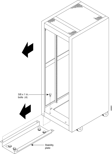
To secure a Cisco-supplied cabinet, holes in the upper and lower corners accommodate 3/8-inch or 1/2-inch bolts. Also, an optional stability plate can be purchased with the Cisco cabinet. The stability plate is bolted to the floor, then the Cisco cabinet is bolted to the stability plate. Instructions for installing the stability plate are in the ""Seismic Anchoring for a Cisco Rack" section."
This section describes how to install the Cisco cabinet with the optional stability plate for seismic anchoring. If you have no stability plate, go to "Enclosure and Card Installation"
To set up the Cisco cabinet with the stability plate, perform the following steps:
Step 1 Use the dimensions in Figure 3-1 to drill the holes for installing the stability plate.
Step 2 Remove the stability plate from the base of the Cisco cabinet. Save these nuts and bolts.
Step 3 With the user-provided anchoring bolts, attach the stability plate to the floor.
Step 4 Roll the Cisco cabinet over the stability plate as Figure 3-2 illustrates.
Step 5 Use the nuts and bolts from the shipping setup to secure the cabinet to the stability plate.

This section describes the requirements for electrical power and grounding the switch and the site. These requirements apply to the Central Office (CO) and the Private Enterprise (PE) sites.
The MGX 8250 uses a 20A, 2-pole circuit breaker for each AC input. The manufacturer of this circuit breaker is ETA. The ETA part number is 8340-F120-P1P2-B2H020A.
DC-powered nodes use a 60A, 1-pole circuit breaker with a short trip delay on each -48V input.
The MGX 8250 AC power requirement are 220 VAC with a worst-case range of 180-240 VAC or
110 VAC with a worst case range 100-240 VAC. See also "System Specifications." The AC power source must be within 6 feet (1.8 m) of the system and easily accessible. Before turning on the power, verify that the power supplied to the node comes from a dedicated branch circuit.
The 110 VAC power supply has a maximum output power of 1200W per power supply module. However, because of safety limitation imposed on the line cord, the 110 VAC power supply output power is shown in Table 3-1.
| Input voltage (Volts AC) | Power output (Watts) |
|---|---|
100 | 900 |
110 | 1000 |
120 | 1100 |
130-264 | 1200 |
The 220 VAC power supply module has a maximum power output of 2500W with two fan trays and 1500W with one fan tray.
 |
Note If the power requirement of the installed cards exceed the power capability of the system, an error message is generated. |
|
Caution Consult Cisco TAC if the plans for the MGX 8250 AC power include a portable, uninterruptible power source (UPS). Cisco recommends a UPS with a low output impedance and the capacity to provide the necessary fault current to trip the protection devices. Do not use a UPS or any power source with a Ferro-Resonant transformer. |
The power receptacles to which the node connects must be of the grounding type. The grounding conductors that connect to the receptacles should connect to protective earth at the service equipment. For reference, Figure 3-3 shows the electrical relationship in the three-wire wall plug.
Cisco can provide 220 VAC power cords with the following plugs:

This section describes the safety and standards-body compliance issues for DC-powered systems. For the bonding and grounding issues related to electrical noise, see the "Bonding and Grounding" section that follows.
The DC-power model of the MGX 8250 uses one or two power entry modules (PEMs) to accept DC current. The DC PEMs should connect to a source capable of supplying 60A of current. Each branch circuit at the source should have a 60A circuit breaker, and the wires connecting the PEMs to the sources should be capable of carrying 60A. A 6 AWG (10 square millimeters) copper wire is adequate. Also, consult the local or national codes for conductor sizing for DC supply connections if necessary. Conductors must be suitable for 60A.
Be sure to connect the grounding wire conduit to a solid earth ground. Cisco recommends a closed loop to terminate the ground conductor at the ground stud.
In summary, note the following guidelines for DC systems:
|
Caution This equipment has a connection between the earth conductor of the DC power supply circuit and the earthing conductor. |
This equipment must be connected directly to the DC supply system earthing electrode conductor or to a bonding jumper from an earthing terminal bar or bus to which the DC supply system earthing electrode is connected.
This equipment must be located in the same immediate area (such as adjacent cabinets) as any other equipment that has a connection between the earthed conductor to the same DC supply circuit and the earthing connector and also the point of earthing of the DC system. The DC system must not be earthed elsewhere.
The DC supply source is to be located within the same premises as this equipment. Switching or disconnecting devices must not be in the earthed circuit conductor between the DC source and the point of the connection of the earthing electrode conductor.
At the input of each power entry module (PEM) in an MGX 8250 node, connect only a -48 VDC source that complies with the Safety Extra Low Voltage (SELV) requirements in UL 1950, EC 950, EN 60950, and CSA C22.2 No. 950-95.
A DC-powered MGX 8250 node should be installed in a restricted access location. In the United States, restricted access is defined in Articles 10-116, 10-117, and 10-118 of the National Electrical Code ANSI/NFPA 70.
To maintain the full EMI and EMC integrity of this equipment, it must be bonded to an integrated ground plane or a non isolated ground plane network. The purpose is to mitigate the damaging effects of electrostatic discharge or lightning. Refer to the latest edition of the ITU-T Recommendation K.27 or Bellcore GR-1089-CORE to ensure that the correct bonding and grounding procedures are followed. As recommended in these documents, a frame bonding connection is provided on the Cisco cabinet for rack-mounted systems. To see how to make a connection, see the "Making the Frame Bonding (Ground) Connection" section later in this chapter.
Except for the AC power supply modules, every module in a rack-mount system uses the rack for grounding. Therefore, the rack must connect to protective earth ground and the equipment must be secured to the rack so as to ensure good bonding.
A DC-powered node must have grounding conductors that connect at two separate locations:
For DC-powered systems, Cisco has designed the MGX 8250 node and other WAN switches to connect to a non isolated ground system. In contrast, routers and other LAN equipment often use an isolated grounding scheme. If wired together through an equalization connection as described in the ITU-T recommendation K.27, the isolated and non isolated ground systems can form a mixed grounding system. The potential between any points in the ground system—whether or not the ground system is mixed—must not exceed 2 percent of the referenced voltage (2 percent of 48V is 960 millivolts).
A mixed ground system appears in Figure 3-4. This figure shows safety and earth grounds and the primary and redundant DC sources Battery A and Battery B. Individual ground conductors are labeled Z1 to Z5. The Z represents the impedance of the ground conductor between a chassis, for example, and a connection to the building's ground system. The numbers 1 to 4 represent building ground points and indicate that an impedance can exist between different points in the ground system of the building. Each of these symbols indicate that a voltage drop may result (but must not exceed 2 percent of the referenced voltage). See Table 3-2 for a definition of each Z1 to Z5.
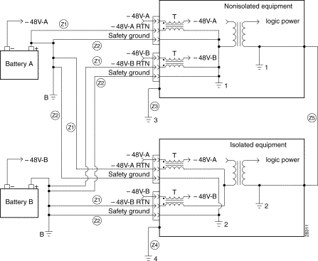
| Connection | Description |
|---|---|
Z1 | -48 VDC return. |
Z2 | Protective earth or safety ground (green/yellow). |
Z3 | Equipment ground for non isolated equipment. |
Z4 | Equipment ground for isolated equipment. |
Z5 | Equalizing frame ground. This ground creates low-impedance equalization between frames. |
B | Battery ground. |
1, 2, 3, 4 | Connection points to the building's ground system—A potential can exist between these points within the ground system. |
T | Common-mode EMI filters. |
As Figure 3-4 shows, the non isolated system has a 48 VDC return that internally connects to the backplane. (This design calls for a hard-wired return and so does not allow for an optional or alternate ground connection.) The internal connection provides a low-impedance connection between 48 VDC return and frame ground. This grounding scheme protects the signals on the backplane from corruption by transients that can result from lightning or electrostatic discharge.
To improve protection against transients, the loop area (and resultant loop impedance) should be made as small as possible by locating the -48 VDC supply, 48 VDC return, and protective earth conductors as close to each other as possible.
As recommended in ITU-T K.27, the multi point grounding in a mesh bonding network provides the best protection for equipment by providing the lowest impedance in the ground system. For more detailed information, refer to the recommendation itself.
To prevent signal degradation, a conductor must be large enough to prevent its impedance from creating a voltage drop equal to 2 percent of the reference voltage. Also, the protective earth conductor must be large enough to carry all the current if the 48 VDC return fails. This latter requirement is for safety. Full fault redundancy is achieved by having equal size conductors for the protective earth ground and the
48 VDC return of the switch.
For wire gauges that prevent unacceptable voltage drops over different lengths of copper wire, see Table 3-3. For the resistance of 1000 feet of copper wire for each gauge of wire, see Table 3-4. These references are for planning purposes and may be further subject to local laws and practices.
| DC Current | Distance in Feet | ||||||
|---|---|---|---|---|---|---|---|
| 25 feet | 50 feet | 75 feet | 100 feet | 150 feet | 200 feet | 400 feet |
5A | 18 | 14 | 14 | 12 | 10 | 8 | 6 |
10A | 14 | 12 | 10 | 8 | 8 | 6 | 2 |
15A | 14 | 10 | 8 | 8 | 6 | 4 | 2 |
20A | 12 | 8 | 8 | 6 | 4 | 2 | 0 |
25A | 12 | 8 | 6 | 4 | 4 | 2 | 0 |
30A | 10 | 8 | 6 | 4 | 2 | 2 | 00 |
35A | 10 | 6 | 4 | 2 | 2 | 1 | 000 |
40A | 8 | 6 | 2 | 2 | 2 | 0 | 000 |
45A | 8 | 6 | 4 | 2 | 1 | 0 | 0000 |
50A | 8 | 4 | 4 | 2 | 1 | 00 | — |
55A | 8 | 4 | 2 | 2 | 0 | 00 | — |
60A | 8 | 4 | 2 | 2 | 0 | 00 | — |
65A | 6 | 4 | 2 | 1 | 0 | 000 | — |
70A | 6 | 4 | 2 | 1 | 00 | 000 | — |
75A | 6 | 4 | 2 | 1 | 00 | 000 | — |
100A | 4 | 2 | 1 | 00 | 000 | — | — |
| Gauge | Ohms per 1000 Feet | Gauge | Ohms per 1000 Feet |
|---|---|---|---|
0000 | 0.0489 | 10 | 0.9968 |
000 | 0,0617 | 11 | 1.257 |
00 | 0.0778 | 12 | 1.5849 |
0 | 0.098 | 13 | 1.9987 |
1 | 0.1237 | 14 | 2.5206 |
2 | 0.156 | 15 | 3.1778 |
3 | 0.1967 | 16 | 4.0075 |
4 | 0.248 | 17 | 5.0526 |
5 | 0.3128 | 18 | 6.3728 |
6 | 0.3944 | 19 | 8.0351 |
7 | 0.4971 | 20 | 10.1327 |
8 | 0.6268 | 21 | 12.7782 |
9 | 0.7908 | 22 | 16.1059 |
The MGX 8250 ships with a wrist strap for grounding the user and protecting the electronic components from electrostatic shock. The wrist strap kit consists of a strap, a coiled cord, and a clip for holding the strap.
Step 1 Cisco recommends you install the base of the wrist strap cable on the left front flange of one of the units at a convenient height.
Step 2 Use a front mounting screw to secure the ring lug to the flange and front rail. The other end of the cord connects to the strap with a snap connector.
Step 3 Peel the back off the clip to expose the adhesive surface and attach to the front of the unit above the ring lug.
Step 4 Mount the clip sideways to allow the strap to be held in a position that will not interfere with the removal of the number card. Use the clip to store the strap.
Different Cisco products can reside in the same rack. If a multi system rack configuration includes a BPX 8600 series switch, it should reside as the bottom unit.
This section describes the steps for making ground connections that comply with the Cisco grounding policies. The descriptions cover optional ground connections from each node to the ground connector of the rack as well as the equalization connections between racks that are part of the earth grounding network.
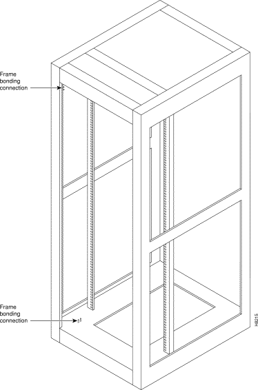
The Cisco-supplied cabinet has two pairs of grounding studs and the hardware for securing a ground conductor to the studs at the top and bottom of the cabinet. The studs measure 1/4-inch by 20 threads per inch. The studs can accept the two-holed grounding connector designed to prevent rotation and possible loosening of the connector. Figure 3-5 shows the Cisco cabinet with the ground attachment studs in the upper and lower parts of the cabinet. A ground symbol on the Cisco rack indicates the points of attachment.
Cisco recommends the following steps for attaching a ground conductor to the frame of a Cisco rack:
Step 1 Place an external, toothed star washer onto the stud.
Step 2 Place the connector terminating the grounding conductor closed-loop ring or two-hole compression fitting onto the stud.
Step 3 Place another external, toothed star washer or lock washer onto the stud.
Step 4 Screw a nut onto the threaded stud.
![]()
![]()
![]()
![]()
![]()
![]()
![]()
![]()
Posted: Sat Sep 7 06:42:50 PDT 2002
All contents are Copyright © 1992--2002 Cisco Systems, Inc. All rights reserved.
Important Notices and Privacy Statement.