cc/td/doc/product/wanbu/mgx8250/1_1_31
hometocprevnextglossaryfeedbacksearchhelp
PDF

Table Of Contents

Introducing the MGX 8250

MGX 8250 System Overview

Applications of the MGX 8250

Universal Edge Architecture

Card Slot Locations

Standards-Based Conversion to ATM

MGX 8250 Enclosure and Power

MGX 8250 Management

Summary of MGX 8250 Cards and Modules

Redundancy for Service Modules

Introducing the MGX 8250


This chapter contains an introduction to the Cisco MGX 8250 Edge Concentrator and includes a summary of product features and equipment.

For more detailed descriptions of the Service Modules, cards and services, please refer to "Module and Service Descriptions"

This chapter contains the following information:

MGX 8250 System Overview

Applications of the MGX 8250

Universal Edge Architecture

Standards-Based Conversion to ATM

MGX 8250 Enclosure and Power

MGX 8250 Management

Summary of MGX 8250 Cards and Modules

Processor Switching Module (PXM1)

Redundancy for Service Modules

Redundancy for Service Modules

Frame Service Modules

ATM UNI Service Modules (AUSM)

Circuit Emulation Service Modules (CESM)

Voice Interworking Service Modules (VISM)

Route Processor Module (RPM)

Redundancy for Service Modules

MGX 8250 System Overview

The MGX 8250 is a highly flexible IP+ATM narrowband edge concentrator for high-density aggregation of IP, voice, Frame Relay, circuit emulation and ATM services. The MGX 8250 can act as a stand-alone edge concentrator or as a feeder node for the Cisco BPX 8600 series and MGX 8850 switches. The MGX8250 Edge Concentrator offers up to 1.2 Gbps of IP + ATM switching capacity.

The Cisco MGX 8250 edge concentrator supports the following services:

IP VPNs using Cisco IOS software-based MPLS/label switching.

The full suite of voice-over-IP, voice-over-ATM, and capabilities with full interworking.

Frame Relay services.

High-density Point-to-Point Protocol (PPP) for Internet access and aggregation.

Narrowband ATM for managed data, voice, and video services.

Circuit Emulation (CE) for private line replacement.

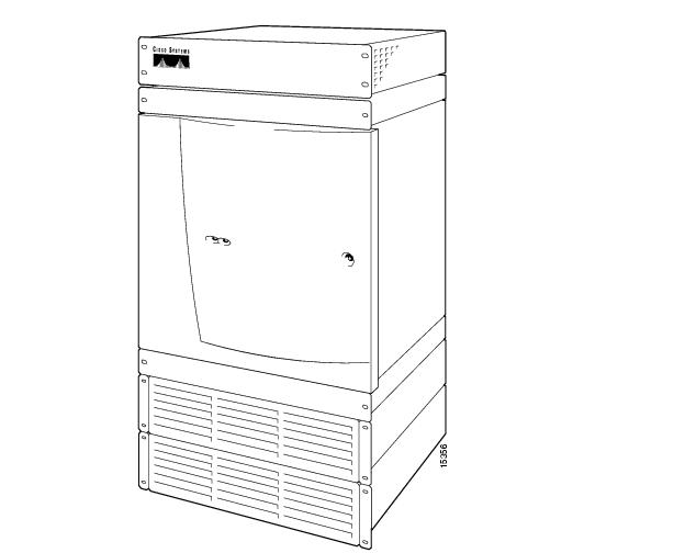
Figure1-1 is an illustration of an AC-powered MGX 8250.

Figure 1-1 MGX 8250

Applications of the MGX 8250

The MGX 8250 operates with the applications listed in Table1-1.

Table1-1 MGX 8250 Applications

Application
Description

Feeder

The MGX8250 concentrates narrow-band and medium-band ATM, Frame Relay, and into a single, wide-band ATM feeder trunk that connects to a BPX 8600 series switch or a MGX8850 switch.

Stand-alone Switch

The MGX 8250 can be deployed as a stand-alone switch, providing "cross-connect" connections between UNI and NNI ports. Traditionally, this would be used in a concentration-type mode, allowing standards-based adaptation and concentration of multiservice traffic onto one or more high-speed ATM interfaces. This enables the MGX 8250 to interface to a multivendor ATM network, or to any other ATM attached device (such as a Cisco 7200 or GSR router LS1010, MSR 8450, and so on). The MGX8250 interfaces to the ATM equipment using a standard ATM UNI or NNI.

Multiprotocol Label Switch

As a component of the BPX 8680-IP universal service node, the MGX 8250 is capable of forwarding traffic into the BPX Multiprotocol Label Switching (MPLS) network by acting as a multiservice feeder

Consolidation of Cisco CPE Traffic

At the edge of the network, the MGX 8250 can interwork with and consolidate a wide variety of CPE equipment.

Mulitservice Stand-alone Concentrator

The MGX 8250 can be deployed as a stand-alone concentrator, interfacing to a multivendor ATM (non-BPX) network, as shown Figure 1-5. The MGX 8250 interfaces to ATM equipment using a standard ATM UNI or NNI.


Note Refer to the Cisco MGX 8250 Edge Concentrator Overview for additional information on the applications of the MGX 8250.


Note See "Configuring the MGX 8250 Shelf" for information on configuring the MGX8250 applications.


Universal Edge Architecture

The MGX 8250 supports a wide range of services over narrowband and mid-band user interfaces by mapping all service traffic to and from ATM using standardized interworking methods.

The supported interfaces for user-traffic are

Frame Relay UNI on T3, E3, HSSI, T1, and E1 lines.

ATM UNI and FUNI interfaces.

Optional inverse multiplexing for ATM (IMA).

Frame Relay to ATM network interworking and service interworking.

Circuit Emulation services for T1/E1 and T3/E3 lines.

The optional Service Resource Module-3T3 (MGX-SRM-3T3/C) can support up to 80 T1 interfaces over its three T3 lines. The MGX-SRM-3T3/C can also provide 1:N redundancy for the T1 and E1 line cards.

The modular, software-based system architecture enables the MGX 8250 to support new features through downloadable software upgrades or new hardware modules.

The MGX 8250 backplane supports individual line rates range from DS0 through OC-12.

Card Slot Locations

The reserved slots are 7 and 8 for the primary and redundant Processor Switching Modules (PXM1s) and 15, 16, 31, and 32 for the Service Resource Modules (SRMs). These slot reservations reflect a fully redundant configuration for these cards. The maximum number of slots remaining for service modules is 24—less when the unit contains one or more double-height cards such as the Route Processor Module (RPM). Also, although not reserved, slots 9 and 10 should be the first choices for the location of one or more RPMs due to backplane wiring.

If you are considering any future card changes in which you replace a single-height card with a double-height card, place the single-height replacement candidates as far left in the card cage as possible. The reason is that single to double-height slot conversions must begin at the left and proceed to the right.

The slots on the top half of the card cage are suitable for the T3/E3 and OC-3 cards because the higher speed cell buses reside in the upper portion of the backplane. Place the service modules that operate at T1 or E1 rates in the lower half of the switch.

Standards-Based Conversion to ATM

The MGX 8250 converts all user information into 53-byte ATM cells by using the appropriate ATM Adaptation Layer (AAL) for transport over the ATM backbone network. The individual service modules segment and reassemble (SAR) cells to eliminate system bottlenecks. The following list shows the applicable AAL for each service:

Circuit emulation services uses AAL1.

Frame Relay-to-ATM network interworking uses AAL5 and Frame Relay Service Specific Convergence Sub-layer (FR-SSCS).

Frame Relay-to-ATM service interworking uses both transparent and translation modes to map Frame Relay to native ATM AAL5.

Frame Forwarding uses AAL5.

MGX 8250 Enclosure and Power

The MGX8250 enclosure contains up to 24-service modules (I/O cards). In addition, up to four optional Service Redundancy Modules (SRMs) provide redundancy. The MGX8250 resides in either in a 19-inch or a 23-inch rack. The 19-inch Cisco-built rack also has an optional seismic anchor. The system can accept power from either a DC or an AC source (see Table1-2).

Table 1-2 Power Supply Options

Model
Description

MGX-DC

MGX 8250 DC PEM and MBX-CAB-AC/DC

MGX-AC1-1

NR AC system for MGX 8250—AC shelf, 1 feed, 1 PS, MGX-CAB-AC/DC

MGX-AC2-2

Red AC pwr, red AC feed, AC shel, 2 PS, 2 MGX-CAB-AC/DC

PS-1200-AC

1200W power supply for AC systems


"Site Preparation" and Chapter4, "Enclosure and Card Installation" contain additional information on installing racks and the MGX 8250 chassis.

MGX 8250 Management

Firmware on each card determines the functions and operations of the module. This firmware can be upgraded by downloading new firmware with a TFTP application running on a workstation or a PC.

The current status and configuration parameters of the modules reside in a Management Information Base (MIB). The MIB is updated by the firmware in the modules whenever changes to the module status or configuration occur. The MIB can be interrogated using SNMP commands.

The MGX 8250 supports the following user interface applications:

Cisco WAN Manager (formerly StrataView Plus)—Graphical User Interface (GUI) application for connection management. This application enables operations, administration, and maintenance of WAN-multiservice networks.

CiscoView—GUI application for hardware configuration.

Command line interface (CLI)—This is used for low-level control of hardware functionality and connection control.

The following ports are used to communicate with the MGX8250:

Control port (SLIP protocol only) on the PXM1-UI back card.

LAN (Ethernet) port on the PXM1-UI back card.

In-band ATM connection (feeder application only).

All of these ports support access by the CLI via Telnet, TFTP, and SNMP.


Note See the "User Interface Access Ports" section for additional information on the ports used to manage and configure the MGX8250.


Summary of MGX 8250 Cards and Modules

This section contains a summary of the service cards and modules supported by the MGX 8250.

For more detailed descriptions and illustrations of cards, modules and the services they provide, see "Module and Service Descriptions".

Introduction to Core Card Sets and Service Modules

The MGX 8250 supports core cards and service modules. The Processor Switching Module (PXM1) and optional Service Resource Module (SRM) are core cards.

In addition, the PXM1 is part of a card set consisting of a front card, a back card, and a daughter card:

The front card contains the processing intelligence.

The back card is a simple card that provides the electrical interface for one or more lines of a particular type.

The daughter card contains the firmware that distinguishes the interface (OC-3, T3, E3, and so on).

Service modules are not combined in this manner and are never part of a card set. Instead, service modules provide the interface for transport technologies such as Frame Relay and ATM.

The MGX 8250 enclosure contains up to 24 service modules (I/O cards). Four optional Service Redundancy Modules (SRMs) provide redundancy.


Note Although technically distinct, the terms card and module are often used interchangeably.


Processor Switching Module (PXM1)

The MGX 8250 cards (modules) and their functions are described in Table1-3.

Table1-3 MGX 8250 Modules and Cards

Modules
Description

Processor Switching Module (PXM1)

This front card controls the MGX 8250 and supports external interfaces for user-access and trunking for UNI ports. The back cards consist of a user interface and a broadband network module.

User Interface Back Cards

Processor Switch Module User Interface (PXM1-UI)
The PXM1-UI is the user interface card that has various types of user access used to control and configure the MGX 8250.

Processor Switch Module User Interface (PXM-UI-S3)
The PXM-UI-S3 is an optional user interface card that has various types of user access used to control and configure the MGX 8250. This card also provides Stratum 3 clocking capability.

User Interface Back Cards

OC-3 Uplink Back Cards

MGX-MMF-4-155/B (multimode fiber uplink back card)
The MGX-MMF-4-155/B is a broadband network module for the PXM1 and provides four SONET OC-3/STM-1 ATM interfaces at 155 Mbps.

MGX-SMFIR-4-155/B (single-mode fiber intermediate reach uplink back card)
The MGX-SMFIR-4-155/B is a broadband network module for the PXM1 and provides a single-mode, intermediate-reach, fiber optic SONET OC-3 interface that conforms to ANSI T1.105 and GR-253-CORE standards. This interface uses SC connectors. Redundant configurations are supported through SONET APS functionality (APS requires the "B" model).

MGX-SMFLR-4-155/B (single-mode fiber long reach uplink back card)
The MGX-SMFLR-4-155/B is a broadband network module for the PXM1 and provides a single-mode, long-reach, fiber optic SONET OC-3 interface that conforms to ANSI T1.105 and GR-253-CORE standards. This interface uses SC connectors, and redundant configurations are supported through SONET APS functionality (APS requires the "B" model).

OC-12 Uplink Back Cards

MGX-SMFIR-1-622
The MGX-SMFIR-1-622 is a broadband network module for the PXM1 and provides a SONET OC-12/STM-4 ATM interface at 622 Mbps. APS requires the "B" model (SMFIR-1-622/B).

MGX-SMFLR-1-622
The MGX-SMFLR-1-622 is a broadband network module for the PXM1 and provides a SONET OC-12/STM-4 ATM interface at 622 Mbps. APS requires the "B" model (SMFLR-1-622/B).

T3/E3 Uplink Back Cards

MGX-BNC-2T3
The MGX-BNC-2T3 is a broadband network module for the PXM1 and provides two-T3 ATM interfaces.

MGX-BNC-2E3
The MGX-BNC-2E3 is a broadband network module for the PXM1 and provides two-E3 ATM interfaces. Two versions of the BNC-2E3 card are available. The BNC-2E3A applies to Australia only. The BNC-2E3 applies to all other sites that require E3 lines on the PXM1 uplink card.

Service Resource Module (SRM)

Service Resource Module (MGX-SRM-3T3/C)
The optional SRM provides three major functions for service modules; bit error rate tester (BERT) of T1 and E1 lines and ports, loops back of individual Nx64 channels toward the customer premises equipment (CPE), and 1:N redundancy for the service modules.

Frame Service Module (FRSM)

Frame Service Modules

Frame Service Module for eight T1 ports (AX-FRSM-8T1)
The AX-FRSM-8T1 provides interfaces for up to eight fractional T1 lines, each of which can support one-56 kbps or one-Nx64 kbps FR-UNI, FR-NNI port, ATM-FUNI, or a Frame forwarding port. The AX-FRSM-8T1 supports fractional and unchannelized T1 port selection on a per-T1 basis.

Frame Service Module for eight E1 ports (AX-FRSM-8E1)
The AX-FRSM-8E1 provides interfaces for up to eight fractional E1 lines, each of which can support one-56 kbps or one-Nx64 kbps FR-UNI, FR-NNI, ATM-FUNI, or Frame forwarding port. The AX-FRSM-8E1 supports fractional and unchannelized E1 port selection on a per-E1 basis.

Frame Service Module for eight channelized T1 ports (AX-FRSM-8T1-C)
The AX-FRSM-8T1-C allows full DS0 and nxDS0 channelization of the T1s and E1s, for a maximum of 192 ports per FRSM-8T1-C. Using the FRSM-8T1-C, up to 192 fully channelized T1 lines can be operated simultaneously on the Cisco MGX 8250 platform.

Frame Service Module for eight channelized E1 ports (AX-FRSM-8E1-C)
The AX-FRSM-8E1-C allows full DS0 and n x DS0 channelization of the E1s, for a maximum of 248 ports per FRSM-8E1-C. Using the FRSM-8E1-C, up to 192 fully channelized E1 lines can be operated simultaneously on the Cisco MGX platform.

Frame Service Module for T3 and E3 (MGX-FRSM-2E3T3)
The MGX-FRSM-2E3/T3 provides interfaces for two-T3 or two-E3 Frame Relay lines, each of which can support either two-T3 lines (each at 44.736 Mbps) or two-E3 lines (each at 34.368 Mbps) FR-UNI, ATM-FUNI, or Frame Forwarding port.

Frame Service Module for channelized T3 (MGX-FRSM-2CT3)
The MGX-FRSM-2CT3 supports interfaces for two-T3 channelized Frame Relay lines. Each interface supports 56 Kbps, 64 Kbps, Nx56 Kbps, Nx64 Kbps, T1 ports for a total of 256 ports that can be freely distributed across the two T3 lines.

Frame Service Module for high speed serial (MGX-FRSM-HS1/B)
The FRSM-HS1/B supports the 12-in-1 back card. This back card supports up to four V.35 or X.25 serial interfaces. This card also supports the two port HSSI back cards with SCSI-2 connectors.

Frame Service Module for unchannelized HSSI (MGX-FRSM-HS2/B)
The MGX-FRSM-HS2/B supports interfaces for two unchannelized HSSI lines. Each interface supports approximately 51 Mbps; with both lines operating, maximum throughput is 70 Mbps.

ATM UNI Service Module (AUSM)

ATM UNI Service Modules (AUSM)

ATM UNI Service Module for T1 (MGX-AUSM/B-8T1)
The MGX-AUSM/B-8T1 provides interfaces for up to eight-T1 lines. You can group NxT1 lines to form a single, logical interface (IMA).

ATM UNI Service Module for E1 (MGX-AUSM/B-8E1)
The MGX-AUSM/B-8E1 provides interfaces for up to eight-E1 lines. You can group NxT1 lines to form a single, logical interface (IMA).

Circuit Emulation Service Module (CESM)

Circuit Emulation Service Modules (CESM)

Circuit Emulation Service Module for T1 (AX-CESM-8T1)
The AX-CESM-8T1 provides interfaces for up to eight-T1 lines, each of which is a 1.544 Mbps structured or unstructured synchronous data stream.

Circuit Emulation Service Module for E1 (AX-CESM-8E1)
The AX-CESM-8E1 provides interfaces for up to eight-E1 lines, each of which is a 2.048-Mbps structured or unstructured synchronous data stream.

Circuit Emulation Service Module for T3 and E3 (MGX-CESM-T3/E3)
The MGX-CESM-T3E3 provides direct connectivity to one T3 or E3 line for full-duplex communications at the DS3 rate of 44.736 MHz or at the E3 rate of 34.368 MHz. Each T3 or E3 line consists of a pair of 75-ohm BNC coaxial connectors, one for transmit data and one for receive data, along with three LED indicators for line status.

Voice Interworking Service Module (VISM)

Voice Interworking Service Modules (VISM)

MGX-VISM-8T1 and MGX-VISM-8E1
These cards support eight T1 or E1ports for transporting digitized voice signals across a packet network. The VISM provides toll-quality voice, fax and modem transmission and efficient utilization of wide-area bandwidth through industry standard implementations of echo cancellation, voice-compression and silence-suppression techniques.


Note For configuration information on the Voice Interworking Service Module (VISM), refer to the Cisco Voice Interworking Service Module Installation and Configuration and Configuration.


Route Processor Module (RPM)

Route Processor Module (RPM)

The RPM is a Cisco 7200 series router redesigned as a double-height card. Each RPM uses two single-height back cards. The back card types are single-port Fast Ethernet, four-port Ethernet, and single-port (FDDI).


Note For information on availability and support of the MGX-RPM-128/B and MGX-RPM-PR, refer to the Release Notes for CiscoWAN MGX 8850, MGX 8230, and MGX 8250 software.


Note For configuration information on the Route Processor Module (RPM), refer to the Cisco MGX Route Processor Module Installation and Configuration Guide.


Redundancy for Service Modules

Service modules can have either 1:1 redundancy or 1:N redundancy.

See the CiscoView user documentation for instructions on using the CiscoView application to configure redundancy.

1:1 Redundancy

For 1:1 redundancy, place the card sets in adjacent slots and connect the appropriate Y-cable to the paired ports on the active and standby cards. Applicable service modules are

MGX-FRSM-2CT3

MGX-FRSM-2T3E3

MGX-FRSM-HS2

Hot Standby

For hot standby, place the card sets in the same shelf and connect the appropriate Y-cable to the paired ports on the active and hot standby cards. The hot standby card will automatically configure itself to match the configuration of the primary card. This process may take up to eight minutes. After the configuration transfer process is completed, the transfer from the primary to the hot standby card takes less that one second regardless of the number of connections. Any subsequent changes to the primary card are automatically transferred to the hot standby card configuration so the two cards maintain the same configuration. Refer to the "Redundancy for Frame Service Modules" section for instructions for setting up a redundant pair.

Applicable service modules are:

MGX-FRSM-2CT3

MGX-FRSM-2T3E3

MGX-FRSM-HS2

To determine the hot standby status of the system, enter the dsphotstandby command.


Note The MGX-FRSM-HS1/B does not support redundancy.


1:N Redundancy

For 1:N redundancy, an MGX Service Resource Module-3T3 (MGX-SRM-3T3/C) card set is necessary. This card set supports 1:N redundancy for the following service modules:

MGX-AUSM-8T1/B

MGX-AUSM-8E1/B

AX-FRSM-8T1

AX-FRSM-8E1

AX-CESM-8T1

AX-CESM-8E1

MGX-VISM-8T1

MGX-VISM-8E1

With 1:N redundancy, a group of service modules has one standby module. Redundancy by way of the redundancy bus on the MGX-SRM-3T3/C requires the redundant card group to have one of the following special back cards for redundancy support:

R-RJ48-8T1-LM

R-RJ48-8E1-LM


hometocprevnextglossaryfeedbacksearchhelp

Posted: Thu Mar 4 20:51:53 PST 2004
All contents are Copyright © 1992--2004 Cisco Systems, Inc. All rights reserved.
Important Notices and Privacy Statement.