|
|

Table Of Contents
Configuring the MGX 8250 Shelf
Bringing Up a PXM1 with No Runtime Firmware
Configuring Node-Level Parameters
Downloading Firmware to a Service Module
Configuring the MGX 8250 Shelf
Summary of Shelf-Level Tasks
This chapter describes the shelf-level tasks used to bring up and configure the MGX 8250. These tasks are performed after all hardware is installed and the power is on and alarm-free.
The initial tasks require the use of the command line interface (CLI) on an ASCII terminal.
Subsequent steps are performed with either the CiscoView application or the CLI.
This chapter contains the following sections:
•
" User Interface Access Ports" describes the role of each shelf control port.
•
•
•
•
Note
Note
User Interface Access Ports
There are three external user-interface access ports on the PXM1 User Interface back card (PXM1-UI or PXM-UI-S3).
•
•
•
See the "Initial Shelf Bring-Up" section for additional information on the use of these ports.
Control Port
The control port (sometimes called the console port) is accessed with a CLI on an ASCII terminal. This port is used to make the initial IP address settings and to troubleshoot the shelf.
Low-level control and troubleshooting can be accessed through the CLI on a terminal connected to the shelf or through the CLI in a window of the Cisco WAN Manager application.
Initial Assignment of IP Addresses
IP addresses are assigned to the
•
•
•
•
Note
Before CiscoView or the Cisco WAN Manager (formerly StrataView Plus) can be used, the IP addresses for the shelf must reside on the workstation in the etc/hosts file. Also, the text file config.sv on the workstation must contain the name of the shelf is specified to be the gateway node, the network ID, the network name, and so on. Refer to the Cisco WAN Manager documentation for the file system requirements on the workstation.
Note
Ethernet Port
Through the Ethernet port, you can use a workstation running a Cisco network management application such as the Cisco WAN Manager or CiscoView application. Typically, the workstation on a LAN is co-located with the MGX 8250.
Maintenance Port
Through the maintenance port (sometimes called the modem port), you can connect either a single workstation running an IP-based application or a terminal server that supports multiple workstations. The workstation must support SLIP. Typically, use of this port includes a modem because the shelf resides at a remote location. The typical applications are software and firmware download or tasks that require low-level access.
Other Ports
Other ports exist on the PXM1-UI and PXM-UI-S3. These ports support external clock sources and external, third-party audio or visual alarm systems.
IP-Based Applications
The maintenance port and Ethernet port support IP-based applications. Through these ports, the following applications run:
•
•
•
Initial Shelf Bring-Up
This section describes how to start up the MGX 8250 shelf for the first time.
•
•
These two sections contain instructions for the following tasks:
•
•
•
•
•
•
Optionally configure a time zone for the Western Hemisphere, or configure a time zone relative to Greenwich Mean Time if the shelf resides outside the Western Hemisphere.
•
Bringing Up a PXM1 with No Runtime Firmware
This section describes the tasks for loading runtime firmware onto a PXM1 that has only a boot loader. If the PXM1 already has a runtime firmware image, go to the " "Configuring Node-Level Parameters" section ."
Step 1
•
•
Step 2
If the shelf has a redundant PXM1, enter the bootChange command on each PXM1 to configure unique, boot-level IP addresses.
Note
The following are the only parameters that are meaningful at this point. Press Return for other parameters.
•
•
•
Note
>bootChange'.' = clear field; '-' = go to previous field; ^D = quitboot device : lnPciprocessor number : 0host name :cfile name :inet on ethernet (e) : 188.29.37.14:ffffff00inet on backplane (b):host inet (h) :gateway inet (g) : 188.29.37.1user (u) :ftp password (pw) (blank = use rsh):flags (f) : 0x0target name (tn) :startup script (s) :other (o) :The PXM1 now has a boot-level IP address. Remember to repeat the bootChange command on the redundant PXM1, if one is installed.
Step 3
The PXM1 is ready to receive a firmware image through the Ethernet port. Use the workstation for the next steps.
Step 4
Step 5
>tip -9600 /dev/ttya
The device specification could also be ttyb.
Step 6
$tftp 162.29.38.101
Step 7
>bin
Step 8
Include the arguments that specify the firmware release number, the statement that this firmware applies to the active PXM1, and the release directory. If necessary, refer to the release notes for new firmware release numbers. The entries are case-sensitive.
For example,
>put pxm_release_number.fw POPEYE@PXM_ACTIVE.FW
release_number is a decimal number in the form n.n.nn. Currently, the initial n is typically a "1." An example filename for PXM1 firmware is "pxm_1.0.03."
Note
Check the console to verify that the transfer completed and the checksum passed.
Step 9
>quit
Step 10
Step 11
>cd "c:/FW"
>ll
Note
Step 12
>setPXMPrimary "version"
version is the version number of the firmware. The name of a PXM1 firmware file has the format pxm_version.fw. For example: in PXM_1.0.03.fw, version is 1.0.03.
Step 13
>reboot
A login prompt appears on the ASCII terminal. The PXM1 is now the same as a PXM1 that Cisco ships with a runtime firmware image.
Configuring Node-Level Parameters
Except for adding a user and creating a password, all the tasks described in this section can be performed through the CiscoView application. For descriptions of the commands you enter at the CLI, refer to the Cisco MGX 8250 Multiservice Gateway Command Reference.
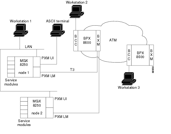
A representation of the feeder application of the MGX 8250 shelf appears in Figure5-1.
A representation of the stand-alone application of the shelf appears in Figure5-2.
Figure 5-1 Feeder Application
Figure 5-2 Stand-Alone Application
At the CLI prompt on the ASCII terminal perform the following steps.
Step 1
The terminal displays the slot number of the PXM1 you have logged into by default:
card number [7].
Step 2
At runtime, you could also enter the slot number of a service module or a standby PXM1. In this case, the CLI prompt shows:
NODENAME.1.7.PXM.a>
where NODENAME shows that the node has no name; the slot number of the PXM1 is 7; and this PXM1 is active. The general format of the CLI prompt is:
nodename.1.slot.cardtype.a>
where nodename is the name of the node; the shelf (node) number is always 1; slot is the card location; cardtype identifies the card; and the card state is active (a) or standby (s).
Step 3
NODENAME.1.7.PXM.a> dspcds
Step 4
NODENAME.1.7.PXM.a> dspifip
Step 5
NODENAME.1.7.PXM.a> cnfifip <interface> <IP_Addr> <Net_Mask> [BrocastAddr]
where interface is a number: 26 is the Ethernet (LAN AUI) port, 28 is the maintenance port (SLIP), or 37 for the ATM IP address (feeder application only). Note that BrocastAddr applies to only the Ethernet interface (number 26).
Note
Step 6
UNKNOWN.1.7.PXM.a> cnfname <node name>
where node name is a case-sensitive name up to eight characters. For example,
UNKNOWN.1.7.PXM.a> cnfname cisco22
Step 7
cisco22.1.7.PXM.a> cnftime <hh:mm:ss>
hh
The hour of the day in the range 1-24
mm
The minute of the hour in the range 1-60
ss
The number of seconds in the minute and has a range of 1-6
Step 8
•
•
Step 9
Before it sends statistics, the MGX 8250 node must have the IP address of the workstation with this application. The syntax is
>cnfstatsmgr <IP_Addr>
If the node has a redundant PXM1, it automatically receives the same IP addresses and configuration as the primary PXM1. With the IP addresses in place, you can configure the logical ports for the broadband interface through the CiscoView application or the CLI.
Step 10
Note
adduser <user_Id> <accessLevel>
After you enter a user-name and privilege level, the system prompts for a password. The password is a string of 5-15 characters. If you press Enter without entering a password, the system assigns the default password "newuser."
Step 11
cnfpasswd [username]
username is the name of another user whose password you are changing. That user must have a privilege level that is lower than your privilege. To change your own password, enter cnfpasswd with no username.
Step 12
cnfswfunc <-ndtype>
and follow -ndtype with "fdr."
Step 13
a.
cnfextclk <clock-type>: "1" is for T1 connections, "2" is for E1 connections.b.
cnfclklevel 4: to enable Stratum-4 clocking.
cnfclklevel 3: to enable Stratum-3 clocking.
Note
Note
Note
Step 14
cnfcbclk <cellBus> <clockRate>
cellBus
A string in the range CB1-CB8 that identifies the cell bus
clockRate
A number that identifies the rate in megahertz; choices are 21 or 42
The distribution of the eight cell buses follows.
•
•
•
•
•
•
•
•
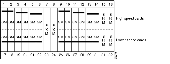
In the top bay, each of the six cell buses serves two card slots. In the bottom bay, each of the two cell buses serves six card slots. Therefore, each top slot has three times the available bandwidth of the lower slots and is therefore better suited to the higher speed cards. The bandwidth concentration for cell buses in the upper and lower bays is illustrated in Figure5-3.
Figure 5-3 Bandwidth Concentration in Upper and Lower Bays
Downloading Firmware to a Service Module
This section contains instructions to load service module firmware from a workstation to the hard drive on the PXM1. This is done when upgrading the existing firmware or because no runtime firmware resides on the hard drive.
Service modules do not retain runtime firmware. The hard drive on the PXM1 may come with default firmware for the service modules, but the details of the customer order actually determine whether firmware is on the disk. If default firmware exists on the hard drive, the PXM1 downloads it upon power-up or when you reset the card. You can download firmware from the workstation according to the instructions that follow.
Note
Step 1
$tftp <IP address>
then
>bin
Step 2
>put cardtype.fw POPEYE@SM_1_0.FW
cardtype is the firmware for a type of card; the shelf number always is 1; and the 0 represents the slot number for the purpose of generic download. An example of cardtype.fw is "frsm8t1e1_10.0.11.fw." Note the space between ".fw" and "POPEYE."
Step 3
>put cardtype.fw POPEYE@SM_1_slot.FW
cardtype is the firmware, and slot is the number of the card slot. Note the space between ".fw" and "POPEYE." Repeat this step for each slot as needed.
Note
With slot-specific firmware, the card does not come up if you:
•
•
An example command for downloading specific firmware for an FRSM-2CT3 in slot 3 is
>put frsm2ct3_10.0.01.fw POPEYE@SM_1_3.FW
"frsm2ct3_10.0.0" refers to the firmware for the FRSM-2CT3, and "3" is the slot.
Note
Step 4
Step 5
cisco22.1.7.PXM.a> ll c:/FW
Step 6
![]()
![]()
![]()
![]()
![]()
![]()
![]()
![]()
Posted: Thu Mar 4 20:52:45 PST 2004
All contents are Copyright © 1992--2004 Cisco Systems, Inc. All rights reserved.
Important Notices and Privacy Statement.