|
|

Table Of Contents
3
Installation Summary
Introduction
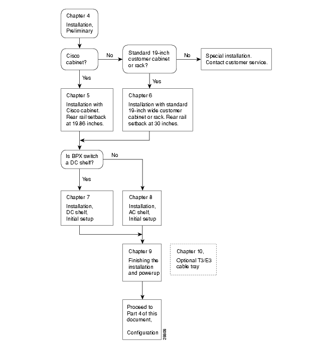
This part of the manual provides installation and power-up instructions for the BPX 8600 Series wide-area switches. This chapter provides a summary of the procedures and a flow diagram showing the overall installation tasks covered in PART 3 of this manual.
•
Installation instructions are provided in this part, PART 3.
•
•
•
•
For additional information on the BPX switch, including card descriptions and additional information on configuration, refer to the Cisco BPX 8600 Series Reference. For a description of the commands used to operate a BPX switch, refer to the Cisco WAN Switching Command Reference. Refer to the Cisco WAN Manager manuals for information on network management.
Installation Sequence
shows the sequence of operations followed during the installation of the BPX switch. A summary of this sequence is as follows:
•
•
•
•
The BPX switch shelves are either AC or DC powered. At the completion of the procedures in Chapter 5 or Chapter 6, the installer is directed to the appropriate power setup and connection chapter:
•
•
The remaining installation procedures are common and the installer is directed to the final setup and configuration procedures in:
•
An optional cable management tray and optional BXM T3/E3 cable management brackets are available for use with T3/E3 BXM cards. The brackets are for use with cards set up as non-redundant (single cables rather than Y-cabling). The tray is designed primarily for use in a mid-mount open rack configuration. Instructions for installing the optional tray are provided in:
•
Following the completion of these installation procedures, the BPX switch can be configured. Configuration procedures are provided in PART 4, Configuration, General.
Figure 3-1 Installation Sequence
Support
Contact your local Cisco sales office for Customer Service information.
![]()
![]()
![]()
![]()
![]()
![]()
![]()
![]()
Posted: Tue May 10 21:34:15 PDT 2005
All contents are Copyright © 1992--2005 Cisco Systems, Inc. All rights reserved.
Important Notices and Privacy Statement.