|
|

This chapter provides installation steps for the mechanical placement of a BPX switch shelf in a standard Cisco cabinet. This cabinet provides rear rails at a 19.86 inch (50.5 cm) setback from the front of the cabinet. This chapter also provides instructions for installing a 7200 or 7500 router in a BPX 8650 cabinet or rack.
Before proceeding to this chapter, the procedures should be completed, in:
The chapter contains the following:
The steps in this procedure apply to a BPX switch shelf that is being installed in a Cisco cabinet and using factory installed rear rails located at 19.86 inches from the front mounting flanges.
If the BPX switch shelf is DC-powered, the DC Power Entry Modules are factory-installed in the lower portion of the rear of the BPX switch shelf (see Figure 5-1). Locate the DC Power Entry Module(s) and make sure it/they are equipped as ordered. If the BPX switch shelf is AC-powered, an AC Power Tray is installed below it as part of the installation process.
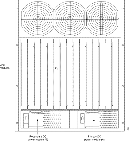
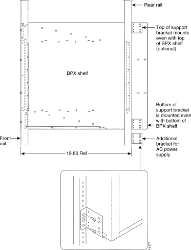
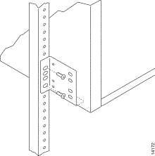
Proceed as follows to install either an AC or DC powered BPX switch shelf, referring to Figure 5-2 and Figure 5-3 and to either Figure 5-4 for DC powered systems or Figure 5-5 for AC powered systems:
Step 2 Slide the BPX switch shelf into the cabinet over the temporary support bar and brackets and into place over the flanges of the brackets previously attached to the rear rails of the cabinet.
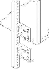
Step 3 Locate the rear support brackets (P/N 215960-00B and 215960-01B) in the miscellaneous parts kit.
Step 4 Secure one support bracket to the back of each of the two rear rails located at 19.86 inches from the front flange of the Cisco cabinet using two each #10-32 machine screws and flat washers per bracket. The flange on each bracket faces down and inward to support the bottom of the BPX shelf.
 | Warning An empty BPX switch shelf weighs 75 pounds (34 Kgs.) and requires a 2 or 3-person lift to move into place. |
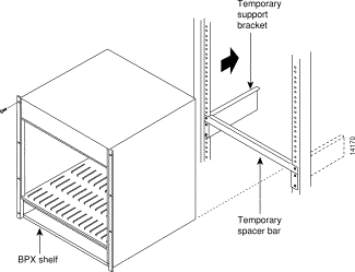
Step 5 Attach the BPX switch shelf to the cabinet front rail using 8 each # 10-32 screws.
Step 6 An extra set of support brackets may optionally be mounted to the rear rails at the top back of the shelf. These are used to prevent any upward movement of the shelf.
Step 7 Remove the temporary support brackets and spacer bar.
Step 8 If this is a DC powered shelf, proceed to Chapter 7, Installation, DC Shelf Initial Setup.
Step 9 If this is an AC powered shelf, proceed to Chapter 8, Installation, AC Shelf Initial Setup.
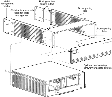
The steps in this procedure apply to a 7200 or 7500 Router Label Switch Controller assembly that is being installed in a Cisco cabinet as part of a BPX 8650 installation. A hardware kit is provided with the router and router enclosure that contains support brackets and other required hardware.
(a) Place router into router enclosure as shown (see Figure 5-6) with power connector side of router towards hinged front door of router enclosure.
(b) Install power cord along top left side of router and router enclosure.
(c) Mount front hinged door to router enclosure by spreading sides of router enclosure slightly so that holes in each side of the cover engage the pins at the front of the router enclosure.
(d) Secure router to router enclosure using four screws on each side.
(e) You can attach cable management brackets now or later, as desired. The upper end of each bracket hooks into the square cutouts shown in Figure 5-6 and the bottom of each bracket is secured with screws.
Step 2 To install the router assembly in a BPX 8650 cabinet, a 19-inch open rack, or a 23-inch open rack, choose the applicable one of the following:
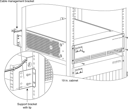
Install router enclosure assembly in BPX 8650 cabinet as follows (see Figure 5-7):
Step 2 Attach the two support brackets from the hardware kit, one to each vertical rail at the back of the cabinet as shown using two screws to secure each. The support brackets have a horizontal flange which supports the router enclosure assembly.
Step 3 Secure front of router assembly to cabinet rails with two screws on each side.
Step 4 Secure router enclosure assembly to cabinet with mounting screws.
Step 5 Connect power cord to router connector receptacle at front of cabinet, and close the router enclosure assembly door.
Step 6 Use the tie wraps provided in the hardware kit to secure power cord to a Cable Management Bracket.
Step 7 If this is a DC powered shelf, proceed to Chapter 7, Installation, DC Shelf Initial Setup.
Step 8 If this is an AC powered shelf, proceed to Chapter 8, Installation, AC Shelf Initial Setup.
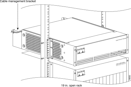
Install router enclosure assembly in BPX 8650 cabinet as follows (see Figure 5-8):
Step 2 Attach the two support brackets (for 19-inch open rack mounting) from the hardware kit, one to each side of the router enclosure assembly, using two securing screws for each bracket.
Step 3 Secure front of router assembly to rack with two screws on each side.
Step 4 Connect power cord to router connector receptacle at front of cabinet, and close the router enclosure assembly door.
Step 5 Use the tie wraps provided in the hardware kit to secure power cord to a Cable Management Bracket.
Step 6 If this is a DC powered shelf, proceed to Chapter 7, Installation, DC Shelf Initial Setup.
Step 7 If this is an AC powered shelf, proceed to Chapter 8, Installation, AC Shelf Initial Setup.
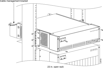
Install router enclosure assembly in BPX 8650 cabinet as follows (see Figure 5-9):
Step 2 Attach the two support brackets (for 23-inch open rack mounting) from the hardware kit, one to each side of the router enclosure assembly, using five securing screws for each bracket.
Step 3 Slide router enclosure assembly into cabinet on top of BPX shelf.
Step 4 Secure front of router assembly to rack with three screws on each side.
Step 5 Connect power cord to router connector receptacle at front of cabinet, and close the router enclosure assembly door.
Step 6 Use the tie wraps provided in the hardware kit to secure power cord to a Cable Management Bracket.
Step 7 If this is a DC powered shelf, proceed to Chapter 7, Installation, DC Shelf Initial Setup.
Step 8 If this is an AC powered shelf, proceed to Chapter 8, Installation, AC Shelf Initial Setup.
![]()
![]()
![]()
![]()
![]()
![]()
![]()
![]()
Posted: Thu Jul 26 18:10:44 PDT 2001
All contents are Copyright © 1992--2001 Cisco Systems, Inc. All rights reserved.
Important Notices and Privacy Statement.