|
|

This chapter explains how to install the BPX switch cards, check for a 9.6 or 19.2 Gbps backplane, connect line and trunk cables, connect peripherals, connect to a network management station, initial power up, and initial configuration.
Before proceeding to this chapter, the procedures should be completed, in either:
This chapter contains the following sections:
 | Caution Ground yourself before handling BPX switch cards by placing a wrist strap on your wrist and clipping the strap lead to the cabinet, or use the wrist strap that is connected to the cabinet. |
The card shelf in the BPX switch has card slots numbered from 1 to 15, as viewed from left to right from the front of the cabinet. Front and rear views of the BPX switch card shelf are shown in Figure 9-1 and Figure 9-2, respectively. The configuration rules for the BPX switch are summarized as follows.
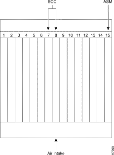
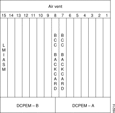
 | Caution Ground yourself before handling BPX switch cards by placing a wrist strap on your wrist and clipping the strap lead to the cabinet, or use the wrist strap that is connected to the cabinet. |
 | Caution Blank Front Card and Rear Face Plates must be used to fill/cover empty card slots to eliminate Radio Frequency Interference (RFI) and Electromagnetic Interference (EMI) and to ensure correct air flow through the card cage. |
Systems may be shipped with empty shelves, with filler cards or with plug-in cards installed. If filler cards are installed in each slot, some of them may need to be replaced with functional cards. The front cards are held captive mechanically by the Air Intake Grille and can not be removed until the lower Air Intake Grille is released.
 | Caution Do not attempt to remove a front card from the BPX switch cabinet until the Air Intake Grille is released and lowered or the Air Intake Grille and/or card extractors may be damaged. |
Proceed as follows to remove/install a front card.
 | Caution Before any card is installed, always examine the chassis backplane and card cage guides for any signs of loose or misplaced EMI gasketing. Examine the backplane connectors for bent or damaged connection or pre-power pins. |
Step 2 Locate the small access hole in the top center of the front Air Intake Grille below the card slots (see Figure 9-3 for location).
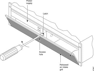
Step 3 Insert a small slotted blade screwdriver (0.20/0.25 inch blade width) into the access hole until it stops (approximately 1 inch).
Step 4 Carefully rotate the screwdriver approximately a quarter turn in either direction. The top of the Air Intake Grille should spring out.
Step 5 Remove Air Intake Grille.
Step 6 To remove a card, rotate the extractor handles at the top and bottom of the card to release the card and slide it out.
Step 7 To insert a new card, position the rear card guides over the appropriate slots at the top and bottom of the card cage.
Step 8 Gently slide the card in all the way to the rear of the slot and seat the board by fully seating both extractor handles. The handles should snap back to a vertical position when seated.
 | Caution Ground yourself before handling BPX switch cards by placing a wrist strap on your wrist and clipping the strap lead to the cabinet, or use the wrist strap that is connected to the cabinet. |
The optical ports contain an information label as shown in Figure 9-4.

 | Warning Invisible radiation may be emitted from the optical ports of the single-mode or multi-mode products when no fiber cable is connected. Avoid exposure and do not look into open apertures. (For translated versions of this warning, refer to the Regulatory Compliance and Safety Information that accompanied your equipment). |
 | Warning Class 1 laser product. (For translated versions of this warning, refer to the Regulatory Compliance and Safety Information that accompanied your equipment). |
 | Warning Laser radiation when open. (For translated versions of this warning, refer to the Regulatory Compliance and Safety Information that accompanied your equipment). |
Proceed as follows to install back cards:
Step 2 For existing installations, remove any cable(s) that may be attached and tag them so they may be replaced in the same location.
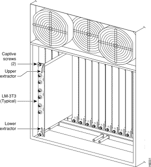
Step 3 Loosen the captive mounting screws on both top and bottom of the line module faceplate with a slotted blade screwdriver (see Figure 9-5).
Step 4 Lift the extractor handles at the top and bottom, and slide out the line module.
Step 5 To re-insert the line module, locate the corner edges of the card into the appropriate guide slots at the top and bottom of the card cage. Gently slide the card in all the way to the rear of the slot and push to seat the card in the connector.
Step 6 Screw in the captive screws.
Step 7 Replace any cables that may have been removed in step 2.
In order to operate the BPX Switch at 19.2 Gbps the following is required:
The 19.2 backplane can be visually identified by the small white card slot fuses at the bottom rear of the backplane. These fuses are approximately 1/4 inch high and 1/8 inch wide. The 9.6 Gbps backplane does not have these fuses. If the BPX Switch is a late model, then a 19.2 Gbps backplane is installed. This can be verified by running the dspbpnv command which will display "Word #2 =0001" if the backplane NOVRAM has been programmed. If anything else is displayed, you'll have to visually check the backplane for the fuses.
If the backplane is a 19.2 Gbps backplane, but the backplane NOVRAM has not been set to display Word #2 =0001, then the cnfbpnv command may be used to program the NOVRAM as follows:
Are you sure this is a new backplane (y/n).
Step 2 Enter y
Step 3 Confirm that the change has been made by entering dspbpnv to confirm the response:
Word #2 =0001
Step 4 Enter switchcc in order for the change to be recognized by the switch software.
If the backplane is not a 19.2 Gbps backplane, then it will be necessary to install a 19.2 Gbps backplane to obtain 19.2 Gbps operation. Contact Customer Service.
The backplane must be a 19.2 Gbps backplane. Refer to the previous section, Verifying 9.6 or 19.2 Gbps Backplane. To upgrade to BCC-4 cards which support the 19.2 Gbps performance of the BXM cards, proceed as follows:
Step 2 Replace with new BCC-4 front and back cards.
Step 3 Wait for the standby updates on the newly installed standby BCC-4 to complete.
Step 4 Issue a switchcc command to utilize the newly installed BCC-4.
Step 5 Verify that the network is stable.
Step 6 Remove the current standby BCC front and back card.
Step 7 Replace with new BCC-4 front and back cards that are identical to the current active BCC-4.
Step 8 Wait for the standby updates on the newly installed standby BCC-4 to complete.
Step 9 The BCC-4 physical upgrade is now complete.
After step 2, the node will contain a mix of an old type BCC and the new type BCC-4. This condition is only permitted while the standby updates to the new BCC are in progress, which will take less than one hour.
The time during which this mixture of BCC types exists must be kept to a minimum, by immediately replacing the second old type BCC with the matching one of the new type.
The following procedures provide installation instructions for the SONET Automatic Protection System (APS) Redundant Frame Assemblies and backcards which may be used to provide line and card redundancy for BXM OC-3 and OC-12 cards.
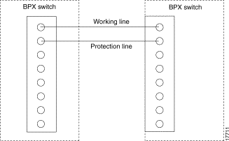
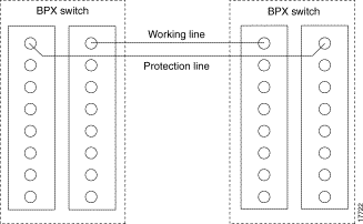
The following APS protocols that are supported by the BXM are listed in Table 9-1 and shown in Figure 9-6 and Figure 9-7.
| The APS 1:1 redundancy provides line redundancy, using adjacent lines on the same BXM backcard. |
| The APS 1+1 redundancy provides card and line redundancy, using the same numbered ports on adjacent BXM backcards. |
APS 1:1 redundancy provides line redundancy only and is supported with the standard BXM OC-3 and OC-12 front and back cards.
APS 1+1 redundancy, which provides both card and line redundancy uses the standard BXM OC-3 and OC-12 front cards, but requires a special APS Redundant Backplane and APS Redundant backcards.
With previous card cages, because of the positioning of mechanical dividers, the APS card pairs can only be inserted in certain slots. These are slots 2 through 5 and 10 through 13. The mechanical dividers are located at slots 1 and 2, 5 and 6, 9 and 10, and 13 and 14.
With current card cages, this limitation is removed, and the APS card pairs can be located anywhere, except BCC cards slots 7 and 8, and ASM card slot 15. An APS 1+1 redundant card pair must be in adjacent slots (2,3 or 4,5 etc.).
Proceed to install APS Redundant Frame Assembly and backcards as follows:
 | Warning Nylon standoffs on the APS Redundant Frame Assembly must be in place to prevent shorting against -48 VDC pins and ground pins on the BPX Midplane. |
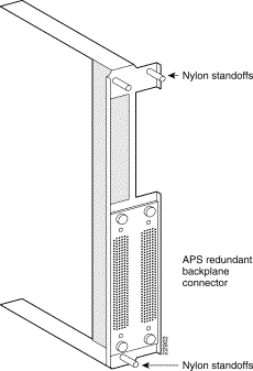
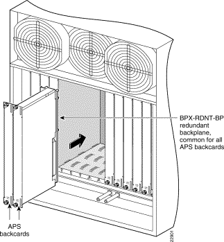
Step 2 Verify that nylon standoffs are securely installed on APS Redundant Frame Assembly (see Figure 9-8).
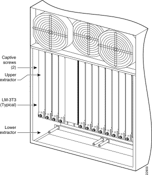
Step 3 Carefully slide APS Redundancy Frame Assembly and APS cards into selected side-by-side slots at the back of the BPX shelf (dee Figure 9-9). Slide the APS Redundancy Frame Assembly and cards into the BPX shelf until snug against the BPX midplane (see Figure 9-10).
Step 4 Going back and forth between the screws, gradually tighten retaining screws at top and bottom of the APS backcards until they are secure.
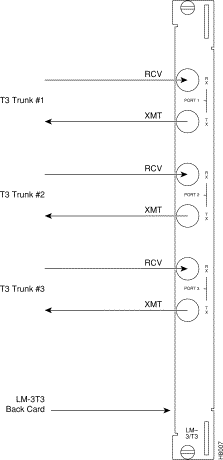
Each LM-3T3 and LM-3E3 line module (BNI backcard) provides three ports with a BNC connector each for the XMT trunk output and for the RCV trunk input. Each LM-2T3 and LM-2E3 line module (ASI backcard) provides two ports with a BNC connector each for the XMT line output and for the RCV line input. Make the T3/E3 connections to each port as follows.
Step 2 The BPX switch has tie-downs inside the cabinet to hold cabling in place. Pull them apart as applicable, place the routed cable in position, wrap the ties around the cable and remake the loops by pressing the two sections together.
Step 3 Connect the cables to the BNC connectors on the LM-3T3 or LM-3E3 line modules. Remember, the RCV is an input to the BPX switch and XMT is an output from the BPX switch. The ports are numbered from top to bottom as indicated in Figure 9-11.
Step 4 Record which slot and port number are used for each trunk or line. You'll need the information later when configuring the network.
Step 5 If optional Y-cable redundancy is desired, locate a 3-way BNC Y-cable adapter for each port to be so equipped. As an alternative to the Y-cable, use a BNC "T" and two short BNC-BNC cables.
Step 6 For card redundancy, make sure there are two appropriate line modules equipped in adjacent slots.
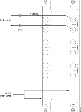
Step 7 Connect two legs of the Y-cable to the XMT T3 or E3 connectors on the same port on each of the two line modules (see Figure 9-12). Do the same with the two RCV T3 or E3 connectors.
Step 8 Connect the third leg of the XMT and RCV Y-cable adapters to the XMT and RCV trunk cable.
Step 2 The Cisco cabinet has tie-downs inside the cabinet to hold cabling in place. If using a Cisco cabinet, pull the tie downs apart as applicable, place the routed cable in position, wrap the ties around the cable and remake the loops by pressing the two sections together.
Step 3 Connect the cables to the applicable connectors on the OC-3 line modules. Remember, the RCV is an input to the BPX switch and XMT is an output from the BPX switch. The ports are numbered from top to bottom as indicated in Figure 9-13.
Each OC-3 or OC-12 line module provides ports with both a transmit and receiver connector for each port. The following applies to OC-3 and OC-12 backcards, except that Y-Cabling redundancy is supported only for the SMF cards. Make connections as follows:
Step 2 The Cisco cabinet has tie-downs inside the cabinet to hold cabling in place. If using a Cisco cabinet, pull the tie downs apart as applicable, place the routed cable in position, wrap the ties around the cable and remake the loops by pressing the two sections together.
Step 3 Connect the cables to the applicable connectors on the line modules. Remember, the RCV is an input to the BPX switch and XMT is an output from the BPX switch. The ports are numbered from top to bottom.
Step 4 Record which slot and port number are used for each trunk or line. You'll need the information later when configuring the network.
Step 5 A Y-Cable redundancy connection for the SMF-2-BC backcard is shown in Figure 9-13. Y-Cable redundancy is supported only for the SMF-2-BC backcard which is used with either the BNI-155 or the ASI-155.
Step 6 For card redundancy, make sure there are two appropriate line modules equipped in adjacent slots.
Step 7 Connect two legs of the Y-cable to the XMT connectors on the same port on each of the two line modules (see Figure 9-13). Do the same with the two RCV connectors.
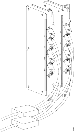
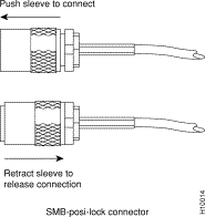
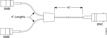
Each T3/E3 line module provides ports with both a transmit and receiver connector for each port. The backcards can provide 4, 8, or 12 ports. Figure 9-14 shows a typical T3/E3 cable connector that connects to the BXM T3/E3 cards. Y-Cabling redundancy is supported on the BXM T3/E3 cards. An example of a Y-cable is shown in Figure 9-15.
Make connections as follows:
Step 2 The Cisco cabinet has tie-downs inside the cabinet to hold cabling in place. If using a Cisco cabinet, pull the tie downs apart as applicable, place the routed cable in position, wrap the ties around the cable and remake the loops by pressing the two sections together.
Step 3 Connect the cables to the applicable connectors on the T3/E3 line modules. Remember, the RCV is an input to the BPX switch and XMT is an output from the BPX switch. The ports are numbered from top to bottom.
Step 4 For an open rack configuration and where Y-redundancy is not being used, an optional cable management tray is available to help route cables when a number of DS3/T3 cards are installed resulting a large number of cables to handle. Refer to Chapter 10, T3/E3 Cable Management Tray.
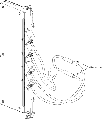
The two ports on the OC-12 backcard for the BME multicast card are setup of by connecting the transmit of port 1 to the receive of port 2 and the receive to port 1 to the transmit of port 2, thus looping the two ports together. This is shown in Figure 9-16.
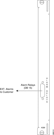
Dry contact relay closures are available for forwarding BPX switch alarms to a user office alarm system. Separate visual and audible alarm outputs are available for both major as well as minor alarm outputs. These outputs are available from a DB15 connector on the LM-ASM faceplate (see Figure 9-17). Refer to Appendix B, BPX Switch Cabling Summary, for a list of the pinouts for this connector. Use switchboard cable for running these connections.
The BPX switch has two RS-232 serial data ports (labeled CONTROL port and AUXILIARY port) and an Ethernet port (labeled LAN) on the LM-BCC back card for attaching peripherals.
A network (or each domain in a structured network) must have at least one connection to a control terminal or Cisco WAN Manager network management workstation. The Cisco WAN Manager NMS workstation is used to configure and maintain all nodes in a network and report network statistical data. In addition, a network printer must be connected to the AUXILIARY port if you wish to print.
If it is desired to have Customer Service perform remote troubleshooting, a dial-in modem must be attached to the network. Procedures for attaching peripherals to the BPX switch are contained in the following paragraphs. Be sure to read the manufacturers literature to ensure that you have made the equipment ready for attachment, before attempting to attach it to the BPX switch.
Refer to the following for additional information on the following related subjects:
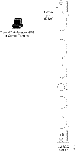
A basic VT-100 type terminal may be connected to this port for use in entering commands to bring up a new node. (Note: Since the Cisco WAN Manager NMS workstation requires a LAN connection to a node in the network in order to perform its management functions, it is not connected to the Control Port during normal operation.) In these procedures, the term BCC is used to refer to the BCC-4V, BCC-3-32M, BCC-3-64M, or BCC-32. The BCC-4V, BCC-3-32M, and BCC-3-64M require BCC-3-BC backcards, and the BCC-32 requires the BCC15-BC backcard.
Attach a terminal to the BPX switch as follows:
Step 2 For nodes with a single BCC: Locate the CONTROL port connector on the LM-BCC in slot 7. Attach the RS-232/V.24 cable as shown in Figure 9-18, the proceed to Step 5.
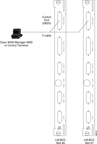
Step 3 For nodes with redundant BCCs: A single cable is sufficient for temporarily connecting to the CONTROL port of the active BCC during initial node configuration. However, if for some reason you want to monitor the switchover function of the BCCs via the CONTROL port without swapping the cable from the CONTROL port of one BCC to the CONTROL port of the other, you can use a Y-cable. Connect one leg of the Y-cable to the CONTROL port connector on the backcard in slot 7 and the other leg to the slot 8 CONTROL port connector.
Step 4 Attach a RS-232/V.24 cable to the remaining leg of the Y-cable as shown in
Figure 9-19.
Step 5 Fasten the cable connector to the CONTROL port connector with the captive screws on the connector hood.
Step 6 Plug the control terminal (or Cisco WAN Manager) power cord into the appropriate wall receptacle (115 VAC or 240 VAC) and switch it on.
Step 7 Set the port function for VT100/StrataView using the cnftermfunc command if connecting to a Cisco WAN Manager workstation. If using a "dumb" terminal, select VT100 only (# 5).
Step 8 Make sure that the CONTROL port and the terminal or workstation are set to the same baud rate and check the other communication parameters using the cnfterm command.
Step 9 When you have completed the initial node configuration, you remove the connections to the CONTROL Port(s). Network Management connections are described in the next section.
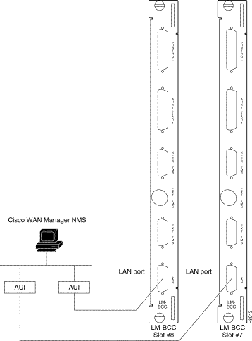
The Cisco WAN Manager NMS is connected to an Ethernet port (LAN port) on a node in the network for the purpose of network management. The LAN port provides the capacity necessary for the network management traffic and network statistics collection. See Figure 9-20 illustrating this connection.
For access to the node using an Internet connection, the Internet Protocol (IP) address, IP subnet mask, TCP service port, and gateway IP address must be entered by the user with the cnflan command.
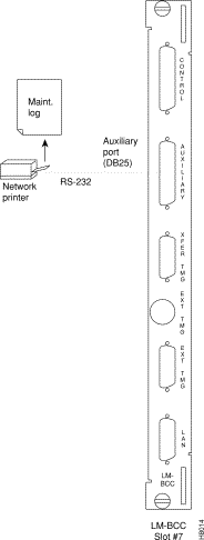
In most systems, the network printer will be connected to a serial port on the Cisco WAN Manager NMS terminal server. The maintenance log and all statistics data will reside on the Cisco WAN Manager. However, it is possible to connect a printer to a node and use various BPX switch software print commands to print locally. This may be helpful during the initial network installation phase.
Appendix C, BPX Switch Peripherals, lists the types of printers supported by the BPX switch along with configuration settings. Appendix B, BPX Switch Cabling Summary lists the pin assignments for the AUXILIARY port on the BPX switch and the recommended RS-232/V.24 cable pinout and printer DIP switch settings. Attach the printer to the BPX switch as follows:
Step 2 For nodes with single BCC: Connect the RS-232/V.24 printer cable to the AUXILIARY port on the LM-BCC back card (see Figure 9-21). Go to Step 4.
Step 3 For nodes with redundant BCCs: A Y-cable is required for this application. Connect one leg of the Y-cable to the AUXILIARY port connector on the LM-BCC in slot 7 and the other leg to the AUXILIARY port connector on the LM-BCC in slot 8.
Step 4 Plug the printer power cord into the appropriate AC outlet (115 VAC or 240 VAC).
Step 5 Set the port function for printer using the cnftermfunc command.
Step 6 Make sure the control port and the printer are set to the same baud rate and check the other communication parameters using the cnfterm command.
A modem may be connected to each BPX switch to provide remote access by Customer Service (see Figure 9-22). For information on connecting and configuring a modem refer to Appendix C, BPX Switch Peripherals.
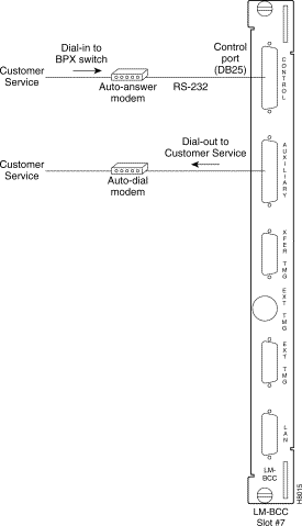
These modems connect to a standard telephone line wall jack. The modem connections require special cables and setup procedures. Refer to Appendix C, BPX Switch Peripherals, for instructions on connecting and setting up the modems. If the BPX switch is equipped with redundant BCCs, an RS-232 Y-cable must be used for these connections.
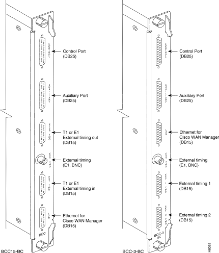
If the BPX switch is to be synchronized to some other external equipment or a local digital central office, one of two connectors on an BCC15-BC backcard (backcard for BCC-32) can be used to accept a clock input. A DB15 connector labeled EXT TMG can be used to connect a balanced T1 or E1 signal, synchronized from some higher-level source, to the BPX switch. If an unbalanced 75-ohm E1 signal is available as the timing source, a BNC EXT TMG connector is also provided.
For a BCC-3-BC backcard (backcard for BCC-3-32M, BCC-3-64M, or BCC-4V), A DB15 connector labeled EXT 1 TMG can be used to connect a balanced T1 or E1 signal, synchronized from some higher-level source, to the BPX switch. EXT 2 TMG connector provides a redundant connector to EXT 1 TMG. A T1 source with 100 ohm impedance or an E1 source with 100/120 ohm impedance typically uses this connector. If an unbalanced 75-ohm E1 signal is available as the timing source, a BNC EXT TMG connector is also provided.
The BPX switch can use these inputs rather than its internal Stratum 3 clock source.
Before operating the BPX switch, check that the following procedures have been performed:
Step 2 The BPX switch power cord is plugged into an appropriate power outlet.
Step 3 The full complement of cards for the specific node are mounted in the correct slots, correctly seated, and locked in place.
Step 4 The T3 or E3 connections are attached to the appropriate LM-3T3/3E3 faceplate.
Step 5 A control terminal (or Cisco WAN Manager Work Station) is connected to the CONTROL port on the LM-BCC in back slot 7/8, and the terminal's power cord plugged into the appropriate voltage wall outlet.
Step 6 If needed, a printer may be connected to the AUXILIARY port on the LM-BCC in back slot 7/8 and the printer power cord plugged into the appropriate power outlet.
Step 7 If needed, a modem(s) may be connected to the CONTROL port or AUXILIARY port, as applicable, on the LM-BCC in back slot 7/8, and the modem(s) power cord(s) plugged into the appropriate power wall outlet.
Step 8 From the back of the BPX switch, turn the power switches to the ON position.
Step 9 From the front of the BPX switch, observe the cards go through initial diagnostic self-tests.
The BPX switch software provides a group of diagnostic tests to be run on the system's hardware at power-up. The startup diagnostic either passes or fails the BCC(s) tests. The test result is displayed on the screen of a control terminal connected to the CONTROL port on the backcard in slot 7 of the BPX. A successful power up results in a pass message.
If a BCC fails the power-up diagnostic, it will not boot. When that happens, do the following:
Step 2 Reseat the BCC in the same slot.
Step 3 Wait for the power-up diagnostic to run.
Step 4 If the BCC fails the power-up diagnostics a second time, replace it with another BCC that is known to have passed the test.
Once the software has successfully booted up, a terminal connected to the CONTROL port or an NMS workstation connected via a telnet session to the LAN port will display the software on-line screen as shown in the following example. At this point, you may login as a user to the node.
Sample display:
pubsbpx1       TN    No User         BPX 15    9.2      Nov.  21 1998       14:15 PST


Enter User ID:
For provisioning of the BPX switch, including configuring ports, lines, trunks, and adding connections refer to the following documents:
Proceed to Chapter 11, Configuration, Introduction, for configuration procedures for the BPX switch.
![]()
![]()
![]()
![]()
![]()
![]()
![]()
![]()
Posted: Thu Jul 26 18:18:08 PDT 2001
All contents are Copyright © 1992--2001 Cisco Systems, Inc. All rights reserved.
Important Notices and Privacy Statement.