|
|

Table Of Contents
Installation with Customer Cabinet
Installing a BPX Switch, Rear Rail Setback at 30-Inch
6
Installation with Customer Cabinet
This chapter provides installation steps for the mechanical placement of a BPX switch shelf in a standard 19-inch customer supplied equipment cabinet or rack with a rear rail setback at 30 inches.
Before proceeding to this chapter, the procedures should be completed, in:
•
Chapter 4,
Installing a BPX Switch, Rear Rail Setback at 30-Inch
The steps in this procedure apply to a BPX switch shelf that is being installed in a customer supplied cabinet with rear vertical rails located at a setback of approximately 30 inches from the front.
If the BPX switch shelf is DC-powered, the DC Power Entry Modules are factory-installed in the lower portion of the rear of the BPX switch shelf itself. Locate the DC Power Entry Module(s) and make sure it/they are equipped as ordered. If the BPX switch shelf is AC-powered, an AC Power Assembly will be installed below it.
Preliminary Procedure:
Proceed as follows to install the BPX switch shelf, referring to through , and to either for DC powered systems or for AC powered systems. shows the location of the rear located third rails in a customer supplied cabinet and of the corresponding adjustable plates and support brackets on the BPX switch shelf.
Step 1
Step 2
Step 3
Note
Step 4
Step 5
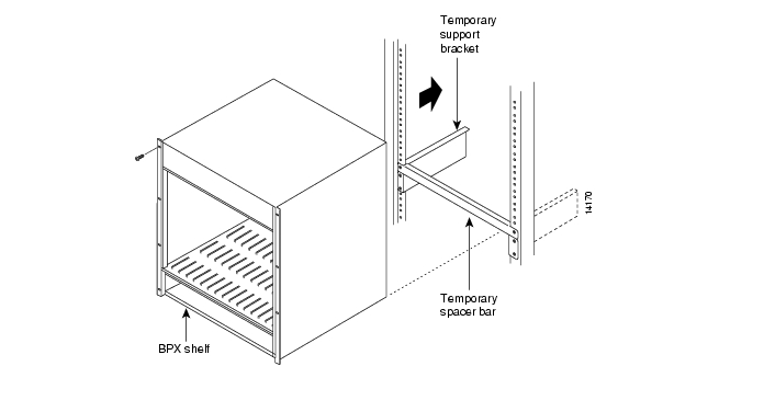
Figure 6-1 BPX Switch Aligned with Temporary Support Brackets and Spacer Bar
Step 6
Step 7
Step 8
Step 9
Step 10
Step 11
Step 12
Step 13
Step 14
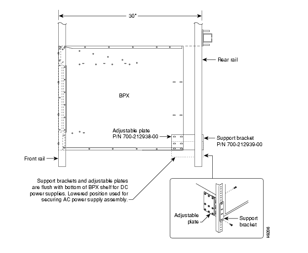
Figure 6-2 BPX Switch with Rear Rail Mounting at Setback of 30 Inches
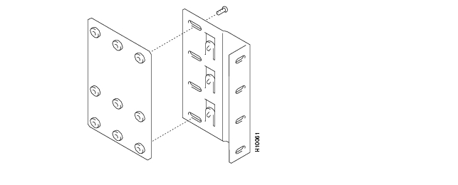
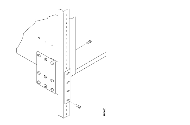
Figure 6-3 Rear Mounting Brackets, Detail
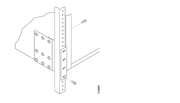
Figure 6-4 Rear Mounting Brackets, with 30 Inch Rear Rail Setback (DC Systems)
Figure 6-5 Rear Mounting Brackets, 30 Inch Rear Rail Setback (AC-Powered Systems)
![]()
![]()
![]()
![]()
![]()
![]()
![]()
![]()
Posted: Tue May 10 21:32:53 PDT 2005
All contents are Copyright © 1992--2005 Cisco Systems, Inc. All rights reserved.
Important Notices and Privacy Statement.