|
|

This chapter includes the following sections:
This chapter describes the FastPADmpr12 and FastPADmpr24 front panels, rear panels, and processor boards. These systems come only in a rack version. The mpr24 is the same as the mpr12 except that the mpr12 is a two-module system and the mpr24 is a three-module system.
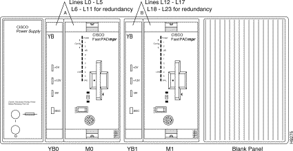
The FastPADmpr12 maintains network security by providing module (line) redundancy. A 1-1 line redundancy is achieved using a special backplane, two 12-line modules and two YB Boards (the circuit card equivalent of standard Y cables).
The FastPADmpr24 provides a 1-1 or a 1-2 line redundancy using a special port backplane, three 12-line modules and four YB boards.
In the event a module fails, the FastPADmpr12/24 automatically switches connections from the failed module to the other modules to maintain the correct number of lines up at all times.
The mpr runs the modules "hot," all sharing processing power and physical line responsibility. Modules 1 and 2 operate with only 6 active lines. Module 3 operates with 12 active lines.
The FastPADmpr is a shelf system using either of the following configurations:
Figure 4-1 shows the front panels of a fully configured FastPADmpr12 unit with two modules and two YB boards.
Figure 4-2 shows the front panels of a fully configured FastPADmpr24 unit with three modules and four YB-boards. The LEDs are described in Table 4-2.
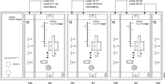
In Figure 4-2, YB boards are numbered for explanatory reasons. They do not have numbers. Table 4-1 summarizes which module governs which lines and which YB boards.
| Module | YB | User Lines |
|---|---|---|
M0 | YB0 | 0-5 |
M1 | YB1 | 11-17 |
M2 | YB2 YB3 | 24-29 30-35 |
The meaning and utilization of the mpr's front panel is exactly the same as for the mp and mp12. Refer to the chapter "FastPADmp Hardware Description" for details.
A YB board has no module number (it can occupy places YB0-YB3) and is "hot swappable." A YB board has four LEDs, which are described in Table 4-2.
YB boards have a dual power regulator system—that is, there is a redundant power supply in case one supply fails.
YB0 and YB1 back each other up while YB2 and YB3 back each other up.
The front panel of the YB board is illustrated in Figure 4-3.
| LED | State | Indication |
|---|---|---|
"SEC" | ON—red | Operation in backup mode (the associated module is out of order and the redundant module has taken over). Normal operation. |
-9 | ON—green ON—red OFF | Normal operation. -9 fuse blown, board out of order. Failure of the regulator of the corresponding power supply. |
+12 | ON—green ON—red OFF | Normal operation. +12/24 fuse blown, board out of order. Failure of the regulator of the corresponding power supply. |
+5V | ON—green ON—red OFF | Normal operation. +5 fuse blown and short circuit on the board; board out of order. Failure of the regulator of the corresponding power supply. |

The LED "Sec", which indicates that a module is down and being replaced by another or others, is described in Table 4-3.
| Sec is "on" (Red) | Module backed up |
|---|---|
YB0 | M0 |
YB1 | M1 |
YB2 & YB3 | M2 |
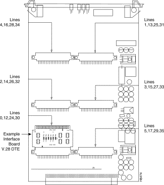
A YB card is fitted with the same interface card (V.28/V.11) that is used on the mp and mp12 devices. Each YB card can handle six lines, which are user lines. (See Figure 4-4.)
This section describes the FastPADmpr 12/24 rear panel, connectors, and power supply. The rear panel is illustrated in Figure 4-5.
The FastPADmpr12/24 uses DB-25 female connectors for 24 lines (L0-L35) and transputer links. In addition, there is an optional external ground connector. It is worth noting that the numbering scheme and placement of interfaces on the back of the box does not follow logical numerical order. Interfaces are instead grouped together around the processor that drives them.
Furthermore, gaps in the numbering scheme arise from the fact that although each module supports 12 lines, the first two modules only ever use six lines at a time and therefore only ever need six physical interfaces each. As shown above, the mpr 12/24 backplane has only 24 output lines. This backplane is specially designed to interface with the redundant YB cards.
All FastPADmpr12/24 units are rack-mounted and receive power from a power supply built into the rack.
See the appendix "Specifications" for specifications.
The purpose of the mpr system is to provide line backup in case of a module failure.
An mpr module has the potential to handle 12 ports, but on module 0 and module 1, only six ports are physically accessible. This means that both Module 0 and Module 1 each have six other lines that are always in stand-by, ready to provide backup.
Figure 4-6 illustrates the principle for an mpr24. In the case of an mpr12, module 2 is simply not present.
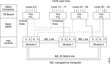
The backup function is automatic. The mpr module takes the initiative to carry it out. An Alarm Event can be automatically generated towards the NMS system. After repair of the downed module, it is up to the Network Manager to make the decision when to return to normal line use. Since it is undesirable and unnecessary to disrupt service to users who are operating normally, this task can be done during the night or low traffic periods.
A FastPADmpr12 provides 12 ports:
A FastPADmpr24 provides 24 ports:
For the user, there are 12 lines available (see Figure 4-7).
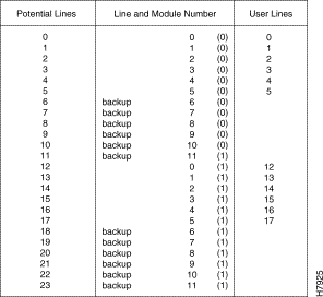
When a module has a hardware failure, the six user lines of the module to be "backed up" are interrupted for a moment and then replaced by the lines of the "backup" module. The user still has 12 lines available. Example: Module 1 has a failure. (See Figure 4-8.)
The user has 24 lines available (see Figure 4-9).
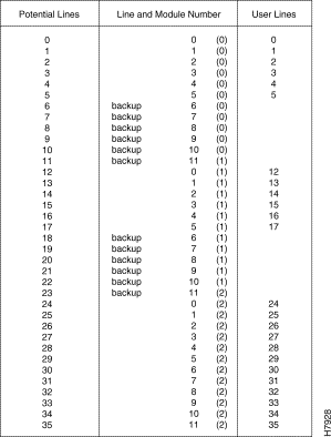
When a module has a hardware failure, the 6 or 12 lines of the module to be "backed up" are interrupted for a moment and then replaced by the 6 or 12 lines of the "backup" module(s). Example: Module 2 has a failure (see Figure 4-10).
The mpr is a shelf system that can be configured with two modules (mpr12) or three modules (mpr24).
mpr12:
mpr24:
Step 2 Attach the terminator on the rear panel.
Step 3 Set the interface on the YB card.
Step 4 Insert the SmartCard in the modules.
Step 5 Insert the first YB card.
Step 6 Insert the first mpr module.
Step 7 Insert the second YB board.
Step 8 Insert the second mpr module.
In you have an mpr 24, proceed to Step 9, Step 10, and Step 11. Otherwise, proceed to Step 12.
Step 9 Insert the third YB board.
Step 10 Insert the third mpr module.
Step 11 Insert the fourth YB board.
Step 12 Switch on power.
Step 13 Wait for the Autotest.
As with the mp12, the mprxx module can determine its own position in the shelf when it comes from the manufacturer. If the module does not arrive directly from the manufacturer, you have to force the module number using the front panel. Refer to the chapter "FastPADmp Hardware Description" for details.
![]()
![]()
![]()
![]()
![]()
![]()
![]()
![]()
Posted: Thu Jan 25 13:36:38 PST 2001
All contents are Copyright © 1992--2001 Cisco Systems, Inc. All rights reserved.
Important Notices and Privacy Statement.